Search results
Query: output
Links: 278 | Categories: 3
-
 The program consists of tabbed pages for various antenna and transmission line calculation. You can compute the values for an inverted L network that will allow you to match the 50 ohm output of the radio, or you can compute the necessary length in the units of choice for a 5/8 wave vertical for 10 meter band.
 -
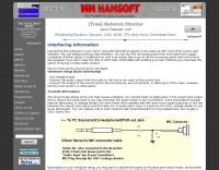 Demonstrates the fundamental principles for connecting a personal computer to a ham radio transceiver, specifically for utilizing sound card-based digital mode software like those in the MM Hamsoft suite. It details the basic hardware setup, emphasizing the use of shielded leads and proper audio routing from the radio's output to the sound card's input, and from the sound card's output to the radio's microphone or data input. The resource highlights the critical need for transmit attenuation, suggesting a 100:1 voltage divider to prevent overdriving the transmitter's audio stage, and mentions the optional addition of ferrite beads and decoupling capacitors for RFI mitigation. The guide also points to external resources for more detailed pin-outs and interface schematics, such as a specific QSL.net page, and recommends consulting the help files within MM Hamsoft programs for interfacing specifics. It underscores that while the process is straightforward, understanding the audio level management and proper cabling is key to successful operation. The author, VE5KC, provides practical advice drawn from common issues encountered by operators setting up digital mode stations.
 -
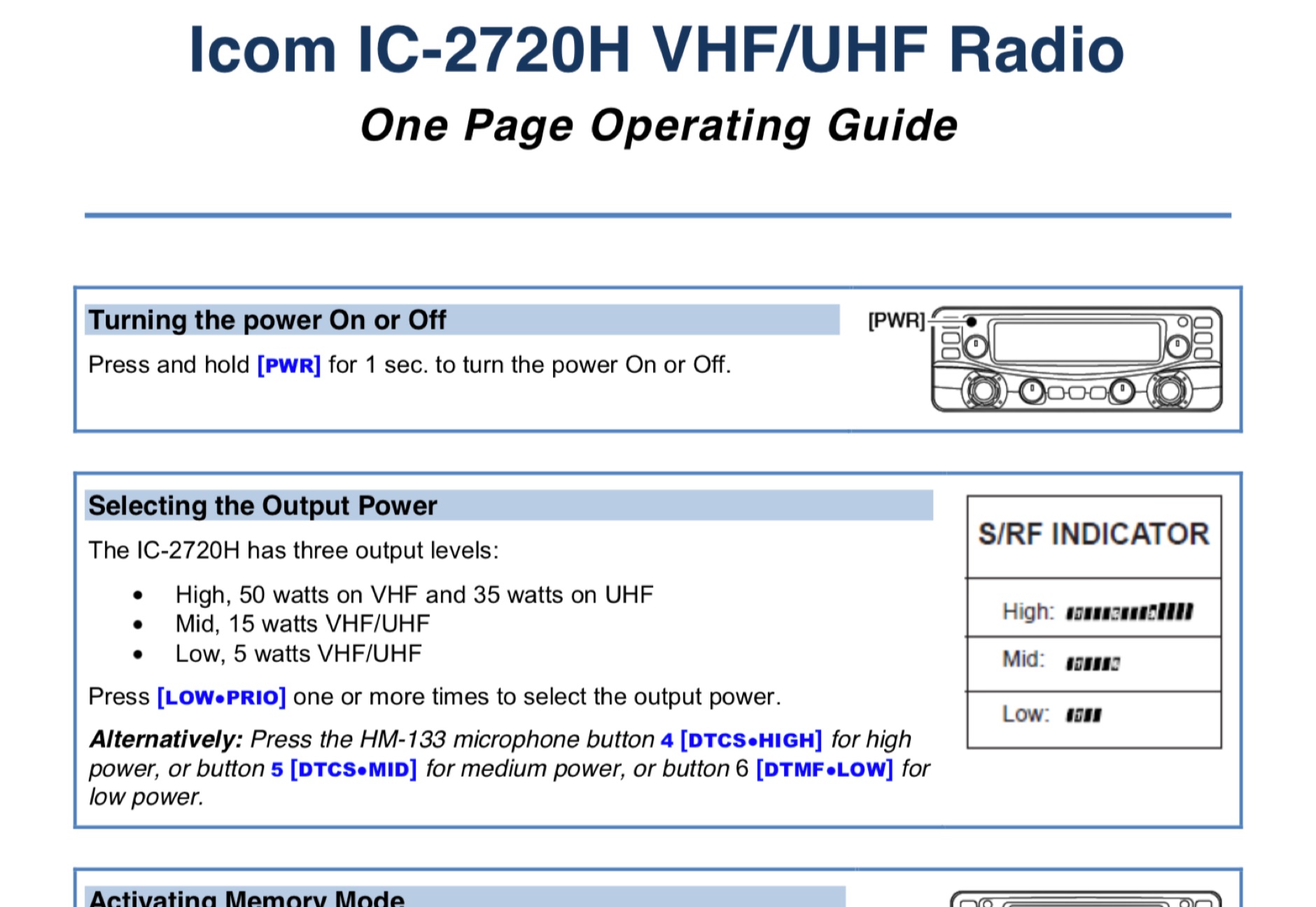 An operating guide for the com IC-2720H VHF/UHF Radio, includes Turning the power On or Off, Selecting the Output Power, Activating Memory Mode, Operating in Memory Mode
 -
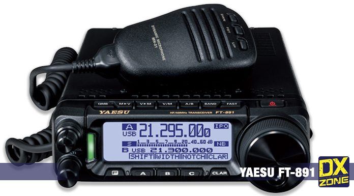 HF/50 MHz 100W All Mode Transceiver. The FT-891 provides stable 100 W (25 W AM) high power output
 -
 The N1HFX thermal cooling fan controller project details a practical circuit designed to manage cooling fan operation based on temperature, a common requirement for high-power amateur radio equipment. This build utilizes a **LM34** temperature sensor, providing a linear voltage output directly proportional to Fahrenheit degrees, simplifying the control logic. The circuit's core functionality involves a comparator that activates the fan when a preset temperature threshold is exceeded, ensuring efficient cooling and reducing unnecessary fan noise. This controller is particularly useful for amplifiers, power supplies, or transceivers that generate significant heat during operation. The design incorporates a _TIP120 Darlington transistor_ to drive the fan, capable of handling up to 5 amps, making it suitable for a range of fan sizes and current requirements. Field results indicate stable temperature regulation, preventing thermal runaway in enclosed environments. Construction involves readily available components, making it an accessible project for hams looking to optimize their station's thermal management.
 -
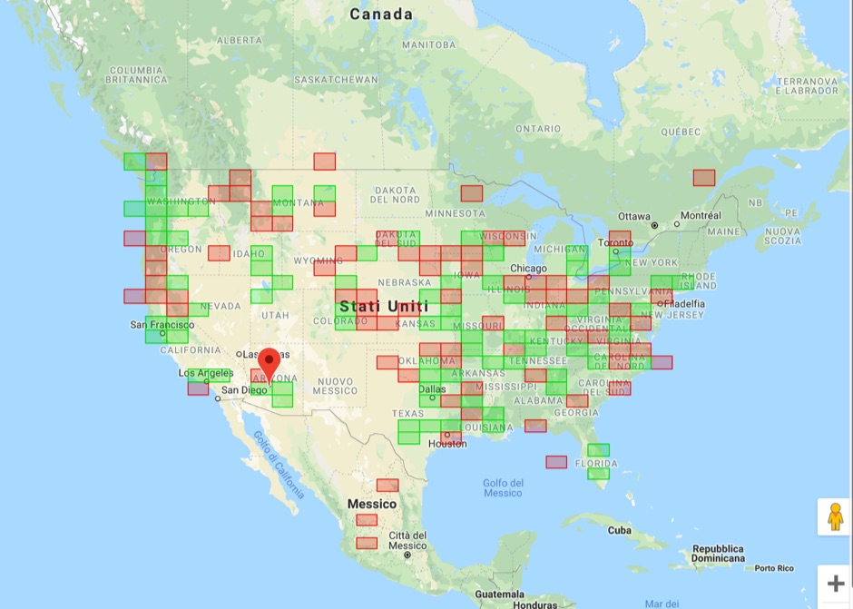 Upload an ADIF fiel and plot all worked grids in an online map. Support filtering by band, year and can export the output directly into a google map, or a google earth KML file
 -
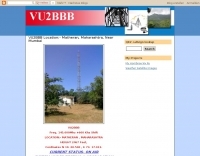 The VU2BBB repeater, located in Matheran, Maharashtra, commenced operations in the late 1980s, a significant undertaking by the Bombay Repeater Society. This repeater facilitates VHF and UHF communications for local amateur radio operators, providing extended range and improved signal reliability across challenging terrain. Its establishment marked a key development in regional amateur radio infrastructure, offering a crucial node for local nets and general QSO traffic. The repeater's operational parameters include specific input and output frequencies within the 2-meter band, typically utilizing a standard offset. CTCSS tones are often employed to mitigate interference and ensure selective access for authorized users, a common practice for repeaters in densely populated areas. Regular maintenance and upgrades ensure _VU2BBB_ remains a reliable asset for the amateur community, supporting emergency communications and daily amateur radio activities. The _Bombay Repeater Society_ continues to oversee its operation, reflecting a sustained commitment to local ham radio services.
 -
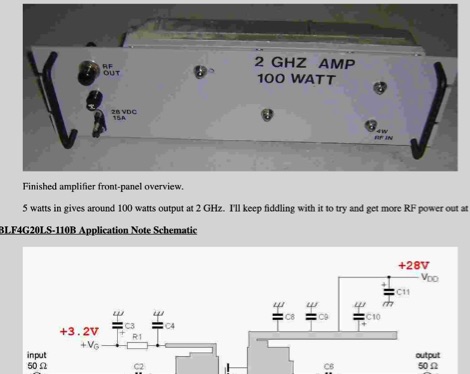
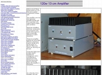 This amplifier uses two 60w Spectrian amplifier boards with the usual input and output hybrid coupler and combiner.
 -
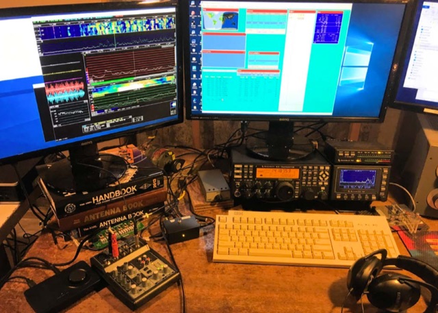 This article will explain a few of the ways author use an external SDR and Linrad to enhance his K3 experience. Linrad is one of many available SDR receiver programs. The same could be done with any radio that lets you access its IF frequency output. Article from NCJ Nov Dec 2019
 -
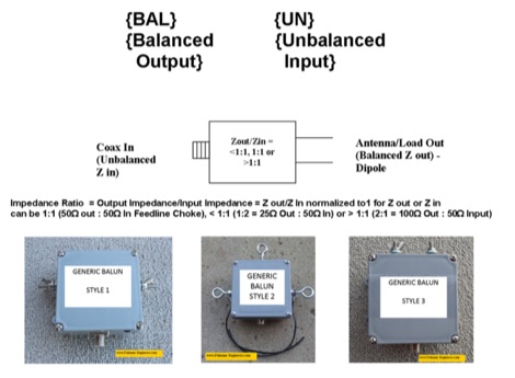 If you ever asked if you need an Unun or a Balun this article is for you. The right question should be do I need a feed line choke or an impedance transformer whose output is configured as balanced or as unbalanced. An impedance transformer can be configured as a voltage transformer or as a current transformer.
 -
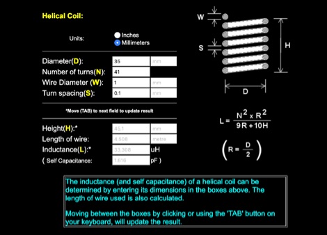 This online calculator will give as output the Inductance L of a coil, including the total lenght of the wire needed to wound the coil. As input, requires the Diameter, number of turns, wire diameter and turn spacing
 -
 Demonstrates the construction of a high-power 6-meter (50 MHz) amplifier, specifically designed for demanding modes like EME, TEP, and multiskip Es. It details the use of a _GU-43B_ tetrode in a grounded-cathode configuration, emphasizing the need for stabilized grid voltage and input capacitance compensation. The resource provides a comprehensive schematic, power supply design, and practical considerations for component sourcing, particularly for high-voltage and high-current sections. The builder achieved an output power of **1250 watts** with an anode current of 0.65 amperes and 3200 volts anode voltage. The article also covers the physical construction within a modified P6-31 enclosure, outlining the internal layout for RF and power supply sections, and includes photos of the completed unit. It highlights critical safety precautions for working with high voltages and reactive currents up to **20 Amperes** in the P-network.
 -
 Sixty-meter repeaters typically use a 1 MHz frequency separation between input and output, while 2-meter repeaters commonly employ a **600 kHz** split and 70-centimeter repeaters use a **5 MHz** offset. This article details the fundamental technical principles of amateur voice repeaters, explaining how they extend VHF/UHF communication range by receiving on one frequency and simultaneously retransmitting on another. It covers essential components such as receivers, transmitters, filters, and antennas, often situated on elevated locations for optimal coverage. The resource delves into the critical challenge of _desensing_—where the repeater's strong transmit signal overpowers its own receiver—and the engineering solutions employed, including antenna separation and the use of high-Q cavity filters. It also explores various control and timing systems, from basic squelch activation to more sophisticated microcontroller-based boards that manage functions like voice identification, time-out timers, and fault protection. Different access methods are discussed, including open access, toneburst, CTCSS subtone, and DTMF, each offering distinct advantages for managing repeater usage and mitigating interference. Furthermore, the article examines repeater linking, both conventional RF methods and modern internet-based solutions, highlighting how linking expands coverage and promotes activity across multiple repeaters or bands. It introduces less common repeater types such as 'parrot' repeaters, which use a single frequency and digital voice recording, and linear translators, capable of relaying multiple signals and modes simultaneously across different bands, often found in amateur satellites.
 -
 This article describes the construction of a high performance transmitter and receiver for SSB (voice) communication covering the 14MHz (20 meters) high frequency amateur radio band with output range 15 to 20 watts and a top audio sound quality both on transmit and receive.
 -
 Build a digital AC voltmeter to measure the output range from 0 to 150VAC with reasonable accuracy
 -
 Examples of absorbtive low-pass filters in which the unwanted high-frequency energy is separated from the wanted output and then dissipated in matched resistors
 -
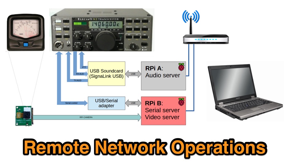 This is a page to detail how I remotely operate my Elecraft K2 HF transceiver via my home network. The method used should apply to pretty much any amateur transceiver that can be controlled by serial port.
 -
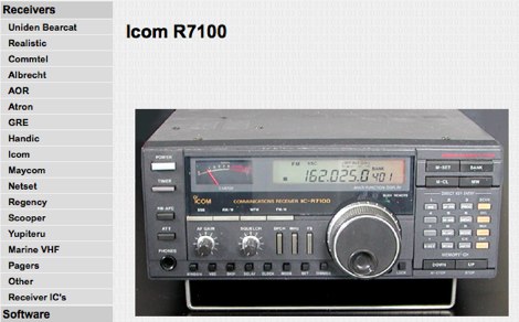 For a discriminator output in an Icom IC-R7100, some mechanical work is required.
 -
 A simple transmitter built into a small cat-food tin! It consists of a single 2N2222 crystal oscillator and runs about 100mw output, depending on the supplied voltage
 -
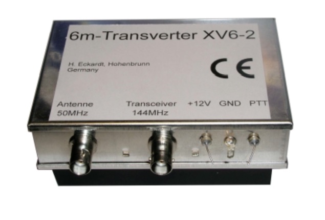
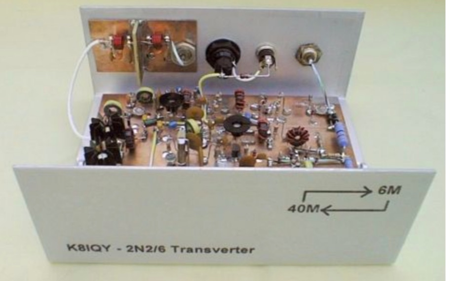 This project is a 40 meter to 6 meter CW "no tune" transverter using ten 2N2222 transistors and one 2N2907. The transverter requires 2 watts of drive from a 40 meter cw transceiver and outputs 2 watts on 6 meters.
 -
 A 0-30 MHz step attenuator, constructed from switchable Pi attenuation pads, provides a practical tool for evaluating receiver sensitivity and calibrating S-meters. The design utilizes readily available 5% tolerance resistors, with values derived from paralleled components to achieve specific attenuation steps. A schematic (Fig 1) illustrates the circuit, including PCB pad shielding, while a table details required and actual resistor values, along with percentage differences. Measurements of voltage input versus output at various frequencies are used to calculate dB attenuation, presented in a graph (Fig 4). The resource includes formulas for determining output voltage from a known input and a comprehensive 0-40 dB voltage multiplier table, which is crucial for precise signal level management. The project also references external attenuator calculators and equations for further study. Photos (1-3) provide visual guidance for the assembled unit, showing bottom, top, and front views. The project emphasizes the use of **Pi attenuation pads** and **receiver sensitivity** evaluation, offering a hands-on approach to RF signal management.
 -
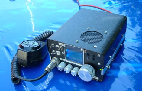
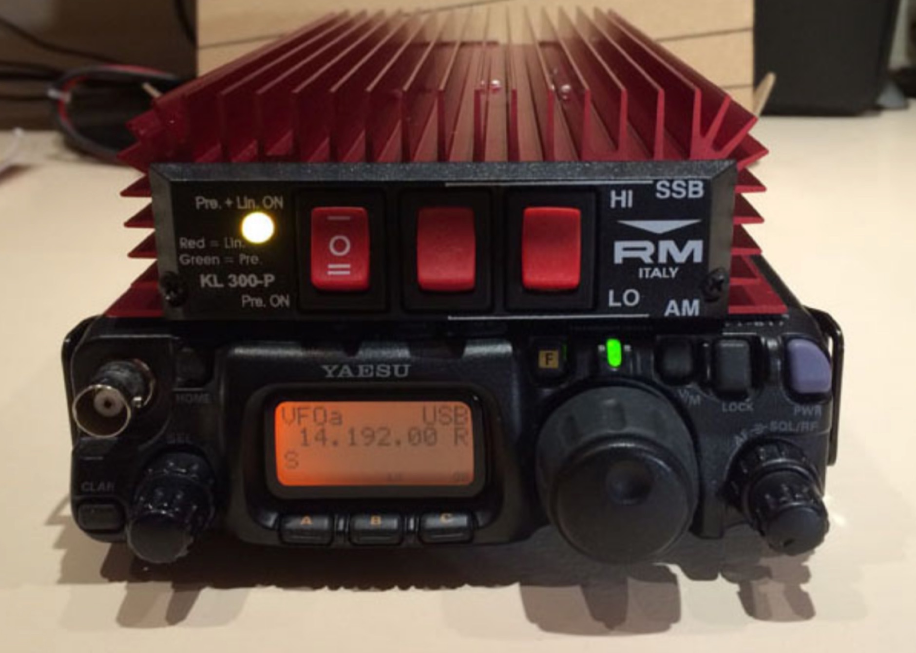 Direct experience of portable operations of the FT-817 transceiver by Yaesu and the small power amplifier by RM Italy with 300W output
 -
 Documents the operational experiences and technical insights of amateur radio station VA3STL, offering a firsthand account of various on-air activities and equipment. The blog features a detailed narrative of a **QRP transatlantic QSO** on 12m SSB, achieving a 55 report with 10W to a mobile station in Italy using a homebrew 90ft doublet antenna. It also introduces the _Ten-Tec 539_ QRP HF transceiver, a 10W output rig covering 80m through 10m, designed for portable operations and featuring DSP and dual VFOs. The resource also delves into historical radio technology, specifically the "Gibson Girl" survival radio, an emergency transmitter operating on 500kHz (and later 8280/8364 kHz) with a hand-cranked generator and kite-deployed antenna. This section explores its origins from German designs and its use during World War II, including its distinctive curved shape for ergonomic hand-cranking. Further historical content includes a visit to Signal Hill in St. John's, Newfoundland, commemorating Marconi's reception of the first transatlantic radio signal in 1901. The post describes the Cabot Tower exhibit and the VO1AA station, highlighting the site's significance despite the thick fog during the visit. It also showcases a homebrewed _Marconi-style straight key_ by WB9LPU, crafted to celebrate the centenary of Marconi's achievement.
 -
 The ZS1J/B beacon operates on 28.2025 MHz with 5 Watts output to a half-wave, end-fed vertical antenna, initially installed in 1977 as ZS5VHF near Durban. The 10-meter transmitter is a modified 23-channel CB radio, and the identification keyer uses a diode matrix unit with TTL ICs from the same era. After relocation to Plettenberg Bay in 1993, the beacon has been in continuous service, with additional QRP transmitters later installed for other bands. In 1994, a single-transistor, 80-meter, 0.5-watt QRP transmitter with a half-wave dipole was added on 3586 kHz, followed by a 160-meter, 0.5-watt unit on 1817 kHz. A 30-meter, 0.5-watt transmitter was installed in 1996, operating on 10.124 MHz. In 2002, a 40-meter QRRP beacon on 7029 kHz, with an output of 100 microwatts, achieved DX reports up to 1100 km from ZS6UT in Pretoria. Best DX reports for the 80m and 160m beacons came from 9J2BO.
 -
 Converting a computer\'s VGA output for an oscilloscope
 -
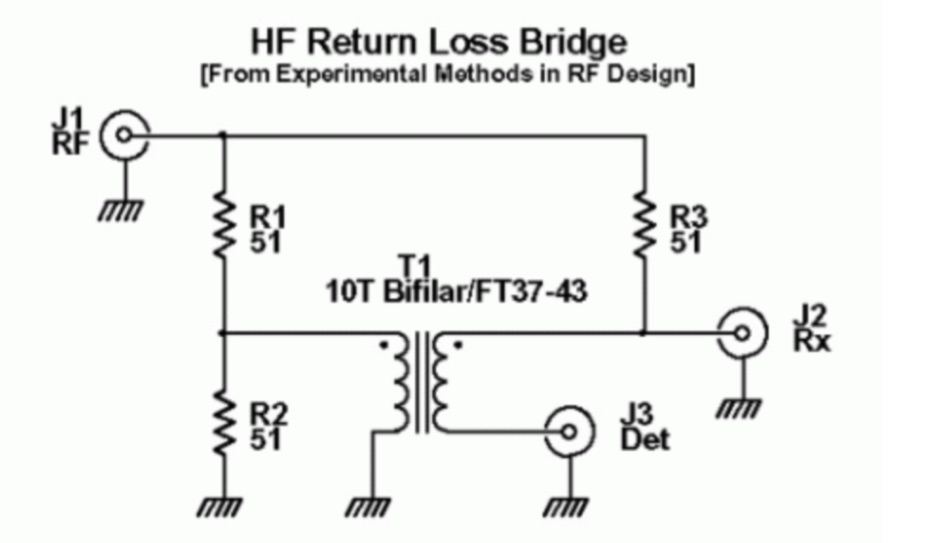 This Return Loss Bridge has been designed to characterize the input impedance of a receive strip, and the output impedance of a transmit strip
 -
 A top band shortened vertical antenna project. This project includes drawing and MMANA-GAL output screens.
 -
 DataBridge wireless RF modem modules facilitate point-to-point data transmission, supporting analog, digital, and serial RS232 UART signals. These modules are engineered for robust wireless communication, offering a reliable solution for various industrial and amateur radio applications requiring secure data links. The product line includes specific models designed for different frequency ranges and power outputs, ensuring compatibility with diverse operational requirements. Each module integrates advanced RF technology to maintain signal integrity over distance, crucial for remote monitoring and control systems. The design emphasizes ease of integration, allowing users to quickly deploy wireless data links without extensive configuration. Key features encompass low power consumption and a compact form factor, making them suitable for embedded systems and portable devices.
 -
 One common semiconductor material, silicon, is far more widely used in electronics than germanium, partly because it can operate at much higher temperatures. Semiconductors are crystalline materials with electrical resistivity values between conductors and insulators, whose conductivity can be altered through _doping_ with impurities like arsenic or phosphorous to create N-type (excess electrons) or P-type (electron vacancies) materials. Semiconductor devices, such as diodes, transistors, and integrated circuits, leverage these properties to control electron flow in circuits. A diode, a two-terminal device with an anode and cathode, primarily permits current flow in one direction, making it useful as a rectifier to convert AC to DC. Specialized diodes include Zener diodes for voltage regulation and Light-Emitting Diodes (LEDs) that produce light when current passes through them. Logic circuits, fundamental to digital electronics, have binary inputs and outputs, performing functions like AND, OR, and NOT gates, and can be constructed from various binary devices including solid-state diodes and transistors. A transistor is an active semiconductor device with at least three terminals (base, emitter, collector), capable of amplifying current. Integrated circuits (ICs), often called chips, are electronic circuits built on a semiconductor substrate, typically silicon. ICs are classified by transistor type (bipolar or MOS) and integration scale: Small-Scale Integration (SSI) with fewer than 10 transistors, Medium-Scale Integration (10-100), Large-Scale Integration (LSI) with 100-1,000, and Very-Large-Scale Integration (VLSI) with more than **1,000** transistors. ICs can be analog, digital, or hybrid, offering virtually limitless functions.
 -
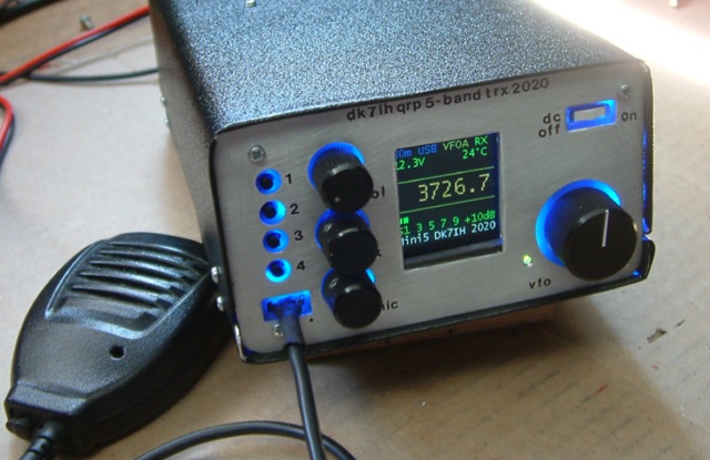 Gimme Five reloaded, a compact 5 band QRP SSB transceiver in SMD technology. This unit covers 5 bands within the amateur radio spectrum (3.5, 7, 14, 21 and 28 MHz). Receiver is a single conversion unit with an interfrequency of 9 MHz. Transmitter uses 5 stages and has got a power level of 10 watts PEP output.
 -
 The Baofeng UV-5R handheld transceiver, introduced around 2012, operates across the 2-meter (144-148 MHz) and 70-centimeter (420-450 MHz) amateur bands, offering dual-band receive and transmit capabilities. This review provides an early assessment of the radio's form factor, user interface, and general performance, noting its compact size and the inclusion of a **VFO/Memory mode** button for frequency management. The device supports both FM and narrow FM modes, with a reported power output of 4 watts on VHF and 3 watts on UHF, making it suitable for local simplex and repeater operations. Key features discussed include its 128-channel memory capacity, a built-in VOX function, and a **DTMF keypad** for tone dialing and repeater access. The review highlights the radio's ability to scan frequencies and memories, along with a dual-watch function allowing simultaneous monitoring of two frequencies. Battery life is addressed, with the standard 1800 mAh Li-ion pack providing several hours of operation depending on transmit usage. Initial impressions cover the radio's construction and the clarity of its LCD display, which shows both A and B band frequencies.
 -
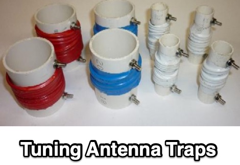 The problem with making your own trapped HF antennas is usually getting the coaxial traps tuned to frequency. This article explains a method using a RF signal generator at +10dBm output into the coaxial trap.
 -
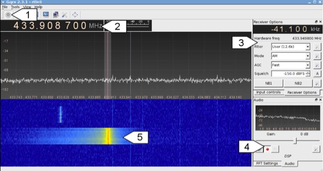 Analyzing 433 MHz radio signals from common wireless devices, such as temperature sensors and remote controls, involves understanding **On-Off Keying (OOK)** modulation. This resource details the process of capturing these signals using a Software Defined Radio (SDR) like Gqrx and then visually inspecting the captured audio data in a sound editor such as Audacity. It differentiates between **Pulse Width Modulation (PWM)** and Pulse Position Modulation (PPM) encoding schemes, illustrating how to identify and decode binary data by eye based on pulse and gap durations. The article provides a step-by-step walkthrough for decoding a wireless thermometer's data, correlating bit patterns with known temperature, humidity, and channel values. It also demonstrates decoding an RF remote control's button presses, highlighting the constant and varying parts of the transmitted packets. The content further introduces automated decoding using tools like RTL_433, explaining its capabilities in parsing various device protocols and showing how to interpret its output, including modulation type and decoded data. Specific examples include analyzing Prologue sensor protocol specifications from RTL_433's source code and noting common operating frequencies like 433.92 MHz in Europe and 915 MHz in the US.
 -
 The XV4-10 is a linear transverter for the 4m band to be used with a 10m transceiver. Input frequency 29-30 MHz, output frequency 69.5-70.5 MHz
 -
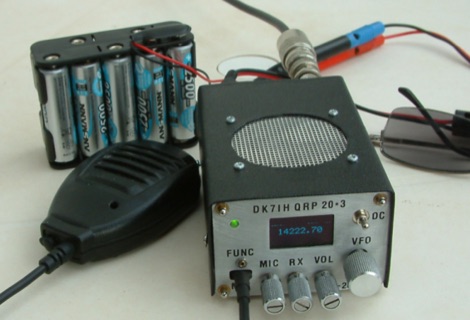 DK7IH QRP transceiver for 14 MHz. This small and compact home made transceiver with a max power output of 5W, the VFO module is based on the clock oscillator chip Si5351A by Silicon Labs ATmega168 and OLED 1306
 -
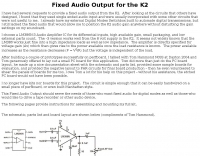 W3FPR fixed level AF output fot the Elecraft K2
 -
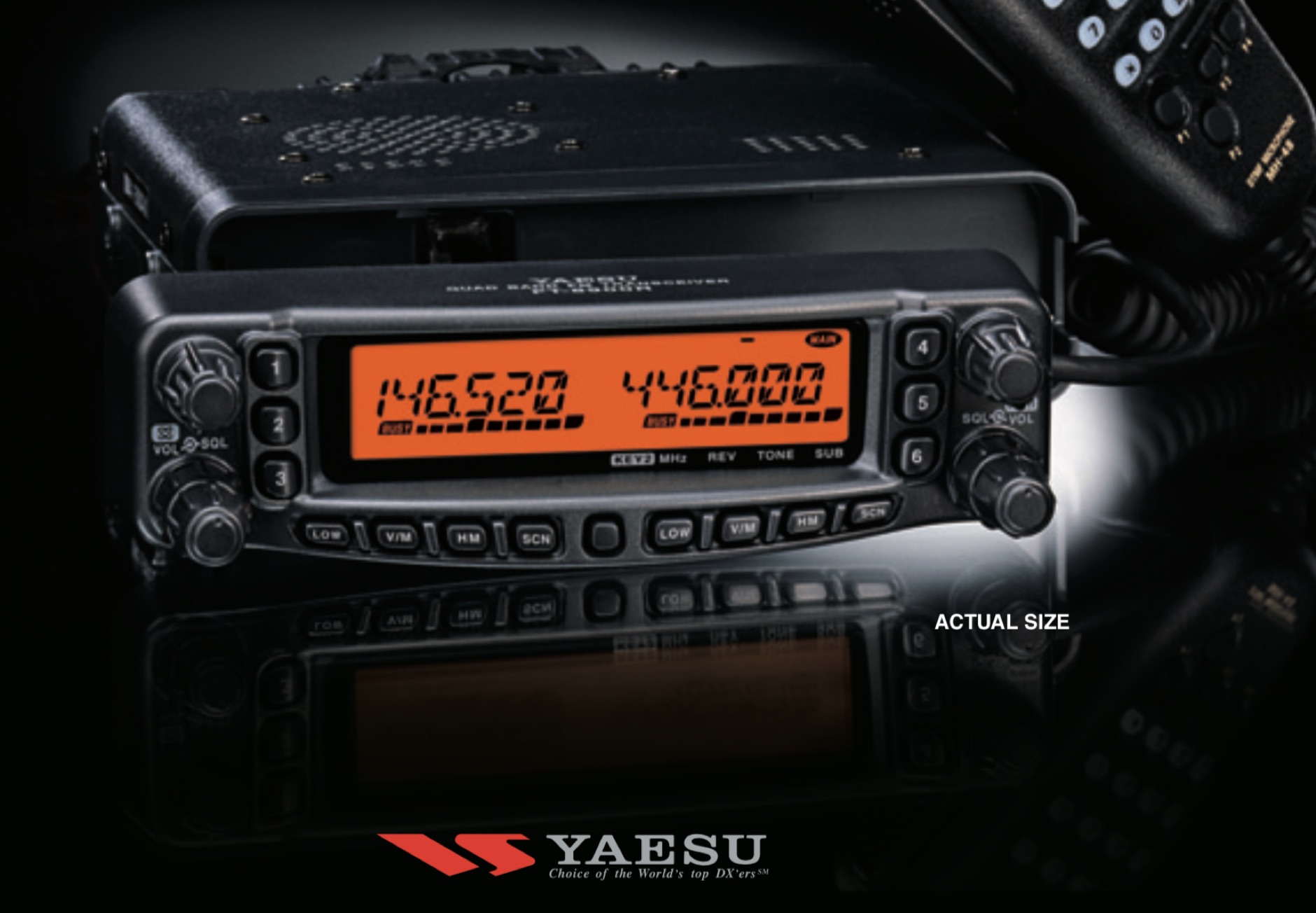 A review of the Yaesu FT-8900r 29/50/144/430 MHz FM Transceiver, providing 50 Watts of power output on the 29/50/144 MHz Amateur bands, and 35 Watts on the 430 MHz band.
 -
 How to modify your scanner or receiver with a discriminator output. If you want to decode and monitor digital (FSK and PSK) systems seriously, a discriminator tap is an absolute prerequisite.
 -
 Documents S21RC's construction of an impedance transformer harness for a VHF/UHF cross yagi, utilizing 20m of _RG179_ cable. Details the creation of a DIY RF sampler with a -50dB sampling output, primarily for measuring HF radio PA section output with a Spectrum Analyzer, also applicable for _Pure Signal_ transmission. Chronicles the deployment of a 200m long beverage antenna for the _S21DX IOTA_ operation in 2022, positioned 2m above ground. Discusses the construction of a 3-element short beam for 10m to replace a previous 2-element antenna, with assistance from S21DW. Provides guidance on operating cheap _PA-70_ and _PA-100_ type Chinese SSPAs using IRF530 MOSFETs, emphasizing the necessity of a final LPF. Outlines the design and construction of a fully isolated interface for radio-to-computer connections, supporting various digital modes with isolated ground, audio transformers for IN/OUT, optical isolation for CAT/CIV, and isolated PTT/COS lines. Includes a log of software updates, such as the _HMI/TFT for NX8048K070_ and _2.1.14 Lite_ release with bug fixes for PEP hold and gradual watt decay.
 -
 Amateur radio repeaters, often designated by an "R" number like _R6_ or _R5_, serve as crucial infrastructure for extending VHF/UHF communications range. This resource from Essex Ham explains the fundamental concept of a repeater, detailing how it receives on one frequency and simultaneously retransmits on another, typically with a 600 kHz offset for 2-meter repeaters. Understanding the input and output frequencies, along with the required CTCSS tone, is essential for successful access, ensuring your signal is processed and relayed across a wider service area. The article clarifies the importance of using the correct _CTCSS_ (Continuous Tone-Coded Squelch System) tone, often referred to as a sub-audible tone, to activate a specific repeater. It also touches upon the concept of _simplex_ operation versus repeater use, highlighting the benefits of repeaters for mobile and handheld transceivers. Proper operating procedures, such as listening before transmitting and keeping transmissions concise, are emphasized to maintain good amateur practice on shared repeater assets.
 -
 256 memories enable the _AT-AUTO_ to recall settings across multiple bands, making it efficient for operators who frequently change frequencies. The tuner is compatible with various antennas and amplifiers, such as the Mercury LUX, and integrates seamlessly with radios like the FLEX 6400 using an RS232-USB connection. This integration allows the tuner to follow frequency changes without additional input, enhancing operational efficiency. Despite being out of production, the _AT-AUTO_ remains supported by Kessler Engineering, which offers firmware updates and repair services. The tuner features a cross-needle SWR meter, providing quick visual feedback during tuning. It also includes a QRO keyline circuit to protect amplifiers during tuning. Users appreciate the tuner's ability to track radios via CAT control, avoiding automatic tuning during QSOs, a common issue with other models. The _AT-AUTO_ is praised for its durability and performance, with many users noting its reliability over years of use. Its ability to handle legal limit power and its balanced line output make it a versatile choice for serious operators. Although it lacks some features like multiple coax outputs found in other models, its robust build and continued support make it a valuable tool for HF enthusiasts.
 -
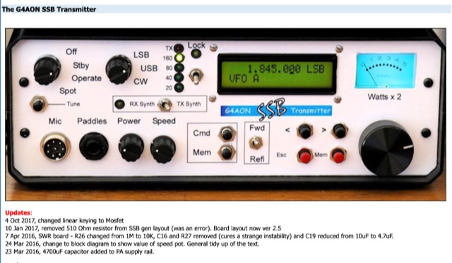 This transmitter covers the 160, 80, 40 and 20 metre bands and provides both SSB and properly generated CW. The CW side of this transmitter is not compromised and produces excellent CW. On SSB the audio has been tailored to provide a rising response to 3 KHz, with a sharp drop above that frequency. There is RF speech clipping to both provide more "punch" and to limit the peak output.
 -
 This will show you how to add a RF power amplifier to your Proxim Symphony for under $50. The cost is reduced by using the existing components on the Symphony, such as the PIN diode switch, and just inserting a higher power final amplifier. Increase the RF output power of your wireless network card to 1 Watt.
 -
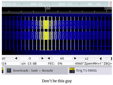 Start by getting your audio levels sorted out, Having your levels correct is critical to maximum effectiveness in both TX quality and also for being able to decode signals properly. Guide to Filters and other Rig Settings to optimize your output signal
 -
 The _G3TSO_ Mobile Antenna Page details construction and tuning methods for mobile antennas operating across **10 to 160 metres**. The content describes a Hustler-based design, optimized for RF performance and vehicle speeds, featuring centre loading. For optimal operation on various bands, the loading coil placement requires clearance from the vehicle body. Antenna resonance is critical for efficient mobile operation. A mobile antenna's base impedance may be as low as 27 ohms, requiring specific matching to achieve maximum radiation, as a minimum SWR at the transmitter does not always indicate resonance or maximum output. Tuning involves physical adjustment of antenna length to achieve resonance at the operating frequency. The _G3TSO_ page outlines a tuning procedure utilizing a low-power signal source and a field strength meter to identify maximum radiation before impedance matching. Loading coil placement, either at the base, center, or top of the antenna, influences radiation efficiency and mechanical stability for mobile installations. Centre-loaded whips, such as the Hustler design, offer a compromise between efficiency and stability, often for single-band operation. Helically wound antennas, including those for **28 MHz**, may present base impedances around 17 ohms, resulting in a 3:1 SWR at resonance. Low resistance grounding at the antenna base is also specified for optimizing performance and minimizing RFI during mobile operation. DXZone Focus: Mobile | Any | Antenna Tuning | HF
 -
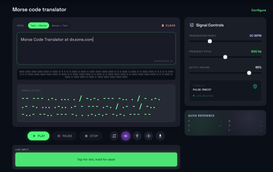 The morsecodeworld.org web application provides an online Morse code decoder and encoder, facilitating real-time conversion between text and International Morse code. It supports adjustable transmission speed (Words Per Minute), sidetone frequency pitch (Hz), and output volume, allowing users to customize their learning and practice environment. The tool includes a quick reference chart for the Morse alphabet and focuses exclusively on International Morse, aligning with contemporary amateur radio licensing and on-air practices, distinguishing it from historical American Morse code. This web-based utility enables users to type text for encoding into Morse audio or paste Morse code for decoding into plain text, offering immediate feedback on timing and character spacing. It supports both visual and auditory learning by providing adjustable parameters for speed and tone. The platform is designed for self-assessment, encouraging users to practice copying and sending, and to identify and correct common errors in character recognition and timing.
 -
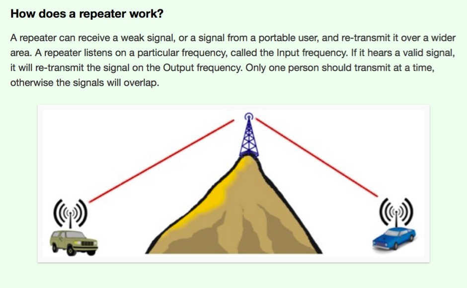
 Explains the fundamental purpose of a repeater, detailing how these automated relay stations overcome distance and terrain limitations for VHF/UHF communications. It traces the historical development from early Bell Telephone Labs "relay" stations in 1922 to Art Gentry, W6MEP's, pioneering K6MYK amateur radio repeater in the mid-1950s, which remains active today. The resource clarifies the distinction between simplex and duplex operation, including the unique function of a "parrot repeater" for single-frequency recording and playback. Delving into the internal workings, the guide breaks down a repeater into its core components: the antenna system, feedline (often _Heliax_ or hardline for minimal loss), duplexer, receiver, transmitter, and controller. It emphasizes the critical role of the duplexer in preventing receiver desensitization by isolating transmit and receive signals, even with distinct frequencies. The discussion highlights the importance of high-performance, durable antennas and low-loss feedlines, citing examples of equipment installed in the 1960s and 1970s that are still in perfect working order. Operating a repeater is also covered, with an explanation of frequency offset (e.g., the 600 kHz standard for 2 meters) and the function of _CTCSS_ (PL tone) for access. It outlines standard input/output offsets for various bands, from 6 meters to 23 centimeters, while noting regional variations. The guide also touches on features like autopatch and Digital Voice Recorders (DVRs), providing a solid foundation for understanding repeater technology and usage.
 -
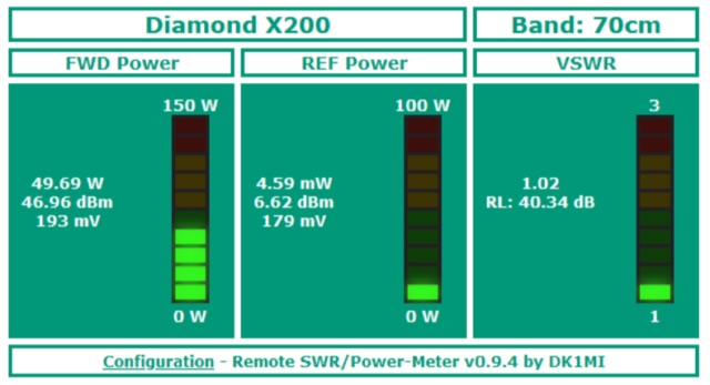 Remotely monitor the output power and SWR of your station via a web browser. WT32/ESP32 based project, combined with a directional coupler setup. It reads two voltages which are supplied by the directional couplers. From these, the respective power is calculated with the help of a calibration data table to be created by the user.
 -
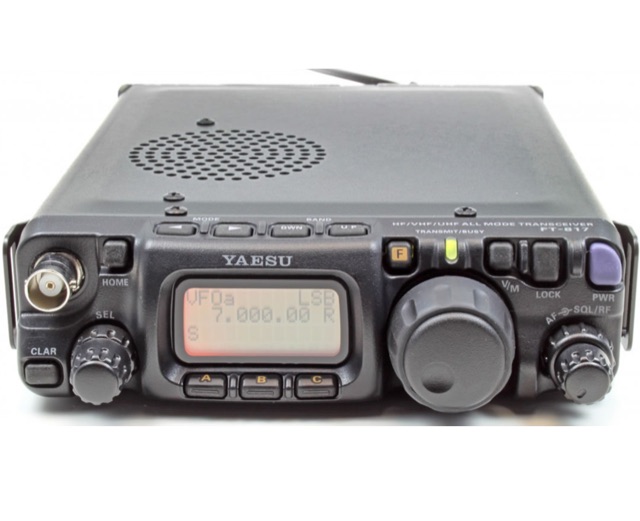 Reflected power and VSWR Metering on Yaesu FT-817, and proper interpretation of real values. The power output meter it is a relative indicator of the antenna match that the radio is experiencing. Reference table and how correctly read the values of the Yaesu internal meter.
 -
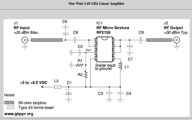
 Modification to an old cellular phone base station modules, with a fairly reduced output power (10 watts or so), the stock power amplifier modules will cover the 2.3 GHz and 2.4 GHz amateur radio bands.