Search results
Query: transmitter
Links: 256 | Categories: 5
-
 The Doppler Effect allows the distance between a satellite transmitting from space and a radio receiver on the ground to be measured by observing how the frequency received from the satellite transmitter changes as the satellite approaches, passes overhead, and moves away.
 -
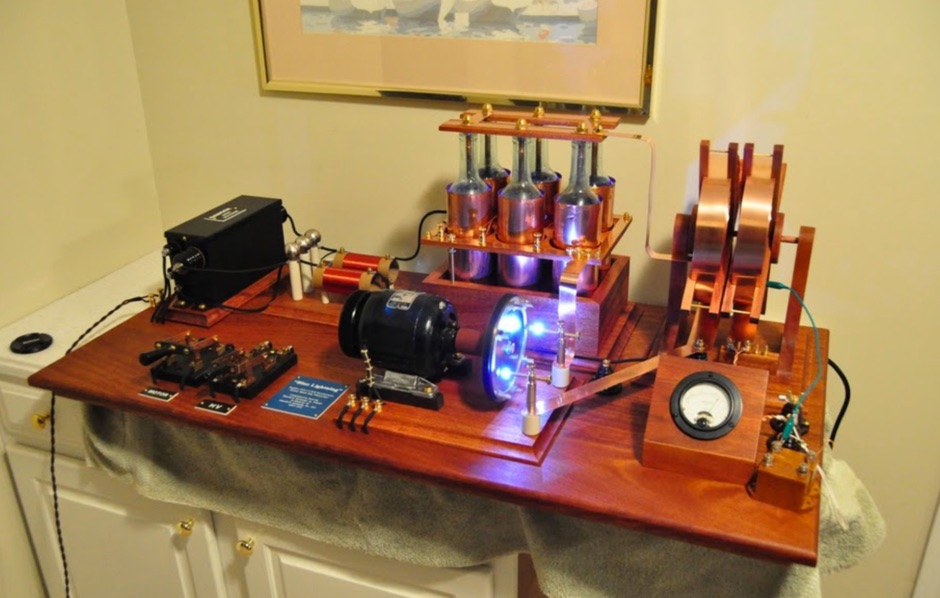 The details of the spark gap transmitter and its history: how it was invented, developed and used.
 -
 ELENOS is the leader company for fm transmitters, amplifiers, radio broadcast equipment and custom systems.
 -
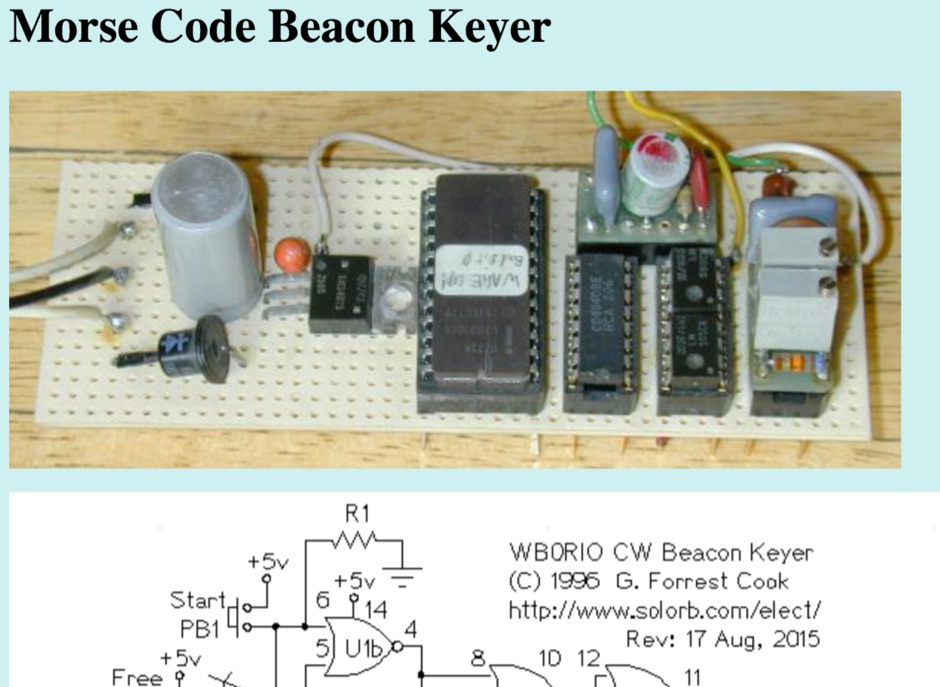 This circuit stores a morse code message as bits in an EPROM chip, the message controls a relay that keys a CW morse code transmitter. An Arduino processor can also be used in place of this circuit, that eliminates the need to build the circuit and program an EPROM.
 -
-
 A homebrew radio transmitter project, based and inspired by the original 30 Watts input on 80 50 and 15 meters band transmitter by W11CP
 -
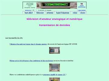
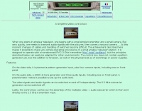 When one starts in amateur television, one begins with a small simple transmitter and a small camera. But very quickly, one needs to transmit audio signals with the pictures, then comes a second camera
 -
 Sixty-meter repeaters typically use a 1 MHz frequency separation between input and output, while 2-meter repeaters commonly employ a **600 kHz** split and 70-centimeter repeaters use a **5 MHz** offset. This article details the fundamental technical principles of amateur voice repeaters, explaining how they extend VHF/UHF communication range by receiving on one frequency and simultaneously retransmitting on another. It covers essential components such as receivers, transmitters, filters, and antennas, often situated on elevated locations for optimal coverage. The resource delves into the critical challenge of _desensing_—where the repeater's strong transmit signal overpowers its own receiver—and the engineering solutions employed, including antenna separation and the use of high-Q cavity filters. It also explores various control and timing systems, from basic squelch activation to more sophisticated microcontroller-based boards that manage functions like voice identification, time-out timers, and fault protection. Different access methods are discussed, including open access, toneburst, CTCSS subtone, and DTMF, each offering distinct advantages for managing repeater usage and mitigating interference. Furthermore, the article examines repeater linking, both conventional RF methods and modern internet-based solutions, highlighting how linking expands coverage and promotes activity across multiple repeaters or bands. It introduces less common repeater types such as 'parrot' repeaters, which use a single frequency and digital voice recording, and linear translators, capable of relaying multiple signals and modes simultaneously across different bands, often found in amateur satellites.
 -
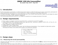 A transmitter project for the 136 kHz band by IK2PII
 -
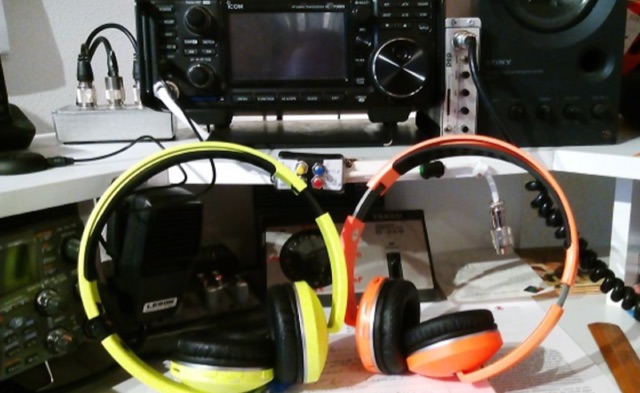 It is possible to add a very small Bluetooth transmitter to the 3.5mm headphone jack and then use a pair of Bluetooth headphones around the shack. In this article Author provides some tips on choosing the proper Bluetooth interface.
 -
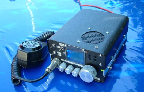 This article describes the construction of a high performance transmitter and receiver for SSB (voice) communication covering the 14MHz (20 meters) high frequency amateur radio band with output range 15 to 20 watts and a top audio sound quality both on transmit and receive.
 -
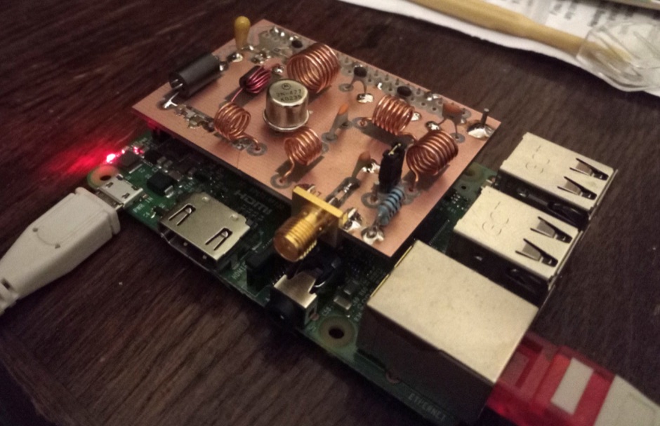 How to limit unwanted harmonics from your raspberry Pi radio transmitter by introducing filters.
 -
 Producers of custom name tags, luggage tags, club badges, Employee Name Tags, Special Event Badges, but also Comtech Amateur Radio Television Transmitters and Receivers D480 filters, Video cameras and accessories.
 -
 Receivers and transmitters by Collins , Drake , Hallicrafters , Hammarlund , National Receivers
 -
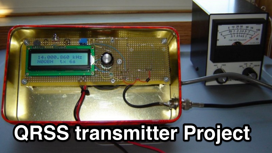 The N0QBH QRSS project page, a couple of projects using available kits for improved frequency and timing stability. A configurable DDS VFO 100mW transmitter with LCD display and a modified Hans Sommers 40m 100mW transmitter
 -
 An article on the restoration of a Gates Radio M-5078 Commercial HF AM transmitter by John LeVasseur, W2WDX
 -
 A microprocessor based interface designed to go between a standard Morse code key and a radio transmitter. The circuit receives a signal from the key, processes it, and re-transmits it to the radio.
 -
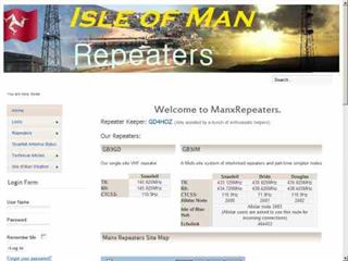 Isle of Man Repeaters maintained by David Osborn GD4HOZ this site covers the VHF repeater GB3GD and UHF internet linked 70cm repeater GB3IM. Using Allstar software for linking GB3IM is the only site in the uk to have three transmitters. Supported by the Isle of Man Amateur Radio Society
 -
 The PI6ATV repeater, operating on 10.475 MHz, serves the amateur television community by providing both analog and digital DVB-S2 services. Recent updates include user-adjustable Symbol Rate settings via Webcontrol, allowing operators to optimize their digital ATV transmissions for various conditions. This functionality, implemented on December 13, 2022, enables dynamic configuration of the digital stream. Significant technical milestones include the return of the analog ATV transmitter on 10.475 MHz, featuring a newly constructed liquid-cooled final amplifier by Edwin PD2EBH. This restoration on September 6, 2020, followed an 18-month hiatus, ensuring continued support for traditional analog ATV enthusiasts. The repeater's transition to DVB-S2 modulation, initiated on December 20, 2018, addressed capacity limitations of the previous DVB-S setup. This change from 20 MS/s with FEC 3/4 to DVB-S2 allowed for more efficient data handling, accommodating multiple channels within the available bandwidth and enhancing the overall digital ATV experience.
 -
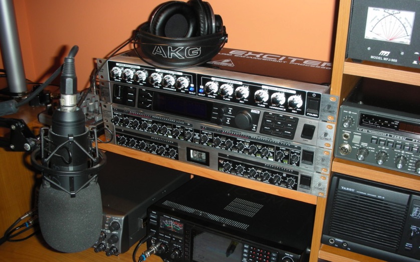 Sending the Audio from the Receiver to the Recorder, from the Recorder to the EQ, and sending the Audio from the EQ or Recorder to the Transmitter
 -
-
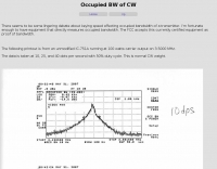 About keying speed affecting occupied bandwidth of a transmitter.
 -
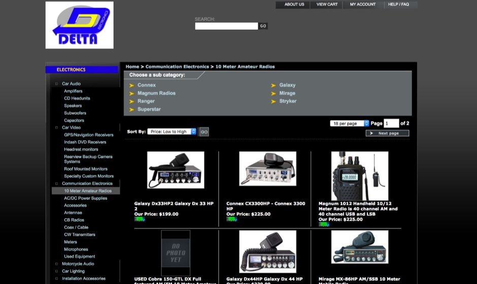 Delta Electronics, Inc. NY USA, family owned and operated selling all varieties of consumer electronics including 10 meter amateur radios, antennas, accessories, microphones, cw transmitters, coax cables and more
 -
 A simple transmitter built into a small cat-food tin! It consists of a single 2N2222 crystal oscillator and runs about 100mw output, depending on the supplied voltage
 -
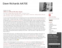
 Documents the operational experiences and technical insights of amateur radio station VA3STL, offering a firsthand account of various on-air activities and equipment. The blog features a detailed narrative of a **QRP transatlantic QSO** on 12m SSB, achieving a 55 report with 10W to a mobile station in Italy using a homebrew 90ft doublet antenna. It also introduces the _Ten-Tec 539_ QRP HF transceiver, a 10W output rig covering 80m through 10m, designed for portable operations and featuring DSP and dual VFOs. The resource also delves into historical radio technology, specifically the "Gibson Girl" survival radio, an emergency transmitter operating on 500kHz (and later 8280/8364 kHz) with a hand-cranked generator and kite-deployed antenna. This section explores its origins from German designs and its use during World War II, including its distinctive curved shape for ergonomic hand-cranking. Further historical content includes a visit to Signal Hill in St. John's, Newfoundland, commemorating Marconi's reception of the first transatlantic radio signal in 1901. The post describes the Cabot Tower exhibit and the VO1AA station, highlighting the site's significance despite the thick fog during the visit. It also showcases a homebrewed _Marconi-style straight key_ by WB9LPU, crafted to celebrate the centenary of Marconi's achievement.
 -
 The ZS1J/B beacon operates on 28.2025 MHz with 5 Watts output to a half-wave, end-fed vertical antenna, initially installed in 1977 as ZS5VHF near Durban. The 10-meter transmitter is a modified 23-channel CB radio, and the identification keyer uses a diode matrix unit with TTL ICs from the same era. After relocation to Plettenberg Bay in 1993, the beacon has been in continuous service, with additional QRP transmitters later installed for other bands. In 1994, a single-transistor, 80-meter, 0.5-watt QRP transmitter with a half-wave dipole was added on 3586 kHz, followed by a 160-meter, 0.5-watt unit on 1817 kHz. A 30-meter, 0.5-watt transmitter was installed in 1996, operating on 10.124 MHz. In 2002, a 40-meter QRRP beacon on 7029 kHz, with an output of 100 microwatts, achieved DX reports up to 1100 km from ZS6UT in Pretoria. Best DX reports for the 80m and 160m beacons came from 9J2BO.
 -
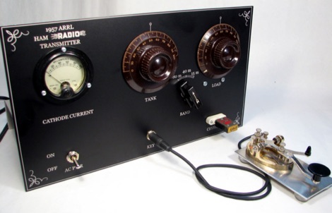
 Station QRP presents various **circuit diagrams** for constructing low-power AM vacuum tube shortwave transmitters, catering to enthusiasts interested in vintage radio technology. The resource details schematics ranging from simple to more complex designs, enabling hams to build their own QRP AM transmitters for operation on frequencies like 6.925 kHz AM. It emphasizes the use of vacuum tubes, providing a technical foundation for understanding and replicating classic shortwave broadcasting methods. The content is geared towards those who enjoy the hands-on aspect of electronics and the unique characteristics of tube-based RF circuits. Building these transmitters allows operators to experience the nostalgia of early shortwave radio, with the site specifically mentioning a pioneer station on 6.925 kHz AM. The designs facilitate experimentation with low-power AM transmission, offering practical application for homebrew projects. The focus on QRP (low power) operation aligns with a segment of the amateur radio community that values efficiency and minimalist setups, providing a distinct alternative to modern solid-state transceivers.
 -
 This module is an analogue and digital SWR and power meter/monitor, designed to replace analogue SWR and power metering in an AM Transmitter project.
 -
 Fox Controller, designed by VE2JX and VE2EMM includes schematic diagram to build the transmitter.
 -
 Chronicles the operational history of Cullercoats Radio, established in 1906 under _Marconi_ license, detailing its initial use of a spark-gap transmitter feeding a **200-foot** wooden mast. Documents the station's transition in 1915 to Marconi Wireless and a 1929 upgrade to a valve-type transmitter. Explains its later role as a British Telecom (BT) Maritime Radio Station, callsign GCC, serving as a receiving site with transmitting aerials at Hartley. Highlights the demolition of the commercial mast in 2000 and the site's subsequent sale. Features the Tynemouth Radio Club (GX0NWM) operating special event stations like GB4MPC for International Marconi Day from Marconi Point. Includes a historical QSL card confirming a QSO on **7.016 MHz** in 1936.
 -
 Low-frequency (LF) radio time signals, operating primarily in the 40–80 kHz range, are broadcast by national physics laboratories for precise clock synchronization. Transmitters like **JJY** (40 kHz, 50 kW; 60 kHz, 50 kW), RTZ (50 kHz, 10 kW ERP), MSF (60 kHz, 15 kW ERP), WWVB (60 kHz, 50 kW ERP), RBU (66.66 kHz, 10 kW), and DCF77 (77.5 kHz, 50 kW) cover vast geographic areas, often several hundred to thousands of kilometers. LF signals offer distinct propagation advantages over higher-band transmissions such as GPS. Their long wavelengths (3–6 km) enable effective diffraction around obstacles like mountains and buildings. The ionosphere and ground act as a waveguide, eliminating the need for line-of-sight and allowing a single powerful station to cover extensive regions. Ground wave propagation minimizes ionospheric variability effects on transmission delay, and signals penetrate most building walls effectively. Robust and low-cost receivers, often priced at 20–30 USD/EUR, are widely used in radio clocks. These receivers typically comprise a tuned ferrite core antenna, a receiver IC (e.g., Atmel T4227, U4223B, MAS1016) for amplification and AM detection, and a microcontroller for decoding the time signal and phase-locking a local clock. Specific components for DCF77, MSF, and WWVB are readily available from vendors like HKW Elektronik and Ultralink.
 -
 A Fox transmitter by VE2EMM with construction details part list and schematic diagram
 -
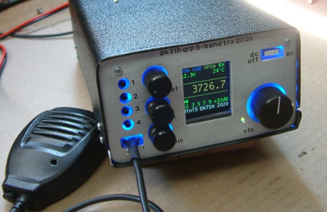 Gimme Five reloaded, a compact 5 band QRP SSB transceiver in SMD technology. This unit covers 5 bands within the amateur radio spectrum (3.5, 7, 14, 21 and 28 MHz). Receiver is a single conversion unit with an interfrequency of 9 MHz. Transmitter uses 5 stages and has got a power level of 10 watts PEP output.
 -
 Thsi article describes a microcontroller driven semi-automatic antenna tuner capable of handling power levels up to 150 watts. The device is a low pass filter tuner manually tuned by setting the optimized L/C combination by hand and then storing the values into the EEPROM of the mictrocontroller to recall them later (seperately for each band from 80 to 10 meters including WARC bands)
 -
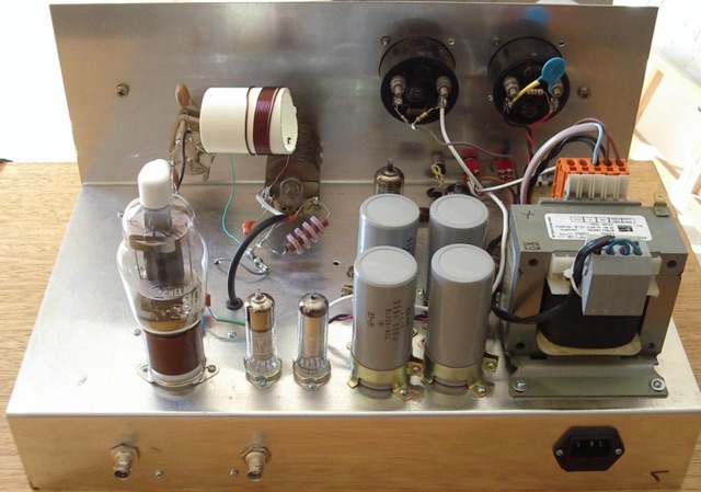 This page is a detailed description of a 6CL6 and 807 valve transmitter. The page includes the complete circuit diagram to build this transmitter and several pictures
 -
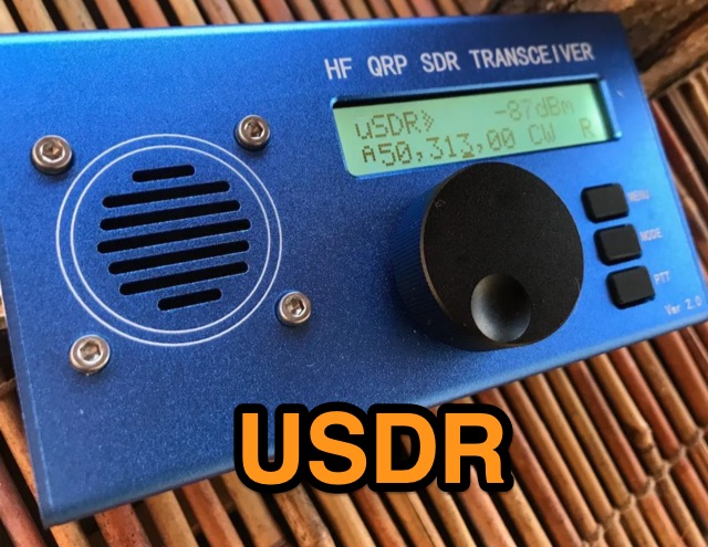 A review of the Chinese version of uSDX USDR HF QRP Transceiver. Author made an extensive review of receiver and transmitter features.
 -
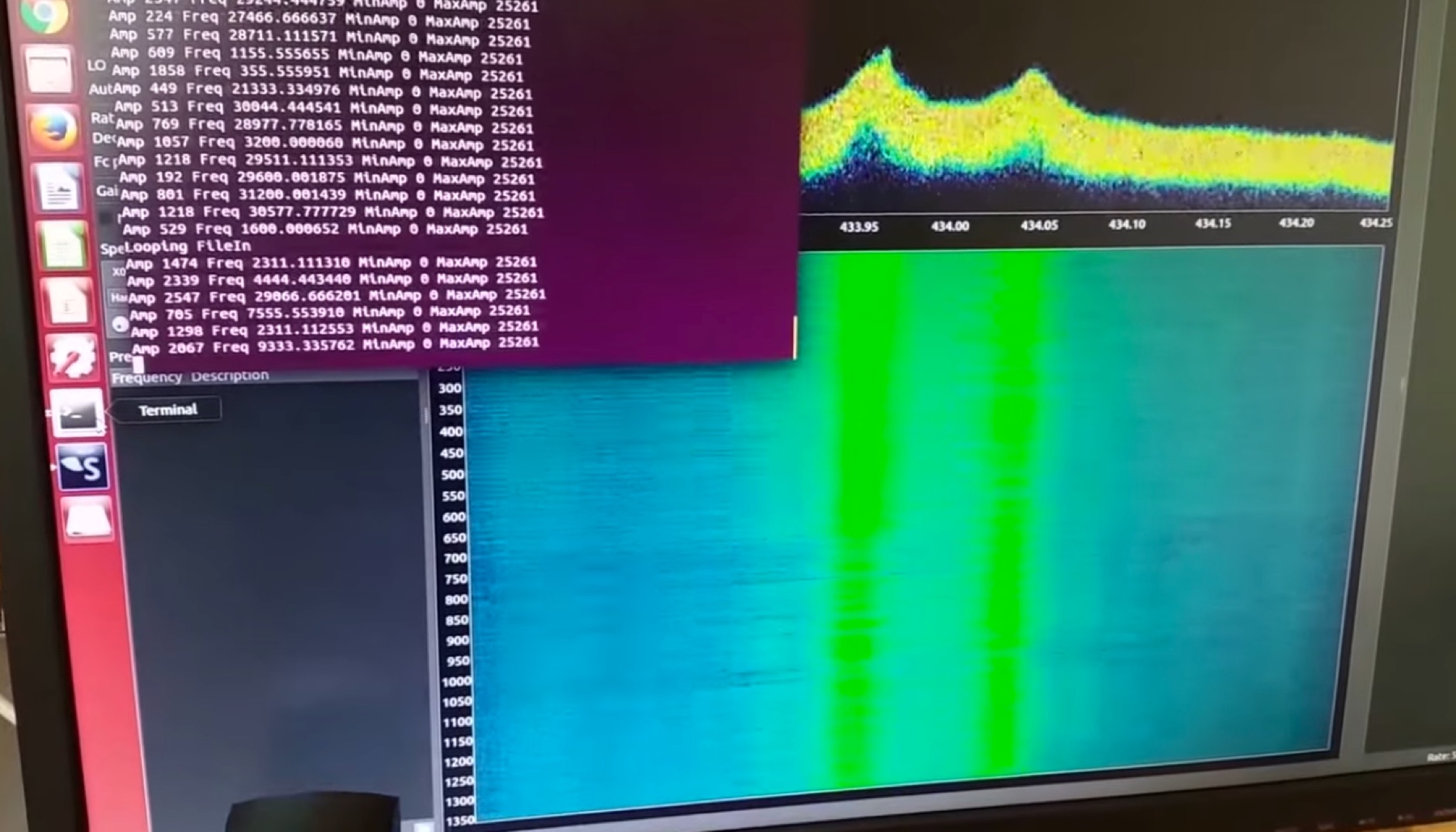 rpitx is a general radio frequency transmitter for Raspberry Pi which doesn't require any other hardware unless filter to avoid intererence. It can handle frequencies from 5 KHz up to 1500 MHz.
 -
 The North Shore Amateur Radio Club, Branch 29 of the New Zealand Association of Radio Transmitters (NZART) is an incorporated society for Radio Amateurs and interested persons.
 -
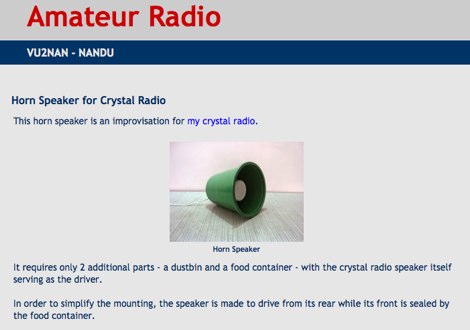 Homebrew Antennas, Transmitters, Receivers, Converters, Keyers and SWR/RF Current Indicators with photographs an excellent blog with many projects by VU2NAN
 -
 New Zealand Association of Radio Transmitters Auckland Branch 02
 -
 DF0WD/DL4YHF's Longwave Overview details amateur radio operations on the 135.7 to 137.8 kHz segment in Germany. The author outlines the "inofficial" European band plan, specifying segments for QRSS, TX tests, beacons, conventional CW, and data modes. Early LF activities at DF0WD began with a 20-watt CW transmitter, later upgraded to a homemade linear transverter capable of 100 watts, driven by an Icom IC706 on 10.137 MHz. The station's antenna system includes a 200-meter wire, approximately 10 meters above ground, supported by football field light-masts. Despite its length, the antenna's efficiency is noted as very low due to the immense wavelength of about 2.2 km. The author's experience highlights the significant challenge of achieving effective radiated power (EIRP) on LF, estimating DF0WD's EIRP at around 80 milliwatts based on field strength measurements from PA0SE. DF0WD/DL4YHF has successfully worked numerous countries on 136 kHz CW, including DL, F, G, GI, GM, GU, GW, HB9, HB0, LX, OE, OH, OK, OM, ON, OZ, PA, and SM. The author also mentions ongoing efforts to log contacts with CT, EI, LA/LG, and to complete a two-way QSO with Italy, demonstrating persistent activity on this challenging band.
 -
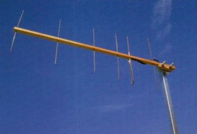 A collection of 450 MHz Cheap Yagis that have proven great portable operations, back-packing and transmitter hunts, and are something inexpensive you can throw up in the attic for that weak repeater
 -
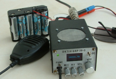 DK7IH QRP transceiver for 14 MHz. This small and compact home made transceiver with a max power output of 5W, the VFO module is based on the clock oscillator chip Si5351A by Silicon Labs ATmega168 and OLED 1306
 -
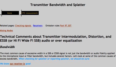 Technical Comments about Transmitter Intermodulation, Distortion, and ESSB (or Hi Fi Wide Fi SSB) audio or over equalization by W8JI
 -
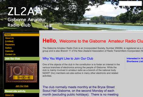 The Gisborne Amateur Radio Club is an Incorporated Society, Number 258284, is registered as a charitable group and is also Branch 11 of the New Zealand Association of Radio Transmitters Incorporated
 -
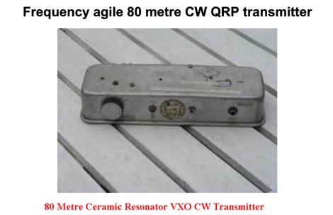 Frequency agile 80 metre CW QRP transmitter. Ceramic resonators vary in the frequency shift obtainable. The one in the prototype of this article gave 3.525 to 3.558 MHz coverage.
 -
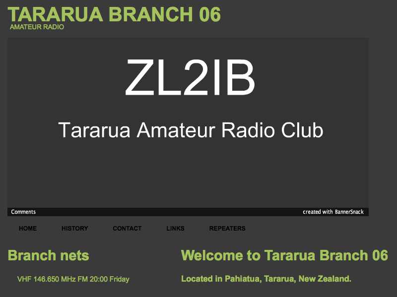 The Tararua Amateur Radio Club, Branch 06 of the New Zealand Association of Radio Transmitters (NZART) is an incorporated society for Radio Amateurs and interested persons.
 -
 Active RDF club in California
 -
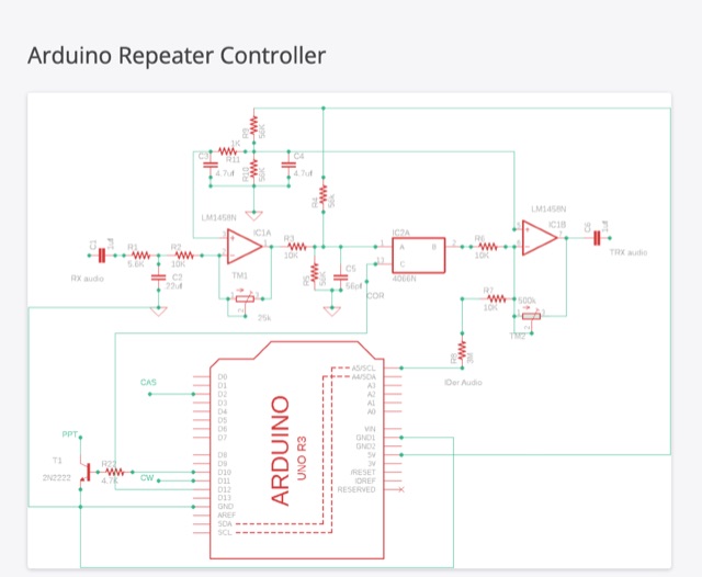 This blog article introduces an updated repeater controller project utilizing the Arduino UNO. It includes a CW identifier, and the ID message can be customized using hex codes. The author offers a Windows command line program for easier message coding and provides a link for download. The controller features three adjustable timers for IDer, Timer-out, and Squelch-tail. The article also mentions the use of an audio switch to control audio levels between the receiver and transmitter. Detailed instructions and code files are available on the author's website for both version 1 and version 2 of the Arduino repeater controller. The project aims to enhance repeater functionality and audio management in ham radio operations.
 -
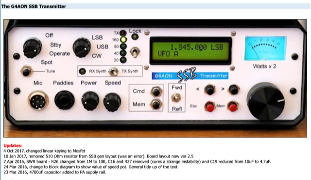 This transmitter covers the 160, 80, 40 and 20 metre bands and provides both SSB and properly generated CW. The CW side of this transmitter is not compromised and produces excellent CW. On SSB the audio has been tailored to provide a rising response to 3 KHz, with a sharp drop above that frequency. There is RF speech clipping to both provide more "punch" and to limit the peak output.