Search results
Query: 6 meters band
Links: 610 | Categories: 5
-
 A delta loop antenna for 17 meters band include eznec antenna model file
 -
 A vertical antenna for 40 and 80 meters band with no need of antenna tuner, based on a telescopic fiberglass mast of 48 feet by N8NSN
 -
 This resource details the computer-optimized design of the _ZS6BKW_ multiband dipole, an evolution of the classic _G5RV_ antenna. It begins by referencing the original 1958 RSGB Bulletin article by Louis Varney G5RV, explaining the operational principles of the G5RV's flat-top and open-wire feedline on 20m and 40m, noting its impedance transformation characteristics for valve amplifiers of that era. The article then transitions to the rationale for optimizing the design for contemporary solid-state transceivers requiring a 50 Ohm match. The core of the project involves using computer modeling to determine optimal lengths for the flat-top and matching section, aiming for a VSWR of less than 2:1 on multiple HF bands. It discusses the process of calculating feedpoint impedance based on antenna length and frequency, referencing professional literature from Professor R.W.P. King at Harvard University. The analysis also considers the characteristic impedance (Z(O)) of the open-wire line, identifying a broad peak of adequate values between 275 and 400 Ohms. Specific design parameters for the improved ZS6BKW are presented, including a shorter flat-top and a longer matching section compared to the original G5RV, with a velocity factor of 0.85 for the 300 Ohm tape. The article confirms acceptable matches on 7, 14, 18, 24, and 28 MHz bands when erected horizontally at 13m, and also discusses performance in an inverted-V configuration, noting frequency shifts. The author, Brian Austin ZS6BKW, emphasizes the antenna's suitability for modern 50 Ohm coaxial cable without a balun.
 -
 Presents the design and construction of the OK2FJ Bigatas, a portable, automatically tuned vertical antenna covering 80 through 10 meters. It details two distinct control systems: one utilizing BCD band data from Yaesu FT-857/897 transceivers, and another employing voltage level sensing for the Yaesu FT-817. The resource provides specific instructions for building the antenna's radiating element, loading coil with switchable taps, and the control circuitry, emphasizing the use of readily available components. The article outlines the physical construction of the antenna, including the use of duralumin tubes for the radiator and a PVC tube for the coil form. It specifies coil winding details, tap points, and the integration of radial wires for ground plane operation. The control electronics section provides schematics and component lists for both the BCD decoder (using a 74LS42 IC) and the voltage comparator (using an _LM3914_ bargraph driver), enabling rapid, automatic band switching without the minute-long tuning delays common in other systems. Crucially, the antenna achieves rapid band changes, with typical SWR values centered on common operating segments, such as **3.7 MHz** for 80m SSB. It also discusses modifications for CW operation on 80m and the trade-offs between antenna efficiency and full-range automatic tuning on higher HF bands, where manual adjustment of radiator length is suggested for optimal performance on 15m, 12m, and 10m. The resource includes construction photos and a discussion of cable requirements for reliable operation.
 -
 F6CHT plan for a multiband yagi antenna that covers 6 to 30 meters band in french
 -
 VHF Optimized Yagi Antenna for the 6-meter band (50 Mhz) by ON6MU
 -
 A vertical half-moxon for the 7 Mhz by F6IRF
 -
 A quarter wave vertical end-fed antenna for the 40 meters band. As all vertical antennas, also this aerial requires a good earthing system. In this project the ground is composed by twelve 4, wires buried in the lawn by using a spade to create a slit to drop the wire into.
 -
 A multiband antenna that can work from 80 to 10 meters in this illustrated docuemnt by G8ODE
 -
 A simple antenna that can be erected very fast, only need one center support, and do not take up much storage room. Works from 40 to 10 meters band
 -
 Presents a comprehensive guide for constructing a broadband Hex Beam antenna, a popular directional array for HF operation. This design offers a compact footprint and excellent gain characteristics, making it suitable for limited space installations while providing significant performance advantages over omnidirectional antennas. The resource details the specific dimensions for a five-band Hex Beam covering 20, 17, 15, 12, 10, and 6 meters, emphasizing the critical element spacing and wire lengths required for proper resonance and pattern. It outlines the construction of the center post, spreaders, and wire elements, along with the feed point assembly, ensuring proper impedance matching. The project aims for a forward gain of approximately **5.5 dBi** on most bands, with a front-to-back ratio often exceeding _20 dB_. Building this antenna requires careful measurement and assembly, but the resulting performance provides a substantial upgrade for DXing and contesting.
 -
 3 Band vertical Marconi-antenna for the bands 40, 80, 160 meters with a ground net of wires as radials.
 -
 A shortened dipole for 40 meters band by Martin E. Meserve
 -
 30/17/12 and 20/15/10-Meter Tribanders and a 40 meters inverted V wire yagi antenna
 -
 A Mini Moxon antenna for 40 meters band project in a well done PDF document
 -
 A monoband yagi for 14 MHz a PDF article from 73 amateur radio magazine by AB4GX
 -
 AB4GX K4EAA Mononband yagi antenna for 20 Meters
 -
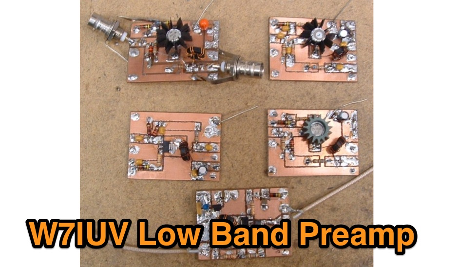 Pre amplifier using a 2N5109 for the 160 meters band
 -
 An easy to build single wire antenna for 160 and 80 meters with a better than 2 to 1 swr across the 80 meter band
 -
 Illustrates the specific wiring and configuration steps required to interface an SGC-230 Smartuner with an Icom IC-706 HF/VHF/UHF transceiver. The document details the necessary connections for power, control, and RF signal paths between the two devices, ensuring proper impedance matching and automatic antenna tuning functionality. It specifies the pin assignments for the IC-706's ACC socket and the SGC-230's control port, crucial for successful integration. Outlines the operational considerations for the combined system, including initial setup procedures and potential troubleshooting tips for common connectivity issues. The resource presents a clear, diagrammatic representation of the interconnections, which aids in visual comprehension of the required cable fabrication or modification. Covers the specific settings within the IC-706 menu that need adjustment to enable external tuner control, such as the 'TUNER' function and other relevant parameters. This ensures the transceiver correctly communicates with the SGC-230 for efficient antenna tuning across various amateur bands.
 -
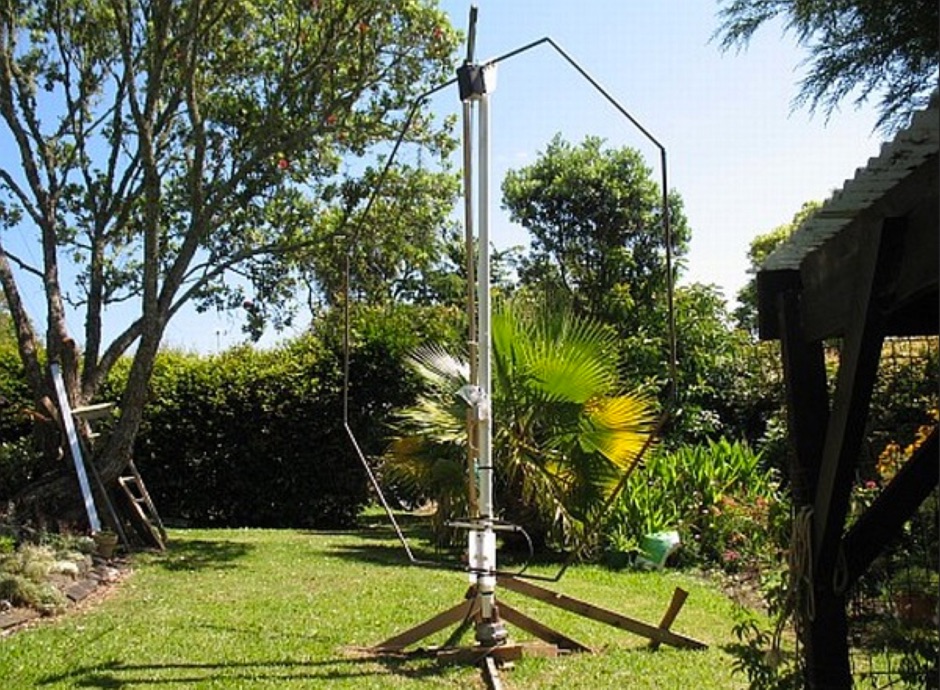
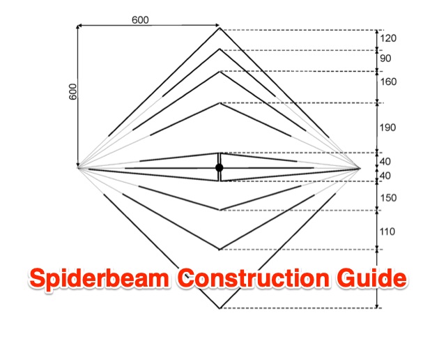 Build a spiderbeam from scratch for 20-17-15-12-10 meters band
 -
 A W3DZZ trapped dipole for 80 40 and 20 meters band by ZL1BJQ
 -
 This is a popular antenna design as the performance is very good across the HF bands and requires little or no tuning. It is a dipole fed off center with a 4:1 current balun at the offset feedpoint. The antenna shown covers 80, 40, 20 and 10 meters with 15 meters and WARC bands
 -
 A well documented article on a small magnetic loop antenna for the 40 meters band
 -
-
 The ZS6BKW wire antenna, a variant of the G5RV, utilizes a specific 13m (42.6 ft) length of 450-ohm window line as its matching section, feeding a 28.5m (93.5 ft) flat-top element. This design aims for lower SWR on 40m, 20m, 17m, 12m, and 10m compared to a standard G5RV, often achieving SWR values below 1.5:1 on these bands without an antenna tuner. The feedpoint impedance transformation provided by the window line allows for direct connection to 50-ohm coax on multiple bands. F4FHH's experience involved constructing the ZS6BKW and evaluating its performance against an _OCF dipole_ (Off-Center Fed) on various HF frequencies. The article includes observations on SWR readings and operational effectiveness, highlighting the ZS6BKW's suitability for multi-band operation. The antenna's overall length, including the flat-top and window line, is approximately **41.5 meters** (136 feet), making it a significant wire antenna for fixed station use. Comparative analysis with the OCF dipole provided practical insights into the ZS6BKW's advantages and limitations, particularly concerning bandwidth and tuner requirements.
 -
 An home made trapped dipole antenna for 40 and 60 meters band by 2E0HTS
 -

-
 A page about a Magnetic loop antenna project for the 40 meters band, includes nice pictures and history of construction
 -
-
-

-
 A telescopic pole that you adjust to suit the band you're working on , tested on 40 20 and 15 meters band by M0PZT
 -
 An 87ft inverted L portable antenna working on 80 40 30 20 15 meters band
 -
-
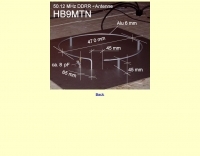 Pictures and dimensions of and HB9MTN DDRR antenna for 6 meters band
 -
 VU2VWN project to homebrew a CW for 40 meters band
 -
 A multiband wire antenna with a twinlead feedline that can be easily tuned in several bands, witha 33 ft per leg you can have a 40 to 10 meters band coverage
 -
 An homebrew crossed Yagi antenna for two meters band based on DK72B design with pictures, detailed description and tricks by Barry Zarucki M0DGQ
 -
 Operating a ZS6BKW antenna often involves understanding its lineage from the _G5RV_ design, with specific modifications by ZS6BKW to optimize performance on several bands. Through computational analysis and field measurements, the antenna's dimensions were refined to allow operation on 10, 12, 17, 20, and 40 meters without an antenna tuner. For 80, 30, and 15 meters, a tuner is necessary, though efficiency on 30 and 15 meters is noted as not particularly high. The physical configuration consists of two 13.755-meter radiating elements fed by a 12.20-meter section of 450-ohm ladder line. Tuning the antenna on the 20-meter band is critical, and any deviation in the ladder line's characteristic impedance necessitates recalculating the element lengths. The design is also referenced in the 12th edition of _Rothammel's Antennenbuch_, page 219. Proper common mode current suppression is crucial at the transition from ladder line to coaxial cable. This can be achieved with a common mode choke, such as several turns of coax wound into a coil or over a ferrite toroid like an Amidon T130. While a 1:1 balun is an option, it may introduce issues.
 -
 A 90-foot vertical antenna constructed from **aluminum irrigation tubing** is detailed, focusing on its innovative raising and lowering mechanism. The resource describes a **45-foot ginpole** system, allowing a single operator to erect or lower the antenna in minutes. It covers the mechanical design, including the pivot base, insulated joints for the tubing sections, and guy wire attachment points. The antenna consists of two 30-foot sections of 4-inch tubing and one 30-foot section of 2-inch tubing, stacked with the smaller diameter at the top. The electrical design incorporates PVC "condulet" boxes at the 30-foot and 60-foot points, housing relays to change the effective height for multi-band operation on 160, 80, 40, and 30 meters. Ferrite rod inductive chokes are used for DC control and to tune out gap capacitance. The antenna is fed with 1000 feet of open wire line, connected to a matching transformer comprising stacked toroids and a coaxial/toroidal balun. Grounding is achieved with a 3x3 foot grid of 16-gauge tinned copper wires with soldered crossovers.
 -
 Alfa Tango DX is a premier resource for operators on the 11 meters band, providing a searchable database that includes news, cluster information, and discussion boards. This platform serves as a hub for DXers and contesters, offering valuable insights into activations, dx-peditions, contests, and meetings worldwide. The site features a variety of resources, including event calendars, award programs, and tools for logging contacts. Members can access exclusive content and participate in contests like the AT Women's Day Contest and the Eleven World Wide Contest. With a focus on community engagement, Alfa Tango DX fosters connections among operators and promotes the spirit of amateur radio. Whether you are a seasoned DXer or a newcomer to the 11m band, Alfa Tango DX provides essential information and support for enhancing your amateur radio experience. From QSL services to event participation, this resource is designed to meet the needs of all operators interested in the 11 meters band.
 -
 Operational testing of a 10.07-meter portable HF vertical antenna, constructed from telescoping aluminum tubing (36, 32, 22, 17 mm diameters), yielded SWR measurements below 1.5 across multiple bands. Initial trials on 14.150 MHz showed an SWR of 1.6, while 7.075 MHz was problematic. Subsequent adjustments, including a 13 cm extension to the radiating element, improved performance, enabling operation on 6, 15, and 40 meters without a balun, and adding 12 meters with a balun. The design prioritizes portability, allowing transport in a standard vehicle and single-person deployment. Four 10.07-meter radials are connected at the base to enhance ground plane effectiveness. The article details the mechanical assembly, including custom adapters for tube transitions and a PVC sanitary tube sleeve for base insulation, ensuring robust field deployment. Final SWR measurements, documented with an _MFJ-259_ antenna analyzer, confirm operational ranges: 6.800-7.500 MHz (SWR < 1.5), 20.800-22.500 MHz (SWR < 1.5), and 48.800-51.500 MHz (SWR < 1.5) without a balun. With a balun, the antenna achieved SWR < 1.5 on 13.750-15.000 MHz and 24.890-28.350 MHz, demonstrating its versatility for portable _DXpeditions_.
 -
 A copper pipe Hentenna for 144 MHz. The Hentenna, a compact, high-gain loop antenna developed in Japan in the 1970s, offers approximately 5.1 dBd gain, comparable to a three-element Yagi. Adapted for 2 meters, it is crafted from copper pipe for simplicity, affordability, and broadband performance. Requiring no feed-point tuning, its construction involves soldering standard copper fittings. Installation demands non-conductive materials to minimize signal disruption. Versatile for vertical or horizontal polarization, it is ideal for FM, repeater, SSB, or CW applications. This design emphasizes practicality and performance for amateur radio enthusiasts
 -
 This antenna consists of 4 resonate dipoles made from 12 insulated copper electrical wire. The dipoles are resonate on the following bands: 6 meters, 10 meters, 12 meters and 17 meters.
 -
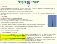
 A delta loop antenna for 6 meters band with SWR diagram , construction plan and some pictures by IZ8EWD in Italian
 -
-
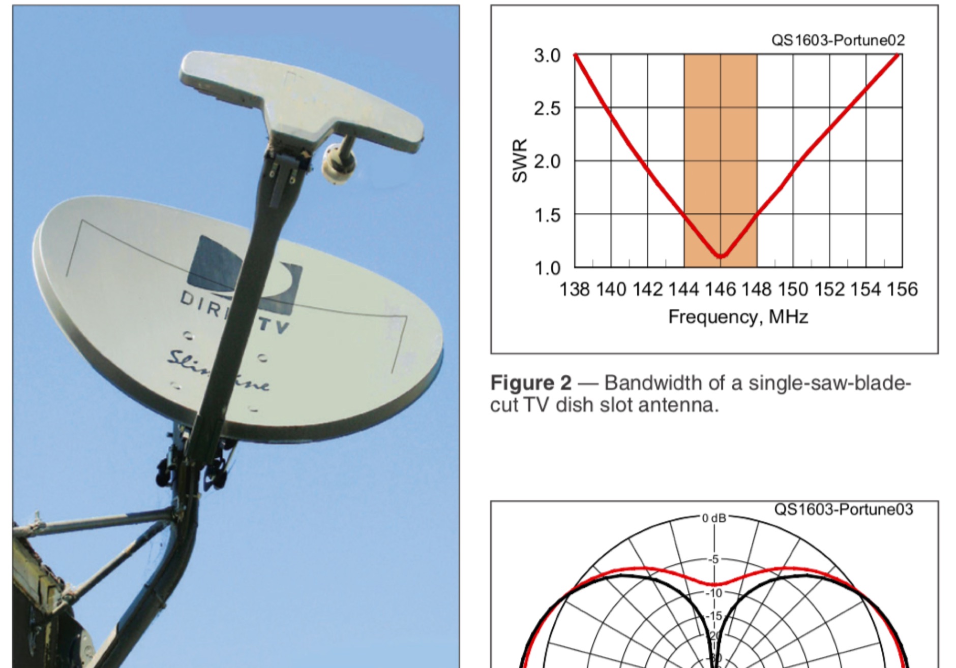 An efficient 2 meter antenna disguised as a TV Satellite dish. This vertically polarized horizontal slot antenna, cut into the reflector of a TV dish, might be the ultimate stealth antenna.
 -
 G3WZT John Matthews project of a 600 Watt solid state linear amplifier for the 6 meters band
 -
 Demonstrates the design and construction of a 9-element Yagi antenna for the **70 cm band** (432 MHz), based on the DK7ZB concept. The resource details EZNEC+ calculations for a single antenna, providing gain, sidelobe suppression, and front-to-back ratio figures. It also presents a comprehensive analysis of stacking two such antennas, including optimal stacking distance (1000 mm) and the resulting performance enhancements for the stacked array, such as an increased gain of 17.03 dBi. The article includes detailed drawings, wire file dimensions in millimeters, and azimuth/elevation plots for both single and stacked configurations. Practical construction steps are documented with original photographs, illustrating element mounting, the **28 Ohm matching system** using two quarter-wave 75 Ohm transmission lines, and the critical N-connector wiring. It also covers the iterative process of fine-tuning the driven element length to achieve a return loss of 20 dB, validating the EZNEC+ simulation results with actual measurements.