Search results
Query: feed line
Links: 236 | Categories: 4
-
 The 1/4 wavelength vertical antenna project, initially designed for 20 meters, has evolved into a versatile portable solution covering 10 through 60 meters. K0BXB details its construction, emphasizing a bottom-loaded design with a tapped loading coil and four 10-foot counterpoise wires. The author shares personal experiences and field results, including **18 QSOs** during a park activation on 17m and 30m with 10 watts, and a **2,435-mile** contact with a contest station in Bonaire on 20m using 5 watts. Comparisons are drawn to commercial offerings like the _Wolf River Coils TIA_ and _QRPGuys Triband Vertical_, highlighting the DIY antenna's small footprint, light weight, and ease of tuning for POTA activations. The resource includes insights into using test equipment such as the _NanoVNA_ for SWR optimization and discusses various radiator lengths, from 17-foot wire to a 102-inch whip, demonstrating adaptability for different portable setups. Construction tips cover coil winding, tap placement, and connecting feedlines and radials using common components.
 -
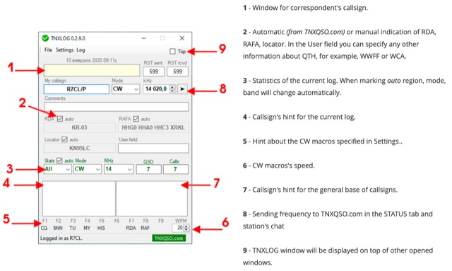 TNXLOG is a specialized logging application designed to complement the TNXQSO.com online service, focusing on real-time data exchange rather than serving as a standalone general-purpose logbook. The software facilitates the transmission of current **QSOs** to the TNXQSO.com server and simultaneously retrieves relevant geographical data such as RDA, Locator, and RAFA from the same server. It maintains real-time QSO statistics, providing operators with immediate feedback on their activity. Additionally, the application supports working with **CW macros** via a COM port, streamlining Morse code operations during contacts. This utility is specifically tailored for users of the TNXQSO.com service, enhancing their operational experience by automating data synchronization and providing instant access to location-specific information. Its design prioritizes integration with the online platform, making it a companion tool for those engaged in specific award programs or regional operating activities that benefit from real-time data exchange and statistics. The software's functionality is distinct from traditional logbook programs, emphasizing its role in a connected operating environment.
 -
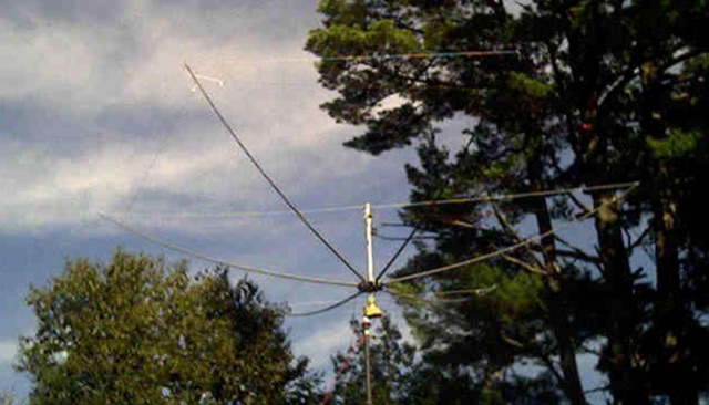 The Hex Beam page by W1GQL page, a document dedicated to home brewing hex beam antenna with dimensions, info on spreaders, wires to use, spacing tips, feed line information, mast to use, multi-band version and antenna height
 -
 The multiband tuned doublet, or center-fed Zepp, is a simple and efficient HF antenna that operates effectively across most amateur bands using a balanced parallel-wire feedline and antenna tuner. Unlike coax-fed dipoles, it tolerates impedance mismatches with minimal loss. By selecting suitable feedline and dipole lengths, one can achieve stable multi-band operation. While it doesn’t match monoband Yagis, it offers excellent performance, low cost, and broad coverage. Its radiation pattern and efficiency vary with frequency, but it remains a practical and versatile solution for HF operators.
 -
 The article describes the construction of a Lindenblad antenna, which is well-suited for receiving signals from low-orbiting weather satellites. The key points are: The Lindenblad antenna has an omnidirectional horizontal radiation pattern and is optimized for low to medium elevation angles, making it ideal for tracking passing satellites near the horizon. It is designed to receive circular polarization, which is common for weather satellite signals. The antenna is constructed using 4 folded dipole elements arranged on a cross-shaped frame. The necessary materials include a plastic junction box, PVC tubing, and aluminum rods to form the dipole elements. The article provides detailed instructions for preparing the components, assembling the dipoles, and connecting the feed lines to create the complete antenna. The completed antenna can be mounted on a vertical support, with the dipole elements angled at 30 degrees from horizontal, to optimize reception of the passing satellites. The author notes that the design was originally published in a now-defunct magazine, Meteo Satellite Inf", in 1993
 -
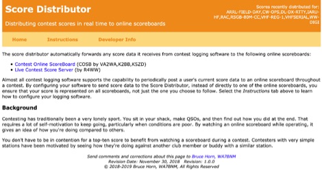 The Score Distributor facilitates real-time score forwarding for amateur radio contests, automatically transmitting data from various logging software to multiple online scoreboards. By configuring logging applications to send score data to the Distributor, operators ensure their current score is simultaneously represented on platforms like the _Contest Online ScoreBoard_ (COSB) and the Live Contest Score Server by R4WW. This system eliminates the need to choose a single scoreboard, providing broader visibility for participants. This utility enhances the competitive experience by allowing contesters to monitor their performance against other stations throughout an event. Observing real-time standings can provide significant motivation, particularly during periods of challenging propagation or when striving to maintain pace with club members or peers. The platform supports almost all major contest logging software, simplifying integration for a wide range of operators. Developed by WA7BNM, the Score Distributor was last revised on June 14, 2023. It aggregates score data, offering a unified point of submission that then disseminates the information, ensuring a **single point of entry** for broad scoreboard coverage and improving the dynamic feedback loop for participants.
 -
 Constructing a double bazooka antenna for the UHF band, specifically tuned for 435 MHz, involves a straightforward process detailed with step-by-step imagery. The design leverages readily available _RG213 coaxial cable_, cut to precise lengths derived from formulas: 140.208 / F (MHz) for the radiating element and 99.06 / F (MHz) for the coaxial section. This approach yields a highly effective vertical polarization antenna, suitable for local ragchewing or repeater access. My own field experience with similar coaxial designs confirms their robustness and ease of deployment. The article emphasizes critical steps like short-circuiting cable extremities, interrupting the braid at the center, and securing an insulating support. It also covers preparing the definitive mounting with a quality feedline, noting that RG58 is acceptable for temporary use but better options exist for permanent installations. Weatherproofing is crucial for longevity, achieved through PVC electrician's tube, glue, and heat-shrink tubing. The final assembly is designed for mounting on a small aluminum mast, with the feedline routed internally. The reported SWR measurement is very satisfactory, showing approximately **+/- 3%** HF return, indicating excellent impedance matching at the target frequency.
 -
 The All-Copper J-Pole Antenna Construction for 2 Meters document outlines a specific build methodology for a VHF base station antenna. It addresses common issues like dissimilar metal corrosion and feed line degradation often encountered with aluminum J-Pole designs, proposing an all-copper and brass solution with soldered connections for enhanced durability and electrical performance. This resource provides a comprehensive parts list in Table 1, detailing precise copper tubing lengths and other necessary hardware components. The design emphasizes DC grounding, which eliminates the need for insulating materials and simplifies installation, contributing to a robust and weather-resistant structure. Michael P. Hood, KD8JB, details an assembly process estimated to take approximately one hour, with total material costs projected under $15. The antenna's construction focuses on rigid copper tubing and fittings, ensuring long-term integrity for 144 MHz operation.
 -
 Addresses the common challenge of constructing effective dual-band antennas for VHF/UHF operations, specifically detailing a J-pole design. It covers the theoretical underpinnings, including calculations for quarter-wavelength radiator and stub sections, accounting for velocity factor and design frequency. The resource provides practical construction guidance using readily available materials like TV twin lead and coaxial cable, culminating in an antenna with a total length of approximately 52 inches. Performance metrics are presented, showing a measured SWR of 1.7:1 or better across most of the 2-meter band and less than 2:1 across the 70-cm band. These SWR measurements, referenced to 50-ohm impedance, were taken at the transmitter end of the feed line. The article also touches upon the necessity of a balun for proper impedance matching between the balanced J-pole and unbalanced coaxial feed line, suggesting a split-core cylindrical ferrite for this purpose.
 -
 This comprehensive three-part guide examines baluns (balanced-to-unbalanced devices) and their critical role in ham radio antenna systems. The author explains how baluns prevent common-mode currents on feedlines, which can distort radiation patterns and cause unwanted RF in the shack. Various balun types are analyzed, including coiled coax chokes, ferrite-core designs (W2DU), and toroidal-wound versions (Guanella/Ruthroff). Construction techniques for 1:1, 4:1, 6:1, and 9:1 current baluns are provided with practical guidance on wire selection, winding methods, and ferrite core properties. The article emphasizes that proper balun implementation is essential for optimal antenna performance, especially with directional arrays.
 -
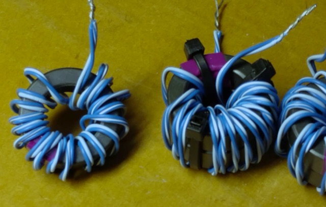 Chokes and isolation transformers are essential for receiving antennas to mitigate common mode current, which induces noise and interferes with signal quality. Common mode chokes, formed by winding feedline through ferrite cores, block unwanted current effectively. Proper selection of core material and winding turns ensures resonance near the operating frequency, reducing interference. Isolation transformers further minimize interference, crucial for multi-transmitter stations.
 -
 The tri-band trapped delta loop antenna design operates on 80 meters (3.5–4 MHz), 40 meters (7–7.3 MHz), and 30 meters (10.1–10.15 MHz) using a single triangular wire loop. This configuration eliminates the need for an external antenna tuner or band-switching relays. The antenna's physical perimeter, approximately 270 feet, establishes 80M as the fundamental band, with specific trap placements enabling resonance on 40M and 30M. Trap design and placement are critical, with 30M traps positioned inboard of 40M traps within the horizontal element. Each slant leg measures approximately 80 feet. The resource references foundational information from the _ARRL Antenna Handbook_ and _ON4UN’s Low Band DXing_ regarding full-wave loop behavior and feedpoint impedances. The project aims to provide multi-band HF operation from a single, fixed antenna structure.
 -
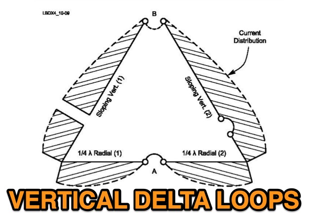 A vertical delta loop is a practical antenna for low bands, popular for its simple design requiring just one support. Its shape, an equilateral triangle in free space, yields optimal gain and radiation resistance. Deviating from this shape lowers performance. The delta loop can be polarized either horizontally or vertically based on the feed point location. In vertical polarization, it acts as two quarter-wave verticals with the baseline feeding one side. This design minimizes radiation from the baseline while maintaining effective operation.
 -
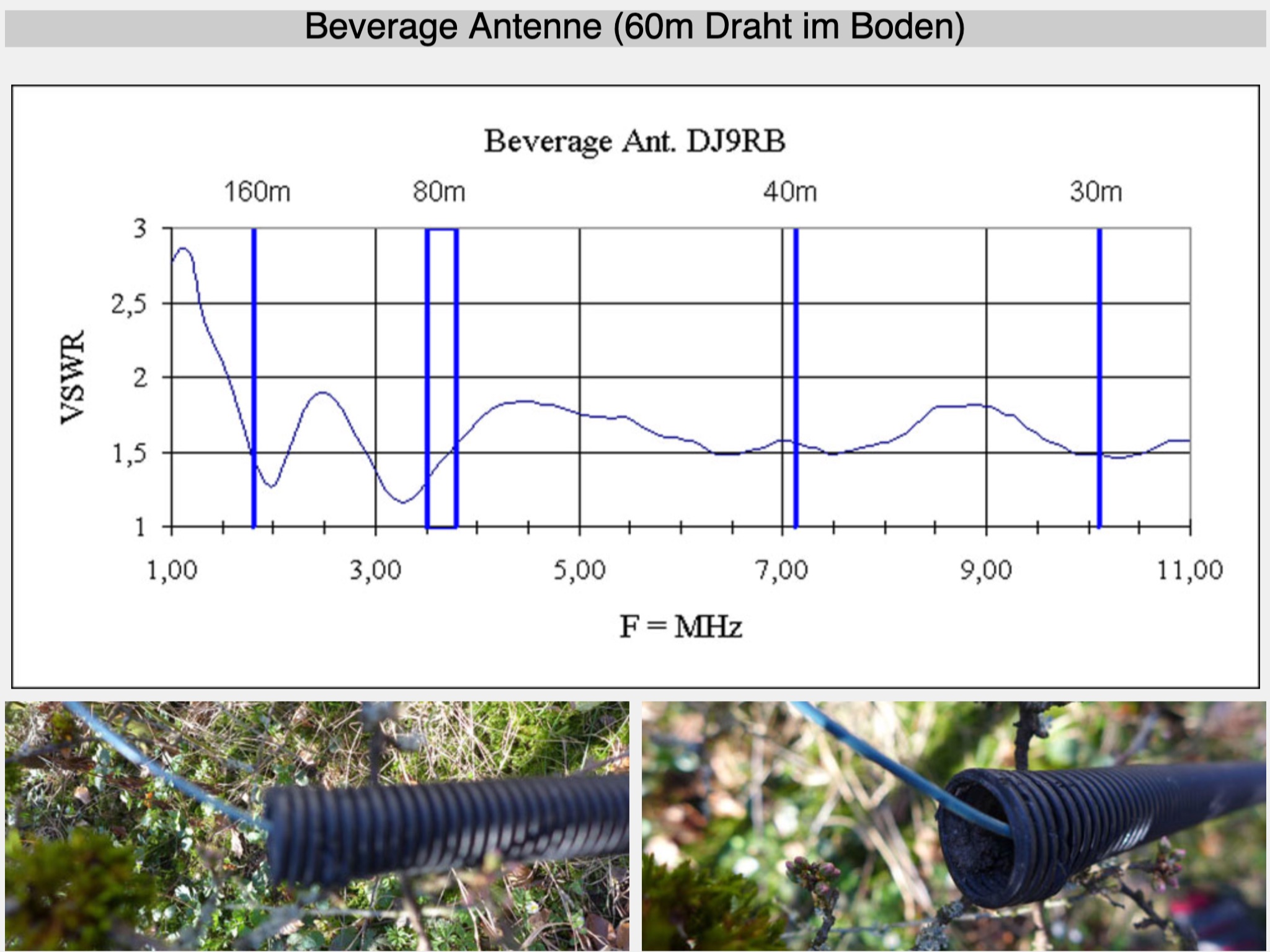 This page provides information about building a Beverage antenna for hams. The article discusses using a 60m wire on the ground to create an effective antenna for amateur radio operators. Learn how to set up and optimize this type of antenna for better reception and communication. This describes a low-noise receiving Beverage antenna setup for low bands, using a N30 cup core transformer for 1:4 impedance matching (likely 50:200 Ohm), RG-58 feedline with heavy common-mode choking, and conduit for wire burial.
 -
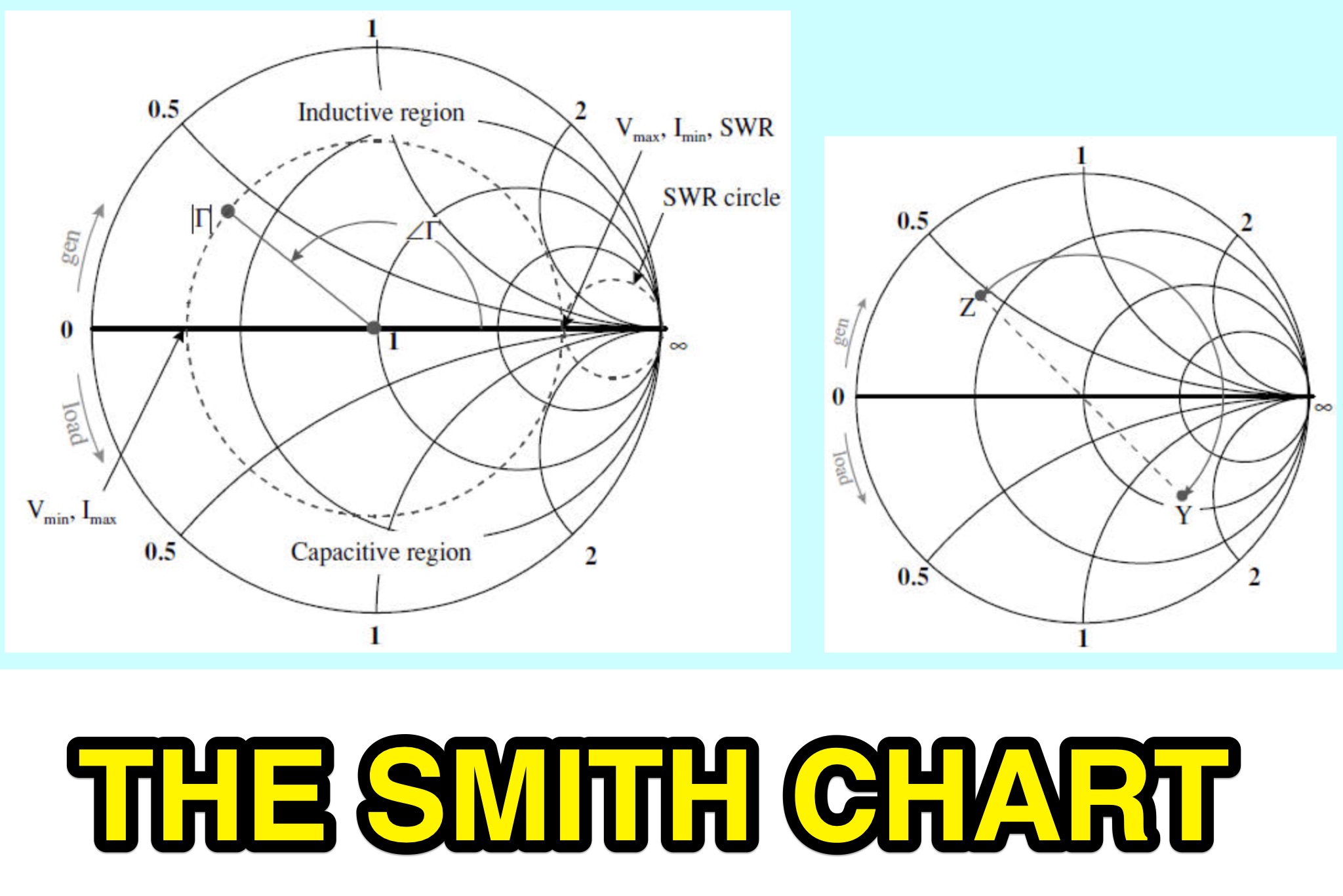 The Smith Chart, named after its inventor Phillip H. Smith, is a graphic tool used to solve transmission line problems in the field of ham radio operations. By using the Smith Chart, ham radio operators can determine the feed point impedance of an antenna, design impedance-matching networks, and optimize power transfer between a source and its load. The chart consists of resistance and reactance circles, providing a visual representation of complex mathematical relationships related to transmission line operations. Understanding and utilizing the Smith Chart is essential for hams looking to enhance the performance of their RF circuitry.
 -
 Details the construction of a Copper Cactus Dual-Band Super J-Pole Antenna, providing specific measurements for 1/2-inch copper tubing sections, including a 57-1/2-inch long section and a 19-inch short section, along with a 42-inch piece of 3/16-inch or 1/4-inch soft copper tubing for the matching stub. It covers soldering techniques for copper fittings, drilling an SO-239 panel mount coaxial fitting, and securing feed point connections with stainless steel adjustable band clamps. The resource specifies materials such as Schedule M 1/2-inch copper tubing, various copper fittings, a hardwood dowel or Fiberglas rod for insulation, and #14 stranded copper wire for the feed point. The guide simplifies the J-pole feed point by using an SO-239 fitting with an elongated mounting hole and band clamps, noting an optimal feed point distance of approximately 3 inches above the crossbar for proper impedance matching. It recommends a 4-turn coax choke, 5 inches in diameter, placed within 3 to 4 inches of the feed point for 2-meter operation to mitigate RF on the feedline. The project emphasizes weather sealing with silicon or butyl rubber compound and clear lacquer for durability and appearance.
 -
 Fifty-one MHz operation, often called the "magic band," benefits significantly from a well-designed antenna, and this resource details the construction of a rigid 6-meter _Moxon antenna_ using common DIY store materials. The author, 4L/G8BAG, shares his experience with the 6m band, highlighting its potential for long-distance contacts, with single-hop sporadic E propagation enabling QSOs up to **2,500 km** and multi-hop contacts reaching **10,000 km**. The project emphasizes cost-effectiveness and durability, utilizing yellow gas pipe with an internal stainless steel lining for the antenna elements. The article provides specific dimensions for the Moxon rectangle, derived from the 12mm internal diameter of the gas pipe's steel core, rather than the outer plastic. It also details the use of white PVC water pipe for insulators and mounting, ensuring a tight fit with the yellow gas pipe. Initial testing with an MFJ antenna analyzer showed an excellent 1:1 SWR across the 50-52 MHz range, even when using 75 Ohm satellite cable as a feeder. The construction process is straightforward, involving cutting and bending the gas pipe, fitting insulators, and connecting the feedline. The author's successful on-air results, including a 1000 km contact with a temporary vertical, underscore the effectiveness of the 6m band and the Moxon design. The resource concludes with a note on exploring heavier gauge gas pipe for future 10m antenna projects.
 -
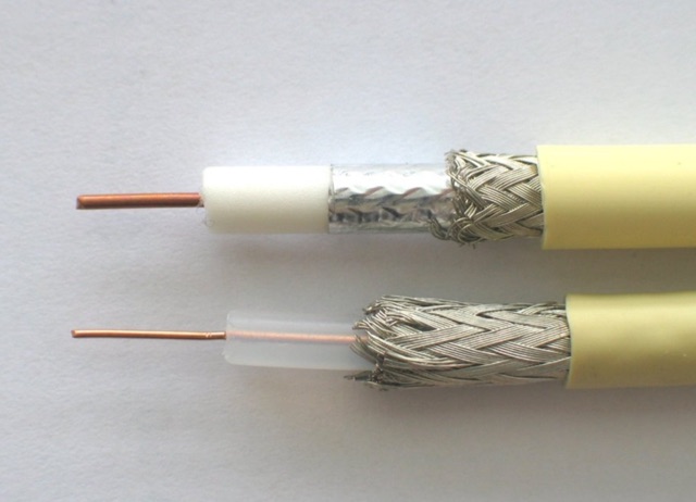 The feed line (also called the transmission line) is the RF power conduit between your radio and your antenna. The quality of your feed line is critical to your station. ARRL Article that explains differences among various commonly used feed line systems
 -
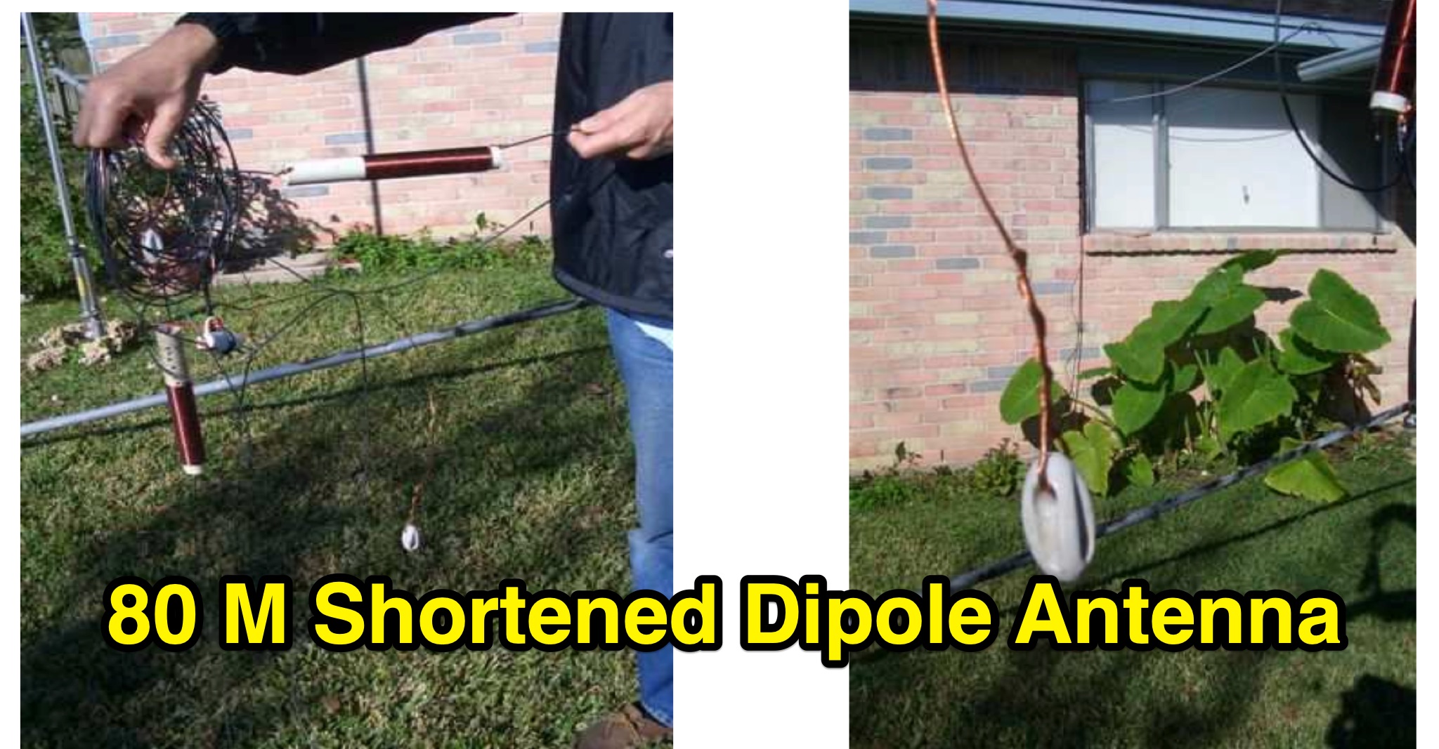 The LKJ Wednesday Night Special Antenna, designed by John Whiteman K5LKJ, is a compact 50-foot coil-loaded dipole for 80-meter operation, ideal for space-limited hams in residential areas. Using two 1-inch diameter PVC coils with 87 turns of #16 magnet wire each—placed 10 feet from the center—it tunes to 3.910 MHz for local nets like BVARC Rag Chew. Constructed with #14 wire, ceramic insulators, and Mini-8X feedline, it handles 1000W, performs well at low heights for NVIS, and requires a tuner for bandwidth. Collaborative tuning by club members ensured success.
 -
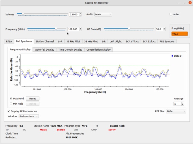 This document outlines various miniature projects undertaken by Mike Markowski to enhance his skills in GNU Radio. Key projects include an FM stereo receiver and an AM radio receiver, featuring advanced functionalities like pilot tone recovery and RDS integration. Additional experiments involve generating Gaussian noise, chirp signals, and Morse code decoding, emphasizing hands-on learning and customization in GNU Radio. The author encourages feedback and shares flow graphs and Python code for each project, aiming to foster community engagement and knowledge sharing.
 -
 Twigger is a very lightweight, free ham radio logger designed for Windows, offering seamless integration with transceivers via _TCI_ or OmniRig. This software stores all logged contacts in a SQLite database, with the flexibility to export daily ADIF files for import into a main logger or to send real-time QSO data via UDP in N1MM XML format. It also supports direct, real-time uploads to popular online logbooks like Clublog and QRZ.com, streamlining the logging process for active operators. The application has seen continuous development, with version 1.1.34 fixing an ADIF log importer bug and earlier versions adding crucial features like WSJT-X/JTDX UDP support. Author OE3IDE, Ernst, has incorporated user feedback, including ideas and testing from MW0LGE, to refine the software. Key enhancements include the transition to SQLite for data storage in version 1.1.32, allowing for easy import of previous Twigger ADIFs upon initial startup. The logger also features integrated DX cluster support, enabling users to send spots directly and query QRZ.com for callsign information, which is then cached to reduce redundant queries. The software's compact design and essential logging capabilities make it a practical tool for casual logging or as a secondary logger during contests, with the ability to handle **25 downloads** for version 1.1.34.
 -
 Details the installation and operation of the DX Engineering TFS Series Transmit Four Square System Phasing Units, specifically models like the DXE-TFS4-160B, DXE-TFS4-80B, and DXE-TFS4-40B. It covers system components, required parts, and a discussion of vertical antenna selection, including a table of suitable DX Engineering Monoband Vertical Antennas. Installation procedures are outlined, encompassing site selection, four square layout, topographical considerations, and noise source mitigation. Specific instructions are provided for mounting the phasing unit, antenna feedline connections using 1/4-wave 75-ohm coaxial cables, and control wire routing. The document also includes details on radial system implementation, with a table of radial wire lengths for 160, 80, 75, and 40 meters, and procedures for tuning the vertical antennas for optimal performance. Operational aspects of the Four Square Control Console are described, including front and rear panel functions, control logic (Table 4), and typical transceiver/amplifier interconnections. The system enables directional control with approximately 5 dB gain over a single vertical element in four directions or an omni-directional pattern, achieving typical front-to-back ratios exceeding 20 dB. Lightning protection and initial system testing are also addressed, along with a 5 kW CW and 10 kW PEP SSB power rating and hot switching lockout feature.
 -
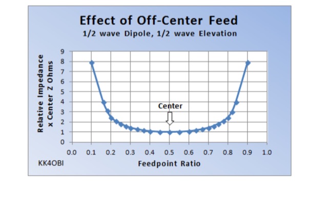 The behavior of a straight dipole and its L-form is examined in terms of impedance and SWR. By adjusting the feed point or bending angle, impedance variation is observed. Impedance shifts symmetrically as the feed point deviates, leading to recommendations for optimal ratios. Model simulations aid in understanding and fine-tuning, crucial for achieving a 50 Ohm match. Practical tuning guidelines ensure efficient antenna performance.
 -
 145 MHz is the target frequency for this 2-meter Skeleton Slot Yagi Stack antenna project. The design focuses on feeding two stacked Yagi antennas using a skeleton slot radiator, which is a unique approach for VHF enthusiasts. The project details the construction process, including the loop tapered matching section for impedance matching, ensuring optimal performance. The use of specific components like the EH789 element holder and MB456 main mast bracket is highlighted, providing clarity on the assembly process. The construction utilizes 20x20 box aluminum bar for durability and precision. Key dimensions, such as the element length (ER-ED4) and main boom spacing (MM123), are meticulously outlined. This attention to detail aids in replicating the antenna design accurately. The downloadable PDF offers comprehensive instructions, making it accessible for amateur radio operators interested in VHF antenna construction. This project is particularly beneficial for those looking to optimize their 2-meter band operations. The inclusion of a skeleton slot radiator and loop tapered matching section demonstrates advanced techniques in antenna design, catering to both intermediate and advanced builders.
 -
 This article demonstrates how to convert an existing tower into a dual-band vertical antenna for 80- and 160-meter DX operation. Using EZNEC modeling and practical design principles, the authors achieved a low-profile, efficient setup with a single coax feed line, no moving parts, and optimal radiation patterns. The system integrates an 80-meter vertical wire and a 160-meter shunt-fed gamma match for simultaneous operation. Detailed construction insights, including feed system and capacitor configurations, offer a reliable, full-legal-power solution.
 -
 Designing a collapsible 6-meter beam antenna involves careful consideration of element geometry and feedline matching, as demonstrated by VE3SMA's project. The construction draws inspiration from foldable dipole concepts and established wire beam designs like the Penn. State 40m beam and the DJ4SA Spiderbeam. Utilizing **4NEC2 modeling**, the author optimized element lengths for gain and bandwidth, observing the impact of end loops on resonant frequency and the need for compensation. Feeding the approximately 25-ohm balanced antenna with 50-ohm unbalanced cable required a specialized network. This setup incorporates a choke **balun** and a matching section built from two series quarter-wave transformers using readily available 75-ohm cable. On-the-air results validate the design, including a successful 1st double hop Es QSO with 10 Watts and satisfactory performance in the CW WW VHF Contest from FN05, where 41 grids were worked with 100 Watts, showing improved performance over a simple dipole.
 -
 This excel workbook addresses the issue of power loss in transmission lines with complex characteristic impedance ZoZo​. It illustrates the discrepancy between actual loss (0.35 dB) and matched line loss (0.6 dB) using a simplified example, highlighting potential software tool limitations. The RF Feedline Power-Loss Calculator provides accurate end-to-end loss assessments for both microwave and RF applications. This tool is suitable for engineers and students and is compatible with Windows versions of Excel 2016 or later, though it is not compatible with Macintosh systems.
 -
 Demonstrates a specific impedance matching technique for resistive loads ranging from 22.2 to 45 ohms, connecting them to a 50-ohm transmission line. The method employs series sections of 50-ohm and 75-ohm coaxial cables, with graphical data illustrating the required cable lengths (L1 and L2) in wavelengths for a perfect match. This approach is particularly useful for feeding **vertical** and **Yagi antennas**. The resource provides a practical example of matching a 25-ohm Yagi antenna at 50.150 MHz, specifying the use of RG-58C/U (50 ohms) and RG-59B/U (75 ohms) cables, both with a 66% velocity factor. It calculates the precise physical lengths in centimeters and inches for the required cable sections. Additionally, the document briefly discusses integrating a balun at the load end, suggesting methods such as coiling a cable section or utilizing ferrite beads to create a W2DU-type balun. The presented methodology offers a clear, data-driven solution for common antenna impedance challenges.
 -
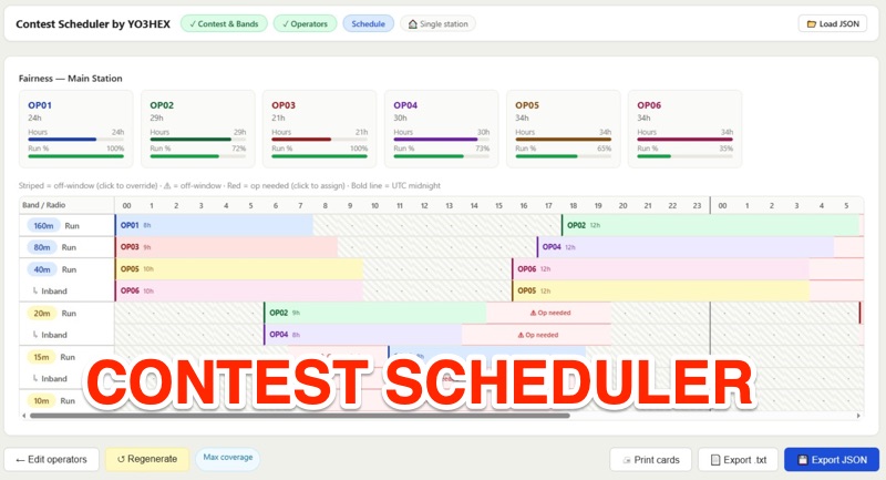 This online tool is a specialized web-based utility for orchestrating multi-operator HF contest and DXpedition activities. This tool, _Rig2Cast_, assists station managers in meticulously planning operator shifts, ensuring adequate rest periods, and crucially, preventing operational conflicts such as assigning a single operator to multiple radios concurrently. It integrates support for SO2R operations and offers real-time simulation of operator requirements, a feature I've found invaluable in pre-event planning. The scheduling engine incorporates five distinct algorithms: greedy fairness balancing, round robin, maximum coverage, simulated annealing, and a fatigue-aware model. These algorithms enforce critical constraints like minimum/maximum shift durations and mandatory rest times across all radios, which directly impacts operator performance over long events. My field experience confirms that such robust constraint management is essential for maintaining peak efficiency during intense operations. Key features include distributed multi-station support, printable per-operator cards, flexible band activity windows, and real-time editable operator slots. The drag-and-drop shift management, coupled with full cross-radio swap support and smart constraint feedback (valid targets in green, invalid in red), streamlines complex scheduling tasks. The system's design ensures user data privacy, as no information is stored on the server; schedules are saved and reloaded locally.
 -
 AA9PW offers free practice exams for all three US license classes plus international licenses like Canadian and Australian. The site generates random tests from the current question pools, simulating the actual exam experience. You can choose between online exams or printable PDF versions for offline study. The site maintains a simple, no-frills interface that loads quickly even on slow connections. Practice tests provide immediate feedback with score reports highlighting areas needing improvement.
 -
 A common mode choke/balun, essential for mitigating common mode current on antenna feedlines, is detailed in this construction and measurement guide. It utilizes eight Fair-Rite #2643167851 Mix 43 ferrites housed within a Hammond 1598JSGYPBK plastic case, with RG-8X coax cable forming the windings. The document references design principles from Ian White, GM3SEK's article on cost-effective ferrite chokes. Specific construction details include the layout of three coils to minimize inter-coil coupling and methods for securing the ferrites with foam tape. The resource presents comprehensive measured data, including isolation impedance (magnitude, real, and imaginary components), Q factor, inductance, and phase angle across various frequencies. It also covers the choke/balun's coax frequency response and return loss characteristics. Techniques for measuring choking impedance are thoroughly explained, focusing on S21 transmission measurements with a Vector Network Analyzer (VNA) and testing ferrite beads in both S11 and S21 modes. The guide describes a practical setup using an aluminum sheet or baking foil for measurements and outlines the calculation of series impedance from attenuation in a 50-ohm system. Additionally, it details a method for determining the balun's equivalent L and C around resonance by adding a parallel capacitor.
 -
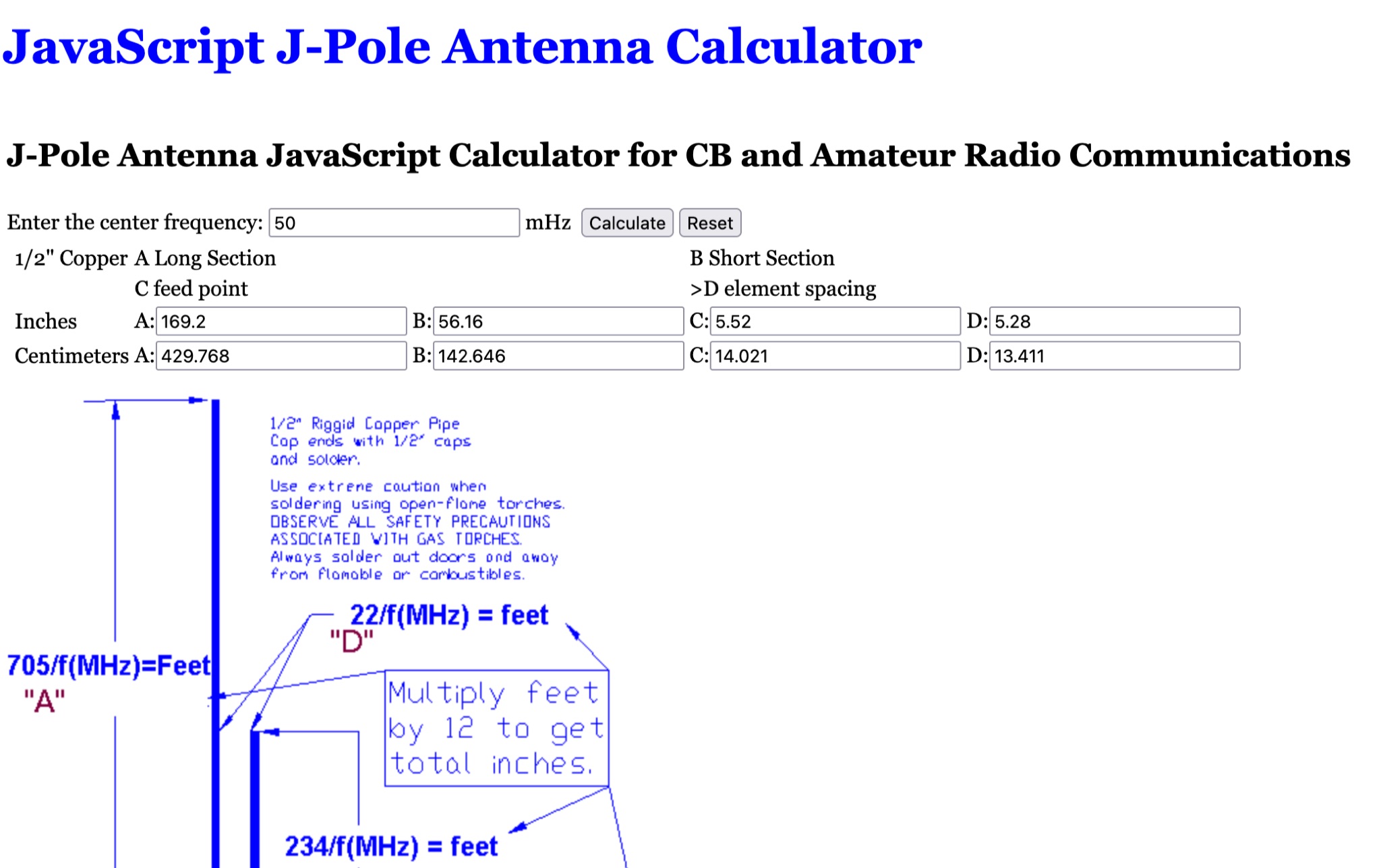 This page provides a detailed guide on the J-pole antenna, an end-fed half-wave antenna matched to the feedline by a quarter-wave transmission line stub. It covers the characteristics, construction materials, feeding options, and mounting considerations for optimal performance. The information is useful for hams or amateur radio operators looking to build and set up a J-pole antenna for improved transmission and reception.
 -
 Demonstrates the design and modeling of a **160m** vertical antenna, dubbed the "WindoVert," specifically for urban amateur radio operators with limited space. The resource covers the theoretical underpinnings of antenna height and radiation patterns, using EZNEC software to analyze current distribution and 3D radiation patterns for various configurations, including a Marconi-style "T" antenna. It details the integration of existing antenna components, such as a Carolina Windom balun and line isolator, into the new vertical setup, and the practical measurement of feedpoint impedance using an antenna analyzer. The article further explores the challenges of achieving low-angle radiation on Top Band, emphasizing the critical role of radial systems and mitigating ground loss. Author VE1ZAC presents EZNEC models illustrating the impact of lumped components and discusses the practical considerations of resonant frequency adjustment and impedance matching for **QRP** operation. The text details the calculation of required loading coil inductance and capacitance, and shares field results, including successful DX contacts on 160m and unexpected excellent performance on 30m.
 -
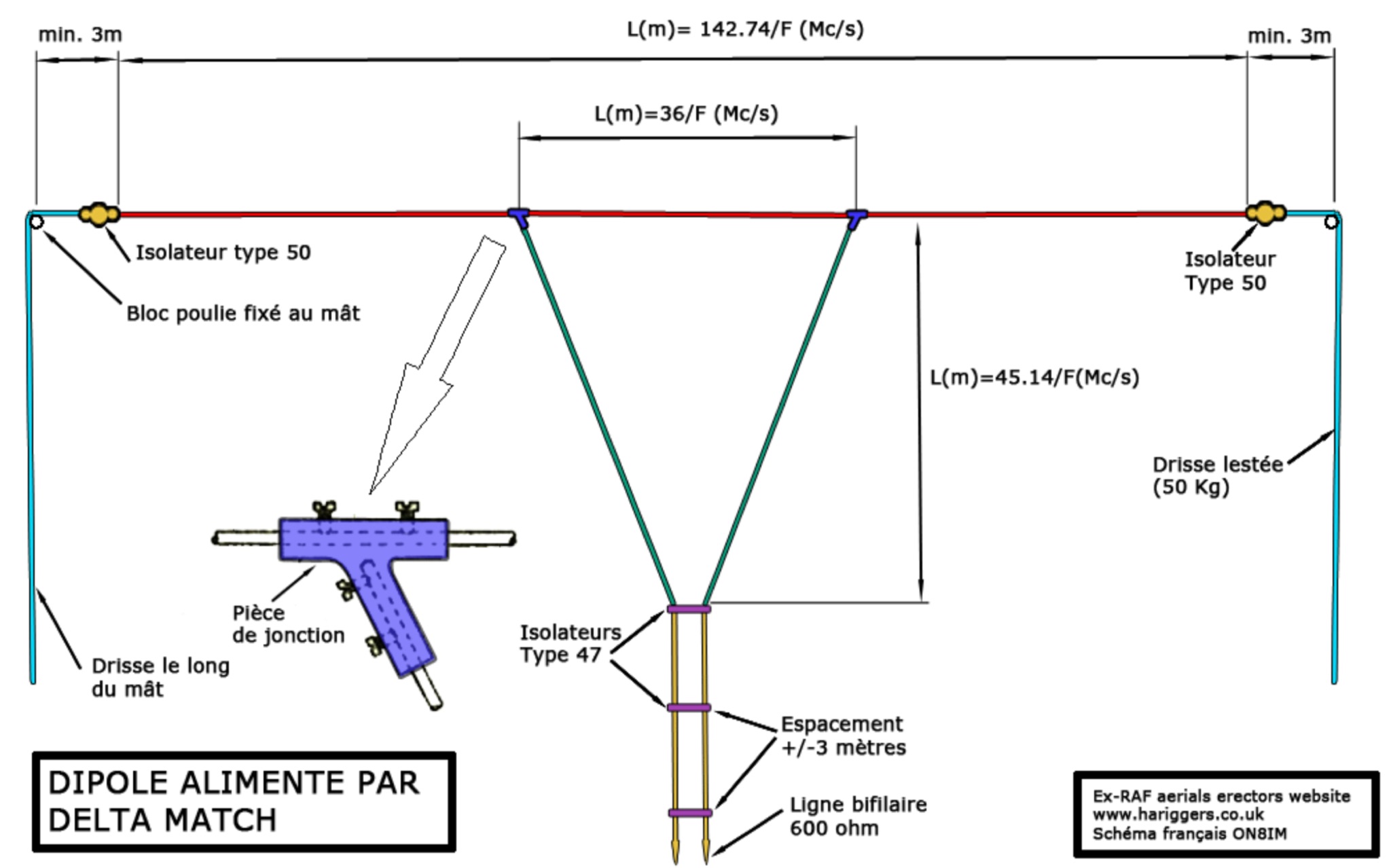 This page provides a detailed example of the modeling and analysis of an 80m delta dipole antenna with a 600-ohm bifilar feedline. The model is based on antennas used by the RAF from 1940 to 1970. It covers the original model specifications, conductor mass calculations, resonance frequency observation, geometry adjustment steps, and final antenna dimensions. The content includes theoretical formulas, resonance frequency calculations, and practical steps for adjusting the antenna for optimal performance. Overall, it serves as a practical guide for hams looking to understand and optimize the performance of a delta dipole antenna for the 80m band.
 -
 HamDaily presents a **real-time dashboard** for amateur radio operators, integrating live propagation data, current space weather conditions, and a continuously updated stream of DX, POTA, and SOTA spots. The platform also curates news headlines and articles from more than 16 distinct amateur radio sources, offering a centralized hub for daily information. Beyond its real-time data feeds, HamDaily includes practical tools such as practice exams for licensing, a Morse code trainer, a repeater finder, and satellite pass predictions, catering to both active operators and those preparing for their licenses. The resource distinguishes itself by fusing diverse data streams into a single, cohesive interface, allowing operators to quickly assess band openings and relevant activity. The "Today's Roundup" section provides a daily digest of featured articles, ranging from technical insights like "My one-day Tech class 'bag of tricks'" by KB6NU to operational accounts such as QRPer's "Eight Parks, One Missing Mast, and the Midnight Sun: A CW-Only POTA Trek." This aggregation of content, combined with **live band data** and Kp index readings, offers a comprehensive operational awareness tool for the ham radio community.
 -
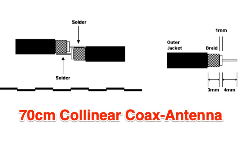 The 9 dB gain 70cm collinear antenna project details the construction of an 8-element array using RG58/U coaxial cable, designed for the 444 MHz band. Each half-wavelength section of RG58/U is precisely calculated, accounting for a velocity factor of 0.66, ensuring optimal resonance and performance. The design incorporates a quarter-wave wire element at the top and a quarter-wave aluminum or copper tube at the bottom, with specific length calculations provided for each component. Construction involves careful cutting and soldering of the coax elements, exposing the center conductor and braid, and tinning the braid for robust connections. The feed point connection to the main RG58/U coax is also thoroughly described, ensuring proper impedance matching for the UHF band. Encased in PVC pipe for weather protection, this homebrew antenna offers a cost-effective solution for amateur radio operators seeking a reliable UHF antenna. The article includes step-by-step instructions, making it accessible for those interested in building their own antennas.