Search results
Query: 7 MHz band
Links: 530 | Categories: 11
Categories
- Operating Modes > 70 MHz
- DX Resources > Beacons > 10 meter beacons
- Antennas > 20M
- Antennas > 23cm
- Antennas > 2M
- Antennas > 30M
- Antennas > 40M > 40 meter Dipole Antennas
- Antennas > 40M > 40 meter Yagi Antennas
- Antennas > 4M
- Antennas > 6M > 6 meter Moxon Antennas
- Radio Equipment > HF Vertical Antenna > Maldol MFB-300
-
 The GM4JJJ VHF and EME pages document David's extensive work in Earth-Moon-Earth (EME) communication, specifically on the 144 MHz band, and his involvement in amateur radio astronomy. The resource details his station setup and operational experiences, providing insights into the technical challenges and rewards of bouncing signals off the moon. It offers a glimpse into the specialized equipment and techniques required for successful EME contacts, a niche but highly rewarding aspect of amateur radio. David's content shares practical applications and field results from his EME endeavors, which can be particularly useful for hams contemplating or actively pursuing moonbounce operations. The information, while not a step-by-step guide, implicitly compares the complexities of EME with more conventional VHF/UHF operations, highlighting the significant power and antenna gain necessary to overcome path losses. This resource serves as a testament to the advanced capabilities achievable in amateur radio.
 -
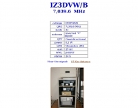
 Demonstrates the operational status and reception reports for the SK6RUD/SA6RR QRPP beacons, which transmit on 478.9 kHz, 1995 kHz, 10.131 MHz, and 40.673 MHz. These beacons utilize extremely low power, with the 630-meter beacon operating at approximately 0.1 watt ERP into an L-antenna, showcasing the potential for long-distance contacts under favorable propagation conditions. The site details the specific frequencies and antenna types employed, such as a vertical at 500 kHz and a 1/4 vertical for higher bands. The resource compiles over 10,530 reception reports from amateur radio operators worldwide, logging details such as date, time, band, RST signal report, locator, distance, and receiver setup. Notable long-distance reports include a 500 kHz reception by AA1A-Dave from 5832 km in 2008 and a 10.133 MHz reception by ZL2FT-Jason from 17680 km in 2010, illustrating the global reach of these low-power transmissions. Each log entry provides specific equipment used by the reporting station, including transceivers like the Yaesu FT817, ICOM IC-7300, and various antenna configurations such as coaxial mag loops, inverted Ls, and end-fed wires. The primary objective of the SK6RUD beacons is to challenge conventional notions of power requirements for effective two-way communication, proving that contacts over significant distances are achievable with minimal output. The site also includes a submission form for new reception reports, fostering community engagement and continuous data collection on propagation phenomena across different bands. The detailed logs offer practical insights into real-world propagation characteristics and the efficacy of QRPP operations.
 -
 A 5 element yagi beam antenna for ten meters band with full dimentsions, eznec file and coax match informations for 50 ohms feed line
 -
 An homebrew project for a 4 elements yagi monoband antenna for the 10 meters by 9M2MSO
 -
 An high gain long yagi antenna, seven elements, for six meters band
 -
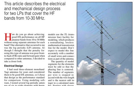 This QST article describes the electrical and mechanical design process for two LPs that cover the HF bands from 10-30 MHz
 -
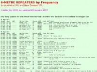 Presents a detailed compilation of **6-meter** voice repeaters operating within the 53-54 MHz segment across Australia (VK) and New Zealand (ZL), providing essential data for local and visiting radio amateurs. Each entry specifies the repeater's output and input frequencies, its assigned callsign (where applicable), the primary service area, current operational status (e.g., operational, under construction, scrapped), and a **Maidenhead grid locator**. The resource also includes the date the repeater was last heard or updated, offering insights into its recent activity. This listing is meticulously maintained by VK2KFJ, who updates entries based on personal observations and confirmed reports from other operators. It serves as a practical reference for hams seeking to utilize the 6-meter band for local communication via repeaters, particularly for those engaged in mobile or portable operations within the specified regions. The data helps operators configure their transceivers correctly for accessing these vital communication hubs. Beyond the repeater details, the page also notes common 6-meter FM voice simplex frequencies, such as the 52.525 MHz international call frequency, and lists historical packet simplex frequencies, though their current operational status is uncertain. This comprehensive approach ensures that operators have a broad overview of 6-meter activity in VK and ZL.
 -
 Over 100 amateur radio beacon audio files are presented, offering a direct auditory experience of propagation conditions across a wide spectrum of frequencies, from 1.8 MHz to 47 GHz. These recordings, primarily captured by IW3FZQ and IK3NWX, document signals from beacons such as DK0WCY, IY4M, GB3RAL, and S55ZRS, providing a valuable resource for **propagation study** and **beacon monitoring**. Each entry in the list specifies the beacon's callsign, its operating frequency in kHz, and the recording operator. This compilation includes signals from beacons located in various grid squares like JN55VF, JO44VQ, and IO91IN, illustrating diverse geographical origins. The frequencies covered span the 160m, 80m, 40m, 30m, 20m, 17m, 15m, 12m, 10m, 6m, 4m, 2m, 70cm, 23cm, 6cm, 3cm, 1.2cm, and 6mm amateur bands. Users can listen to these recordings to identify characteristic beacon tones and observe signal strength variations. The resource also invites other radio amateurs to contribute their own beacon audio files, fostering a collaborative archive of propagation data. The last update to this collection was on March 24, 2009, indicating a historical snapshot of beacon activity. Accessing the files requires the Real Player software.
 -
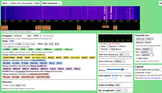 This online WebSDR is located near Corinne, Utah, has coverage on all U.S. amateur HF, MF and LF bands, 2 meters, the bottom 1 MHz of 6 meters, and several shortwave broadcast bands.
 -
 Article by G4AON about a 4 and 2 Element Quad Antennas for the 6m band
 -
 The page discusses the concept of a 2-element Parasitic Ground Plane antenna for the 40-meter band. It includes a conversation between amateur radio operators discussing modeling results and design considerations for the antenna. The author shares insights on radial configurations and the impact on antenna efficiency and pattern.
 -
 70 MHz transverter, 4m band, by G3XBM
 -
 Presents SWR analysis of an **Alpha-Delta DX-LB Plus** multiband wire antenna, installed as an inverted-V at 40 feet with ends at 15 feet, using an RigExpert AA-54 analyzer. The resource provides a full SWR sweep from 0.1 MHz to 54 MHz, followed by detailed SWR graphs for individual amateur bands including 160m, 80m, 40m, 30m, 20m, 17m, 15m, 12m, 10m, and 6m. The analysis highlights the narrow bandwidth on 80m and 160m due to loading coils, necessitating tuning for specific operating frequencies. It notes excellent SWR performance across the entire 40m band and good results on 10m, also requiring tuning. The author shares personal experience with the antenna, including a 17,000 km QSO on 20 meters, and discusses plans to replace it with a homebrewed parallel **fan-dipole**.
 -
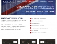 Linear Amp UK specializes in the design and production of high-quality linear amplifiers, offering models for HF, VHF, and UHF amateur and commercial applications. The company emphasizes nearly 30 years of experience in crafting each unit, ensuring robust performance and longevity. Their product line includes amplifiers engineered for a 100% duty cycle, promoting continuous and reliable operation across various modes. The amplifiers feature solid, dependable designs, ensuring quiet and effortless performance during transmission. Each unit is hand-built to stringent standards, reflecting a commitment to durability and operational stability. All products are CE approved, confirming compliance with European safety and environmental directives, and come with a standard two-year warranty, providing assurance to operators. Key specifications often include coverage for 1.8-30MHz (WARC bands), 50MHz, 70MHz, and 144MHz, utilizing tubes such as 811, 572, 811A, 572B, GS35, GS35B, 8877, 3CX1500, and _3CX1500A7_ in their designs.
 -
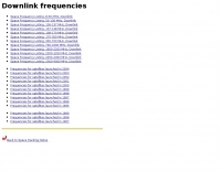 This resource provides a detailed historical record of satellite downlink frequencies, systematically organized by both frequency range and the satellite's launch year. It presents extensive listings covering segments from 8 MHz to 9000 MHz, including specific breakdowns like 136-137 MHz and 1600-2200 MHz. The data is segmented into distinct frequency blocks, offering granular information for various bands. The content delineates frequencies for satellites launched across several decades, with specific sections for years such as 2004, 1999, and extending back to 1967. This chronological organization allows for tracking the evolution of satellite communication frequencies over time. The resource serves as a reference for identifying operational downlink frequencies of historical space assets, which is particularly useful for satellite enthusiasts and those interested in _space tracking_ or _vintage satellite_ communications. The utility of this compilation lies in its specific historical data, providing a unique perspective on past satellite operations and frequency allocations.
 -
 The resource details the construction of a multiband trap-style Inverted-V antenna designed for operation on 3.5 MHz, 7 MHz, 14 MHz, 21 MHz, and 28 MHz. It presents specific winding data for the traps, including the number of turns, wire gauge, and coil former dimensions, crucial for achieving resonance on the target bands. The document provides a parts list and a diagram illustrating the antenna's physical layout and trap placement. It outlines the process for building the traps using PVC pipe formers and specifies the required capacitor values for each trap. The design emphasizes a practical approach to achieving multiband operation with a single feedline, a common goal for HF operators with limited space. The document includes a table with antenna segment lengths for each band, allowing for precise replication of the design. It also offers insights into tuning and adjustment, ensuring the antenna performs optimally across the designated amateur radio bands.
 -
-
-
 The HyGain LJ-153BA a monoband 3 element Yagi, designed for the 15 m band 21.00 - 21.45 MHz
 -
 Amplifier repair and conversion, specialize in converting HF amplifiers to operate as monoband amps on 50 MHz
 -
 For over 20 years, bhi Ltd has specialized in digital signal processing (DSP) technology to mitigate noise and interference across various radio channels. Their product line, including the _ParaPro EQ20 Audio DSP_ units, focuses on enhancing receive audio quality, even for operators without significant noise issues, by offering precise parametric equalization to suit individual hearing preferences. The core offerings are noise-cancelling speakers and in-line modules, specifically engineered for amateur radio applications, but also adapted for commercial, PMR, and marine radio systems. The company provides audio demonstrations, such as a 20m SSB example and a 14MHz band filter comparison, allowing users to hear the effectiveness of their DSP units against common QRM sources like plasma TV interference or diesel engine noise. Located in Burgess Hill, West Sussex, UK, bhi Ltd emphasizes clear voice communications, aiming to remove unwanted noise and leave only intelligible speech.
 -
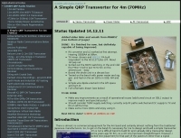
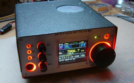 An SSB radio for the HF bands will be presented. Featuring 12 to 20 Watts of output power (depending on DC supply), full DDS frequency generation, covering 6 major frequency bands (1.8, 3.5, 7, 14, 21 and 28 MHz) within the short wave amateur radio spectrum. The rig also features colored LCD and front panel backlight.
 -
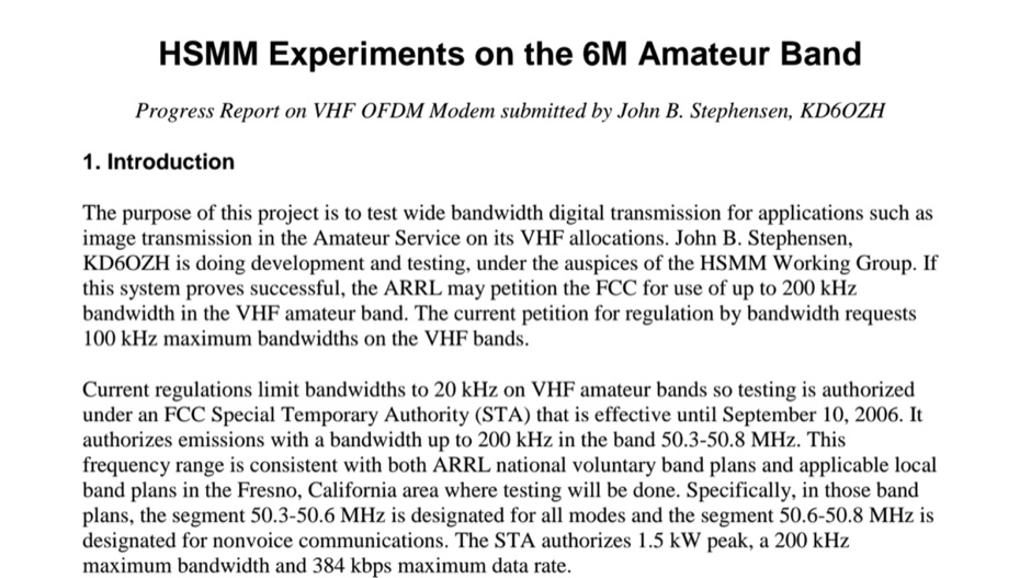
 A 200 kHz bandwidth digital transmission system for image transfer in the Amateur Service is under development, specifically targeting VHF allocations. John B. Stephensen, KD6OZH, leads this project under an FCC Special Temporary Authority (STA) valid until September 10, 2006, authorizing emissions up to 200 kHz bandwidth in the 50.3-50.8 MHz segment. Current regulations typically limit bandwidths to 20 kHz on VHF amateur bands, making this STA crucial for testing wideband digital modes. The modem, a modified **OFDM** (Orthogonal Frequency Division Multiplexed) unit, was initially tested on the 70-cm band. It splits a high-rate data stream into multiple low-rate subcarriers to mitigate multipath echoes. The system uses a DCP-1 card with a Xilinx XC3S400 FPGA and Oki Semiconductor ML67Q5003 microcontroller. The transmitter, located at 36d 46m 30s N, 119d 46m 22s W, generates 150 WPEP into an 8 dBi gain vertical antenna, while the mobile receiver uses a Ham-stick. Three data formats for 50, 100, and 200 kHz channels are being tested, with encoded data rates of 96, 192, and 384 kbps. Verilog code for the VHF OFDM modem is 95% simulated, with modifications from the UHF version including increased filter coefficient precision and a change from Ungerboeck **TCM** to BICM for improved performance over fading paths. Final tests will involve one-way over-the-air measurements of bit error rates and coverage area.
 -
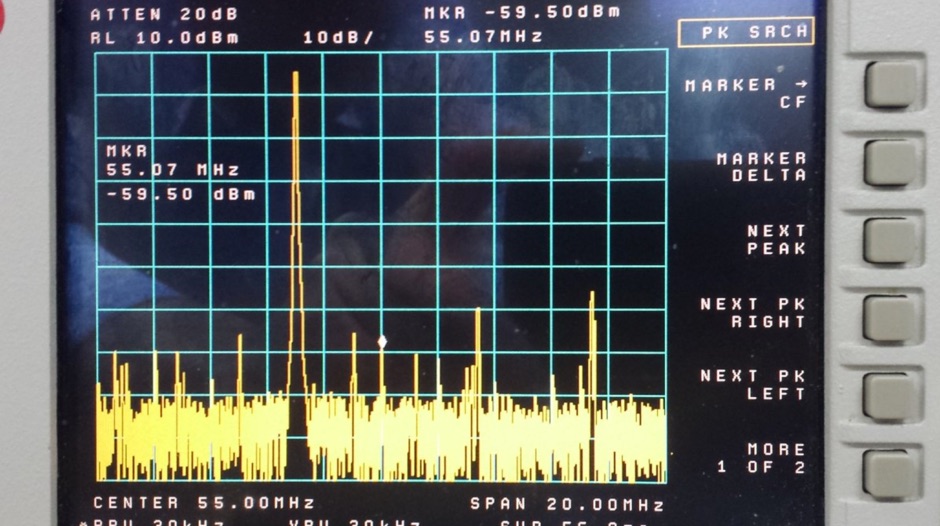
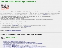 This resource provides a unique historical audio archive of 50 MHz DX contacts, documenting significant F2 and Es propagation events experienced by PA2S (formerly PA2HJS) since 1978. The collection includes recordings of beacons and two-way QSOs with stations across North America, South America, Asia, Australia, Europe, and Africa. Specific entries detail contacts with rare DX entities such as ZS6PW, VE1AVX, C5AEH, J52US, TR8CA, LU8MBL, VK8ZLX, and various Japanese stations, often noting the mode (SSB or CW) and propagation type. The archive also highlights challenging pile-up situations and frustrating near-misses during major openings. The recordings, initially in RealAudio format for solar cycles 21 and 22 and later in MP3 for cycle 23, offer a practical illustration of 6-meter band conditions over several solar cycles. The content allows hams to listen to actual signals from different continents, observing signal characteristics like typical TEP fading from 5H3RA or strong F2 backscatter from OZ1BVW. It provides a comparative perspective on propagation effectiveness between solar cycles, noting that cycle 23, while not as robust as previous cycles, still yielded interesting openings. The archive serves as a valuable educational tool for understanding real-world 50 MHz DXing and propagation phenomena.
 -
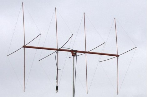
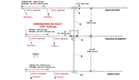
 Six elements yagi antenna for 6 meters band. This antenna design is based on the QuickYagi 4 software by WA7RAI, uses a 6.5 m boom, feature 12.0 dBi gain and 35dB front/back
 -

-
 An homebrew project of a full wave delta loop antenna for the 40 meters band with dimensione, picture and assembling instructions in Indonesian
 -
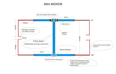 Homemade moxon antenna for the 40 meter band. This article is not very descriptive but includes some very detailed images
 -
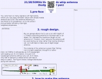
 A vertical antenna project for the 7MHz made with some spare parts. Based on a broken 20 foot fishing pole, it is based on a good ground system made with radials and a capacitive hat done to increase the global radiation resistance of the antenna. A custom loading coil is also included in this project to perfectly tune the antenna to the CW portion of the 40 meters band.
 -
 Demonstrating the construction of a short dipole antenna tailored for the 60 meter band, this resource provides detailed instructions for radio enthusiasts with limited space. The design incorporates inductive loading using two inductors (L1/L2) made from PVC tubes, allowing for effective operation on 5 MHz. The antenna consists of 12 meters of wire, divided into four sections, with specific dimensions and materials outlined for optimal performance. Results from users indicate that this antenna can significantly enhance DXing capabilities on the 60 meter band. Feedback from operators suggests that while the design is effective, adjustments may be necessary based on individual setups, such as coil diameter and wire gauge. Many users report successful construction and operation, with some experimenting with variations to improve resonance. The practical application of this antenna design has led to successful contacts and improved signal quality, making it a popular choice among 60 meter band operators.
 -
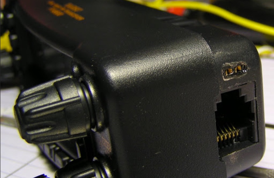 Modoification for the Yaesu FT-8800 144/430 MHz dual band FM transceiver
 -
 Organized to promote operation on the amateur bands above 420 MHz
 -
 An EH Antenna for 14 MHz by EB3EMD based on an original project by F5SWN
 -
 A 4 element yagi beam antenna for the 17 meters band with pictures and element dimension and spacing
 -
 KN-Q10 Assembly Manual four band (3.5, 7, 14 & 21MHz) 5W SSB/CW transceiver kit Translated by BD6CR/4,
 -
-
 The Icom AH-4 autotuner operates efficiently across multiple HF bands, providing seamless automatic tuning for antennas from 3.5 MHz to 54 MHz. Its robust design allows for outdoor installation, making it suitable for field operations and fixed stations. The unit interfaces with Icom transceivers via a control cable, enabling automatic band switching and tuning. The AH-4 is capable of handling up to 120 watts of RF power, ensuring compatibility with most amateur radio setups. Its weather-resistant casing and compact form factor make it a versatile choice for operators requiring reliable performance in diverse environments. Field tests demonstrate the AH-4's ability to maintain low SWR across its operational range, enhancing signal quality and transmission efficiency. Compared to manual tuners, the AH-4 offers significant time savings and ease of use, particularly in rapidly changing band conditions. Its integration with Icom radios simplifies operation, eliminating the need for manual adjustments. The autotuner's performance is consistent with other high-end models, providing a cost-effective solution for amateur operators seeking dependable tuning capabilities without sacrificing performance.
 -
 An information paper by the International Amateur Radio Union, History of 40m allocation, propagation properties of 7 Mhz band
 -
 Message list about 903 Mhz. and above bands. Use various VHF reflectors for the 432 and lower bands. Most traffic will be about 2304 and above.
 -
 Details the construction of an **HF converter** designed by M1GEO, George Smart, specifically to extend the frequency range of the FunCube Dongle Pro (FCD) for amateur radio reception. The FCD natively covers 64 to 1,700 MHz, but this project enables reception from 0 Hz to 64 MHz by up-converting signals to the FCD's operational range. It employs a **double-balanced mixer** with a 100 MHz local oscillator (LO) to translate incoming HF signals; for instance, a 1 MHz signal appears at 101 MHz within the FCD's passband. The design incorporates a 7th-order Chebyshev low-pass filter with a 62 MHz cutoff frequency at the input to mitigate image frequencies, ensuring cleaner spectral presentation. George provides the schematic, PCB masks, and Gerber files for replication, noting that Far Circuits also offers PCBs. The resource includes test results for the low-pass filter and measurements of LO leakage, identifying -36.8 dBm at 100 MHz as a potential sensitivity concern. M1GEO discusses potential improvements, such as adjusting the mixer's LO drive, adding a balance pot, or incorporating a post-mixer high-pass filter to reduce LO breakthrough. Audio recordings from 40m and 17m demonstrate the converter's performance with WRplus SDR software.
 -
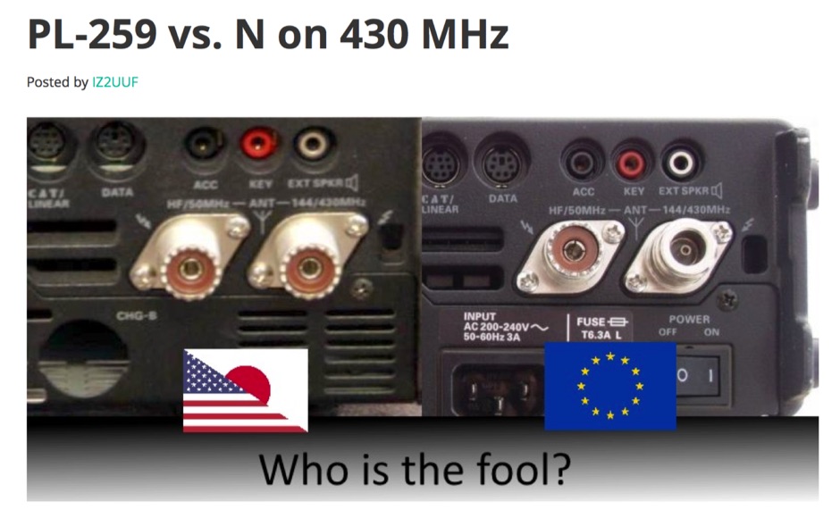 A test and comparison of real attenuation of N-type connectors and PL-259 connectors on UHF bands, domonstrating that connectors are almost equivalent.
 -
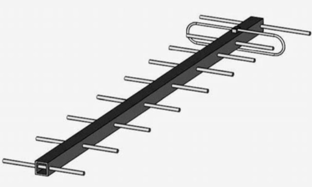 The author who works successfully via EME on this band wants to describe his own yagi design and give some of hints for the construction. by Heinrich F. Reckemeyer, DJ9YW
 -
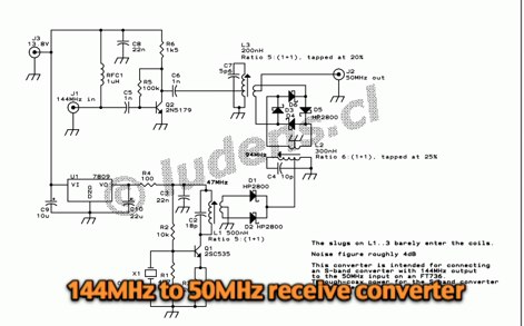 A simple accessory for a satellite station, that allows using a 6 meter capable radio in conjunction with a typical S-band to 2 meter converter
 -
 This kind of antenna has grown in popularity over the last years because it gives you a decent performance and triband capabilities. But its 50 MHz design is far from optimal. Here you can learn how to improve its 50 MHz performance in a very easy way.
 -
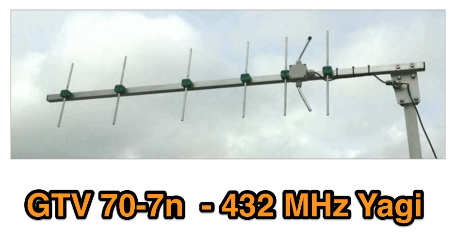 A 70 cm yagi designed for EME + SSB narrow bandwidth version, strictly G/T breeding. This little Yagi has a high F/B, which makes it quite useful as a contest stack
 -
 A 160W linear amplifier for 4 meters band based on GI0GDP
 -
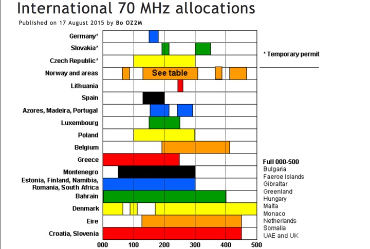 The Four Metres website offer a global overview graph of the four meter band plans world wide
 -
 This project is based around the recent HF1 QRP transceiver by Ashhar Farhan, VU2ESE. The transceiver is an interesting SSB design with wide tuning range from 0-30MHz and should cover several amateur bands. The schematic for the transceiver can be found on the Minima mail list in this post with a PDF attachment
 -
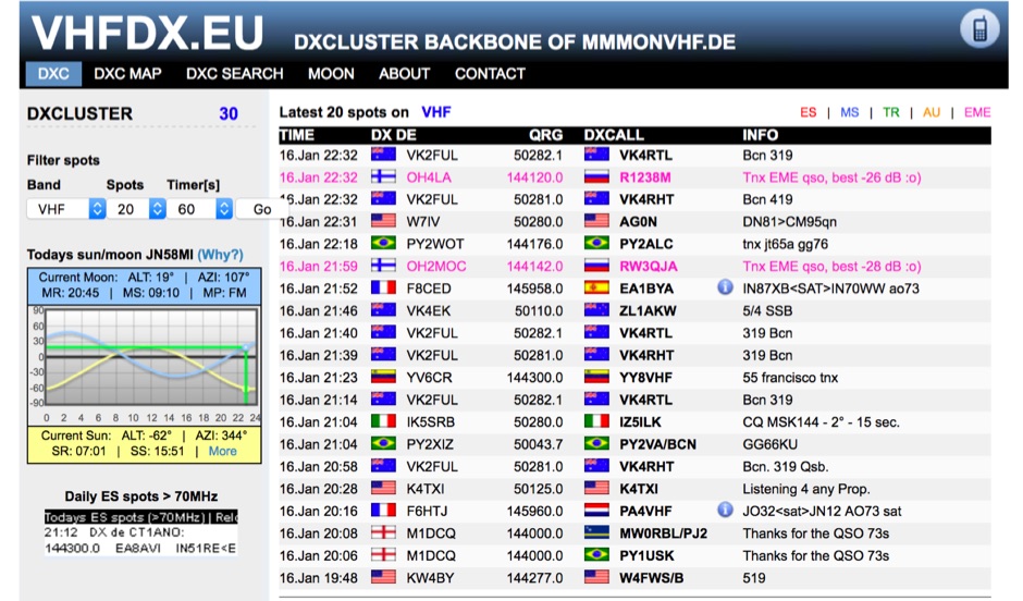 Presents the VHFDX.EU web cluster, a specialized resource for VHF, UHF, and microwave DX spotting. It details the cluster's functionality, including real-time spot aggregation and a DXCluster Map interface for visualizing activity. The resource highlights its integration with the MMMonVHF backbone, ensuring a robust data flow for monitoring band openings and propagation events across higher frequencies. It also references reviews of the ON4KST and N0UK chat systems, which are frequently used in conjunction with VHF DX operations. The platform offers a mobile-optimized view for on-the-go access to DX spots, catering to portable and mobile operators. It further provides daily ES (Sporadic E) spot summaries, a critical feature for VHF operators tracking this specific propagation mode. The cluster serves as a central point for operators to share and receive information on rare grid squares, contest activity, and general band conditions above 50 MHz.
 -
 This resource, a blog from the Penang Amateur Radio Club (PARC), offers insights into various aspects of amateur radio in Malaysia. One post details monitoring Automatic Terminal Information Service (ATIS) on the 2m band, providing specific frequencies like 122.750 MHz AM for Butterworth and 126.400 MHz AM for Penang, along with sample aviation weather and operational data. Another entry critiques the lengthy and costly process of obtaining an amateur radio license in Malaysia, contrasting it with the more streamlined FCC licensing system in the United States, citing a 1-year wait and RM 414 (USD 125) for 10 years in Malaysia versus 3 weeks and USD 14 for 10 years in the US. The blog also covers internal club matters, such as the 2007 Annual General Meeting (AGM) attendance and council elections, highlighting member dissatisfaction with outdated newsletters and a call for "reformasi." Additionally, it presents local phonetic alphabets in Bahasa Malaysia and Chinese, and discusses monitoring AM broadcast bands for international stations like Voice of America on 1575 kHz and Zhong Yang Ren Min Guang Bo Dian Tai on 1134 kHz, offering alternatives to local 2m repeater chatter. The author, "firstclass," shares personal observations and criticisms regarding the Malaysian ham radio landscape.