Search results
Query: loop
Links: 448 | Categories: 13
Categories
- Antennas > 40M > 40 meter Delta Loop Antennas
- Antennas > 40M > 40 meter Loop Antennas
- Antennas > 40M > 40 meter Magnetic Loop Antennas
- Antennas > Delta loop
- Manufacturers > Antennas > HF > Delta Loop Antennas
- Antennas > Loop
- Manufacturers > Antennas > HF > Magnetic Loop
- Antennas > Magnetic Loop
- Antennas > 160M
- Antennas > 20M
- Antennas > 30M
- Antennas > Hentenna
- Antennas > Receiving
-
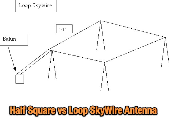 An article at NFARL web site about differences in setting up a half-square antenna versus a Loop Skywire by W4QO
 -
 Antenna model for a diamond loop wire antenna for the 40 meter band
 -
 Demonstrates the operational status and reception reports for the SK6RUD/SA6RR QRPP beacons, which transmit on 478.9 kHz, 1995 kHz, 10.131 MHz, and 40.673 MHz. These beacons utilize extremely low power, with the 630-meter beacon operating at approximately 0.1 watt ERP into an L-antenna, showcasing the potential for long-distance contacts under favorable propagation conditions. The site details the specific frequencies and antenna types employed, such as a vertical at 500 kHz and a 1/4 vertical for higher bands. The resource compiles over 10,530 reception reports from amateur radio operators worldwide, logging details such as date, time, band, RST signal report, locator, distance, and receiver setup. Notable long-distance reports include a 500 kHz reception by AA1A-Dave from 5832 km in 2008 and a 10.133 MHz reception by ZL2FT-Jason from 17680 km in 2010, illustrating the global reach of these low-power transmissions. Each log entry provides specific equipment used by the reporting station, including transceivers like the Yaesu FT817, ICOM IC-7300, and various antenna configurations such as coaxial mag loops, inverted Ls, and end-fed wires. The primary objective of the SK6RUD beacons is to challenge conventional notions of power requirements for effective two-way communication, proving that contacts over significant distances are achievable with minimal output. The site also includes a submission form for new reception reports, fostering community engagement and continuous data collection on propagation phenomena across different bands. The detailed logs offer practical insights into real-world propagation characteristics and the efficacy of QRPP operations.
 -
 Use this online calculator to determine the length of a full-wave loop antenna from the frequency. Both metric and English units of measurement are supported. Quarter-wave matching section lengths are also calculated.
 -
 The TMB-1 is an RF amplifier unit / receiving accessory that can be used with a low-impedance broadband loop, a high-impedance terminated loop (such as a Pennant, Flag, or Kaz Delta), and whip (telescoping rod) antennas.
 -
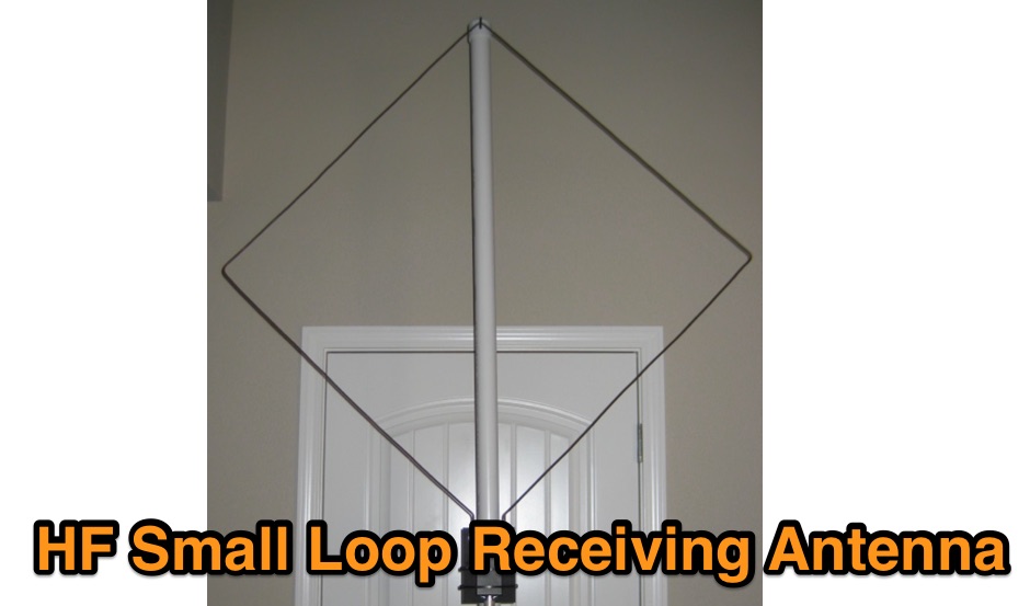 Receive-only loop antennas have some nice response characteristics that make them ideal when used for reception of skywave signals.
 -
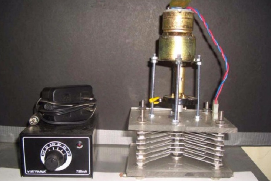
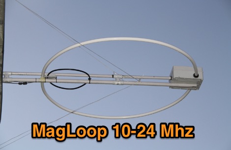
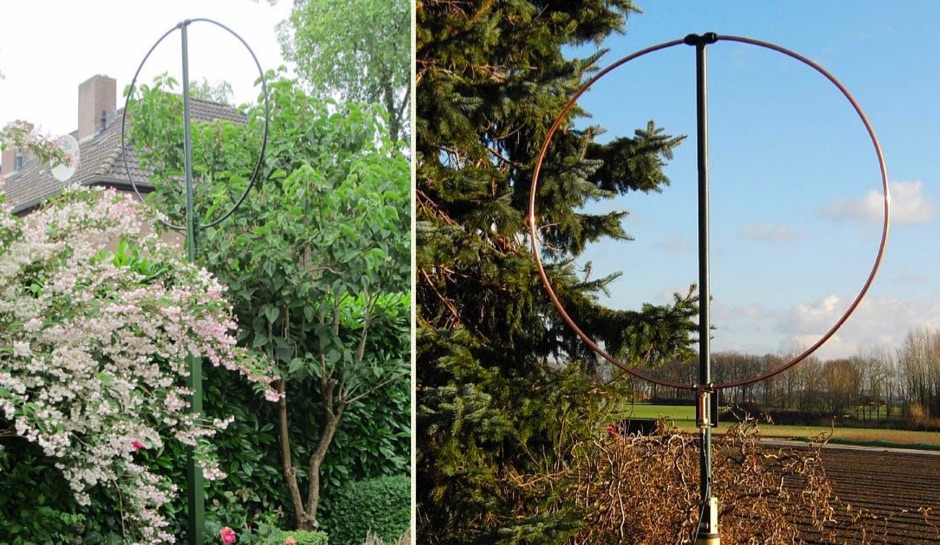
 A motor tuned magnetic loop antenna that can work from 14 MHz to 30 MHz
 -
 Picture and reference links for STL Small tumed loops antennas by DJ3TZ
 -
 Delta loop antennas for 40 meters plans and comparison of some models
 -
 A system designed to automatically tune small transmitting magnetic loop antennas, particularly beneficial for **contest operations** where rapid frequency changes are common. The core of the system involves a PC-based control application, AutoCap, written in C#, which monitors antenna SWR via an external meter and commands a motor interface to adjust the loop's variable capacitor. The software is compatible with Windows and Linux via the Mono framework, offering a graphical user interface for monitoring system status, SWR, power, and motor commands. Key components include one or more magnetic loop antennas equipped with DC or stepper motors for capacitor adjustment, an SWR meter with data output (such as the Telepost LP-100A or a homebrew serial/USB SWR meter), the AutoCap PC software, and a motor interface. The most effective motor interface utilizes an **Arduino-based controller** with custom firmware, providing precise control over both simple DC motors and stepper motors, and supporting features like motor braking for finer adjustments. The system allows for configurable SWR thresholds, pulse widths, and motor effort settings to optimize tuning speed and resolution. Optional radio integration provides frequency hints, enabling the algorithm to learn the relationship between motor actions and resonant frequency, thereby speeding up initial tuning responses. The software also supports antenna profiles, allowing operators to save and recall specific configurations for different loops, including accumulated frequency hint data.
 -
 The HF horizontal loop has been around for many years now. This article includes a YouTube video and discusses the reasons for looking at this antenna, its design, and its installation. There are some on-air comparisons against three regular double bazooka (coax) dipoles and the Par SWL End-Fed antenna.
 -
 A 2 element 40 meters band parasitic delta loop antenna project with pictures and details
 -
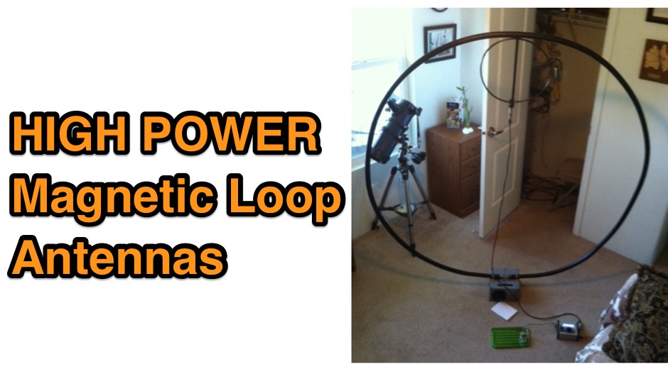 Magnetic Loop Antennas for The Radio Operator with Limited Space, a two part series of articles on how to construct a magnetic loop antenna, including directions on selecting high voltage tuning capacitor
 -
 Dipole, inverted V, full wave loop and grond plane antenna quick reference plans
 -
 Magnetic Loop Antenna for 20/15m with Remote Tuning by George Szymanski
 -
 Schematic diagram and description of a magnetic loop antenna that works from 10 to 20 meters band, made from junk
 -
 Operating magnetic loop antennas requires careful consideration of RF safety, particularly regarding near-field magnetic field intensity. This resource presents calculations for magnetic field strength (H-field) at various distances from a magnetic loop, emphasizing that the H-field is significantly higher than the E-field in the near-field region due to the inductive nature of the radiating element. It provides specific formulas and examples for determining safe operating distances based on power levels and loop dimensions, crucial for compliance with RF exposure limits. The analysis compares calculated H-field values against FCC and ICNIRP maximum permissible exposure (MPE) limits for controlled and uncontrolled environments. It demonstrates that even at QRP power levels (e.g., 5W), the H-field can exceed MPE limits within a few feet of the antenna, necessitating greater separation distances than often assumed for electric field considerations. The practical application of these calculations helps amateur radio operators configure their stations to ensure personnel safety and regulatory compliance when deploying compact, high-Q magnetic loop antennas.
 -
 Loop Antenna Basics and Regulatory Compliance for Short-Range Radio
 -
 Testing performances of indoor antenna. A comparison of a magnetic loop antenna vs a classic wire dipole done using wsprlite on 30 meters band.
 -
 A magnetic loop antenna for the VHF band, featuring a high gain that can be compared to a quarter wave vertical antenna
 -
 Digital radio mondiale DRM products, measuring tools, Magnetic field probes, RF power meters, Broadband loop antennas, DRM devices and services
 -
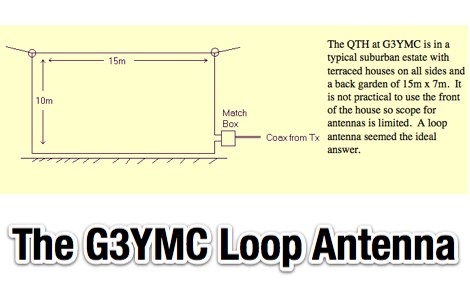 Experiences with Loop antennas at G3YMC include some loop antenna tests and theory by G3LHZ
 -
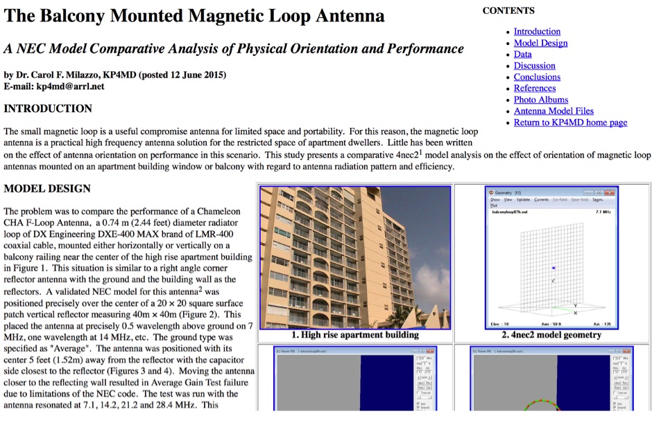 A NEC Model Comparative Analysis of Physical Orientation and Performance. The small magnetic loop is a useful compromise antenna for limited space and portability. For this reason, the magnetic loop antenna is a practical high frequency antenna solution for the restricted space of apartment dwellers
 -
 Antennas and Accessories for Satellite Radio and AM FM HD Short Wave Radio, satellite antenna, shortwave magnetic loops.
 -
 Air conditioning soft copper tubes are perfect for loop construction. If you want to try a loop you must have an air variable capacitor or a vacuum variable capacitor. Article by PY1AHD
 -
 The **136kHz Vertical Antenna** at G3YMC employs a Butternut HF2V structure, standing 10m tall. It integrates a 6.5mH loading coil to achieve resonance, with a matching transformer for impedance adjustment. The antenna's configuration includes top loading via a 12m horizontal wire, enhancing capacitive impedance. Initial measurements indicated a high impedance of around 300 ohms, necessitating a transformer for a 50-ohm match. Despite challenges with ground losses, the vertical antenna has shown improved performance in specific directions, filling nulls present in the previous loop antenna setup. The tuning remains broad, with variations due to environmental factors affecting the matching. Ongoing adjustments and comparisons with the loop antenna will continue to refine its effectiveness.
 -
 An homebrew project of a full wave delta loop antenna for the 40 meters band with dimensione, picture and assembling instructions in Indonesian
 -
 Experimentig magnetic loop antennas for VHF and HF by M0UKD
 -
 22 Different Wire Antennas for the 160 Meter Band, Random Length Radiator Wire, delta loop, loop antennas, off-centered antennas, sloper, dipoles, Z antenna, Zepp and Clothesline Antennas
 -
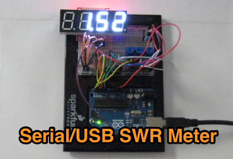 A low-cost SWR meter project based on Arduino that works with AutoCap automatic antenna tuner for magnetic loop antennas
 -
 Sensitivity of multi turn receiving loops William E. Payne, N4YWK
 -
 The configuration of this antenna is a triangle with apex in the top of a very tall tree. The antenna is fed at a bottom corner using 450 ohm ladder line.
 -
 This antenna can gets you on the air on 14MHz, and it has a useable frequency range. The VSWR is almost perfect at the centre-frequency abd the design uses no expensive components.
 -

-
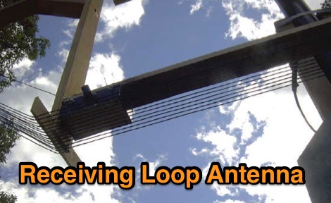 A receiving loop antenna for low frequency DX Work
 -
 Magnetic Loop antenna for 20 to 80 meters band using home made butterfly condensator kit
 -
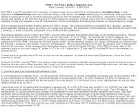
 by Jim Stafford, W4QO appeared in QRP Quarterly, Fall, 2006
 -
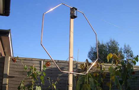
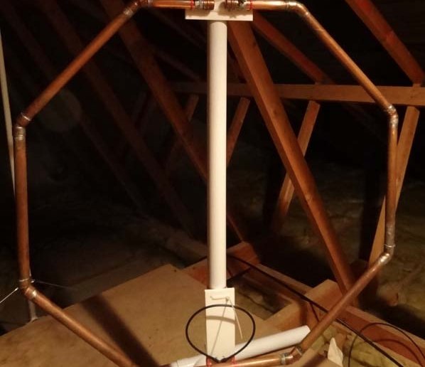 Octagonal magentic loop antennas that work from 20 to 10 meters with pictures and efficiency reports by G1KEA
 -
 Article from 73 Amateur Radio Today about experimenting on ferrite loops transmitting loop antennas for 80 and 160 meters bands.
 -
 Simple 6 Metre DX Antenna based on an article by LB Cebick in QST May 2002 on a Quad Turnstile antenna. This antenna is basically two full wave loops mounted at right angles fed 90 degrees out of phase to produce an omni-directional horizontally polarized pattern
 -
 A dual band delta loop antenna resonating on 30 and 40 meters band using a single wire for the top slopers on both 30 and 40 meters and does not need any balun
 -
 A few pictures of an homebrew magnetic loop RTX antenna project, working from 30 to 12 meters with excellent results
 -
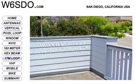 An almost invisible wire antenna for the 17 meters band
 -

-
 A 2 elements delta loop antenna for 14 MHz with a MMana simulation file, dimensions, pictures of this aluminium tube based delta loop antenna, and matching system details.
 -
 Operating a ham station often involves encountering radio frequency interference (RFI), RF feedback, or RF burns, which are frequently misattributed to poor equipment grounding. This resource meticulously dissects these assumptions, asserting that RF grounds on the operating desk often merely mask more significant system flaws. It identifies five primary causes for RF problems, including antenna system design flaws, proximity of the antenna to the operating position, DC power supply ground loops, equipment design defects, and poorly installed connectors or defective cables. The content emphasizes that issues like "hot cabinets" or changes in SWR when connecting a ground indicate substantial RF flowing over wiring or cabinets, a phenomenon known as common-mode current. The article provides detailed explanations of common-mode current generation, particularly from single-wire fed antennas like longwires, random wires, and OCF dipoles, which inherently present high levels of RF in the shack. It also illustrates how vertical antennas, lacking a perfect ground system, can excite feed lines with significant common-mode current. Through simulations, the author demonstrates how a dipole without a proper _balun_ can cause RF problems at the operating desk, showing current patterns and voltage distributions on feed line shields. The discussion extends to the proper application of _RF isolators_ and _ferrite beads_, clarifying their role in modifying common-mode impedance on cable shields and cautioning against their use as a band-aid for fundamental system defects. The resource advocates for correcting the actual source of RF problems, such as antenna system issues or poor connector mounting, rather than relying on internal shack grounding or isolators. It highlights that properly functioning two-conductor feed lines, like coaxial or open-wire lines, should result in minimal RF levels at the operating position, even without a desk RF ground. The author shares personal experience, noting that his stations since the late 1970s have operated without RF grounds at the desks, relying instead on proper antenna system design and feed line integrity.
 -
 US amateur radio antenna manufacturer. Produce baluns, delta loops, dipoles, ocf antennas and more
 -
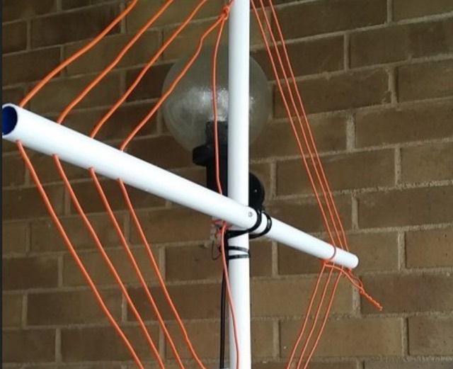
 Such kind of omnidirectional antenna gives the possibility to be QRV with horizontal polarisation, as commonly used for the CW and SSB section of the 2m band. This actual design shows a 1.3:1 bandwidth of about 150kHz, centered to 144.200MHz.
 -
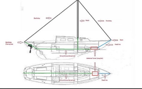 A Simple Delta Loop Antenna for Smaller Vessels
 -
 A shielded broadband (~200 MHz) active loop antenna offers more quiet and relatively less interference reception.