Search results
Query: transmission 1
Links: 280 | Categories: 15
Categories
- DX Resources > Beacons > 10 GHz Beacons
- Software > ACARS
- Software > Audio Recorders
- Software > Digital Amateur Television
- Software > DX Cluster
- Operating Modes > ESSB
- Antennas > Feed Lines
- Operating Modes > NBEMS
- Radio Scanning
- Software > RF Design
- Operating Modes > Robust Packet
- Technical Reference > Standing Wave Ratio
- Operating Modes > System Fusion
- Antennas > Theory
- Software > Voice Keyer
-
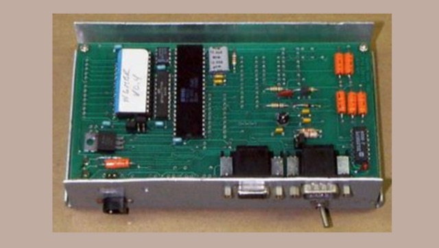 When it is time for you to hide a Hidden Transmitter there are several ways to control the transmission timing and audio of the transmitter.The most basic of these is of course the manual method of hiding in the bushes with your trusty HT and talking on and off for several hours.
 -
 An FT-817 ceased transmission on the VHF 2m band, despite the other HF, UHF, and 50 MHz bands operating correctly. Suspecting an excess of input signal during FT-8 mode transmission, they conducted measurements with an oscilloscope, revealing a burnt-out PIN diode, identified as D3003, type HSU277, on the PA unit board. Following the replacement of this surface-mounted diode, their FT-817 resumed operation on the 144 MHz band.
 -
 The article explores the concepts of return loss, VSWR, and S11 within the context of microwave engineering, highlighting the confusion arising from their definitions. It clarifies that these parameters, while seemingly distinct, fundamentally describe the same phenomenon related to wave reflection and transmission in microwave circuits. The discussion emphasizes the historical context and mathematical relationships among these terms, revealing that their interpretation can vary significantly across different engineering disciplines. Ultimately, it advocates for a pragmatic approach to using these parameters based on familiarity rather than strict definitions.
 -
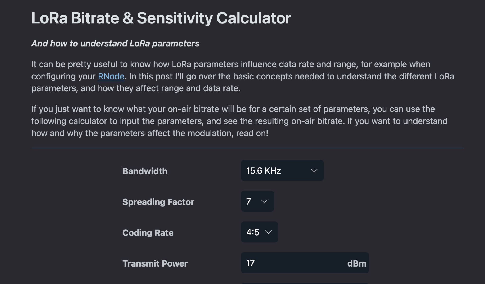 This article explains how LoRa parameters impact data rate and range when setting up a LoRa transceiver. It covers the basic concepts needed to understand different LoRa parameters and their effects on modulation. By adjusting parameters, you can achieve fast data transfers or extend transmission range. The post also offers a calculator to determine on-air bitrate based on input parameters. Understanding LoRa parameters is crucial for optimizing performance and achieving desired communication outcomes.
 -
 This article explores the powerful features of AutoEZ as an Excel application working with EZNEC antenna modeling software. The article demonstrates how variables, equations, and formulas enable versatile antenna design and automatic optimization. Through practical examples including dipoles, inverted vees, delta loops, and monopoles, the author shows techniques for achieving resonance, implementing transmission line resonators for broadbanding, and optimizing antennas across frequency ranges. The step-by-step demonstrations cover unit conversion, coordinate calculations, segmentation considerations, and SWR optimization. This practical guide illustrates how AutoEZ extends EZNEC's capabilities, making complex antenna modeling more efficient and accessible.
 -
 Amateur Television (ATV) is a ham radio technology that transmits and receives broadcast-quality video and audio. It utilizes existing standards for commercial television and can be used for various purposes including experimentation, entertainment, and public service events. ATV signals can be relayed over long distances using repeaters and are capable of transmitting live video from locations like the International Space Station. The article explores how to get started with ATV, highlighting its ease of use and suitability for beginners in ham radio. The future of ATV appears promising with advancements in digital and narrowband transmission techniques.
 -
 This page provides basic information about SWR (Standing Wave Ratio) and its importance for ham radio operators. It explains what SWR is, how to measure it, and why it is crucial to have a good SWR reading. The content covers the impact of SWR on antenna efficiency, power transmission, and potential interference issues. It clarifies common misconceptions like the impact of coax length on SWR. Suitable for hams looking to optimize their radio setup and avoid performance issues due to SWR issues.
 -
 This excel workbook addresses the issue of power loss in transmission lines with complex characteristic impedance ZoZo​. It illustrates the discrepancy between actual loss (0.35 dB) and matched line loss (0.6 dB) using a simplified example, highlighting potential software tool limitations. The RF Feedline Power-Loss Calculator provides accurate end-to-end loss assessments for both microwave and RF applications. This tool is suitable for engineers and students and is compatible with Windows versions of Excel 2016 or later, though it is not compatible with Macintosh systems.
 -
 This comprehensive article dispels common misconceptions about Standing Wave Ratio (SWR) in amateur radio. The author explains that SWR is not an antenna property but a measure of the entire antenna system, representing the mismatch between transmission line and load impedance. Contrary to popular belief, modest SWR values (under 3:1) typically cause minimal power loss in HF applications. The article demonstrates mathematically why obsession with achieving 1:1 SWR is often unnecessary, explains when SWR matters more (QRO, QRP, VHF/UHF), and explores effective matching techniques including proper ATU placement and quarter-wavelength transformers.
 -
 This page by ARCTICPEAK provides a calculator for determining ERP and EIRP (Effective radiated power and effective isotropic radiated power). The tool is designed to help hams calculate and understand the power radiated by their radio equipment. The content is useful for ham radio operators who want to optimize their transmission power and comply with regulations. LA8OKA Martin has created this resource to assist hams in accurately measuring their radio signals.
 -
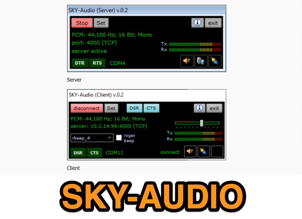 SKY Audio is a duplex remote audio software for Windows, allowing two-way audio transmission between devices. Users can send and receive audio, as well as engage in PTT functionality. The program offers low audio latency and the ability to configure connection settings. The freeware software can be downloaded from the provided link.
 -
 The article discusses the construction of a UHF band-stop stub filter to protect an APRS receiver from potential damage during a balloon launch. The author, who communicates using a 441 MHz transmitter, needed to ensure that the RTL-SDR dongle receiving at 144 MHz wouldn't be damaged by the transmissions. The solution involved creating a quarter-wavelength open stub filter using coaxial cable, which attenuates the 441 MHz signal while allowing the 144 MHz signal to pass through. The filter's design is based on the principles of constructive and destructive interference, with careful measurement and trimming to achieve the desired frequency response. The final filter provided 34.8 dB of insertion loss at 441 MHz and minimal loss at 144 MHz, effectively protecting the receiver.
 -
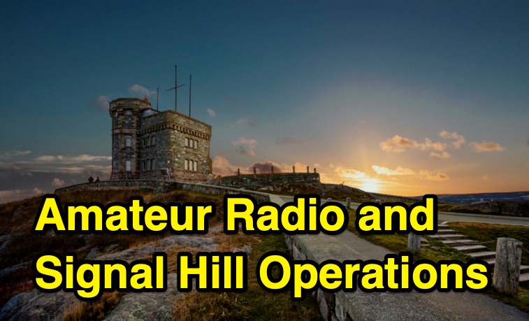 Examines the historical context of amateur radio, specifically focusing on Guglielmo Marconi's pioneering wireless transatlantic signal reception at Signal Hill, Newfoundland, in 1901. It describes the operation of a contemporary remote radio station at Signal Hill, utilizing the special event call sign _VD1M_ issued by Innovation, Science and Economic Development Canada. The content recounts a specific contact from Signal Hill, reporting a signal strength of 5 by 9 to a station in Sarnia, Ontario, which received the signal at 3 by 3. The narrative also introduces the concept of 'Marconi chasers' who endeavor to replicate historical transmission methods. Further, the resource discusses general amateur radio operating procedures, the evolution of the hobby, and its critical role in emergency communications, citing examples from hurricanes _Irma_ and _Maria_ in 2017 and the conflict in Ukraine in 2022.
 -
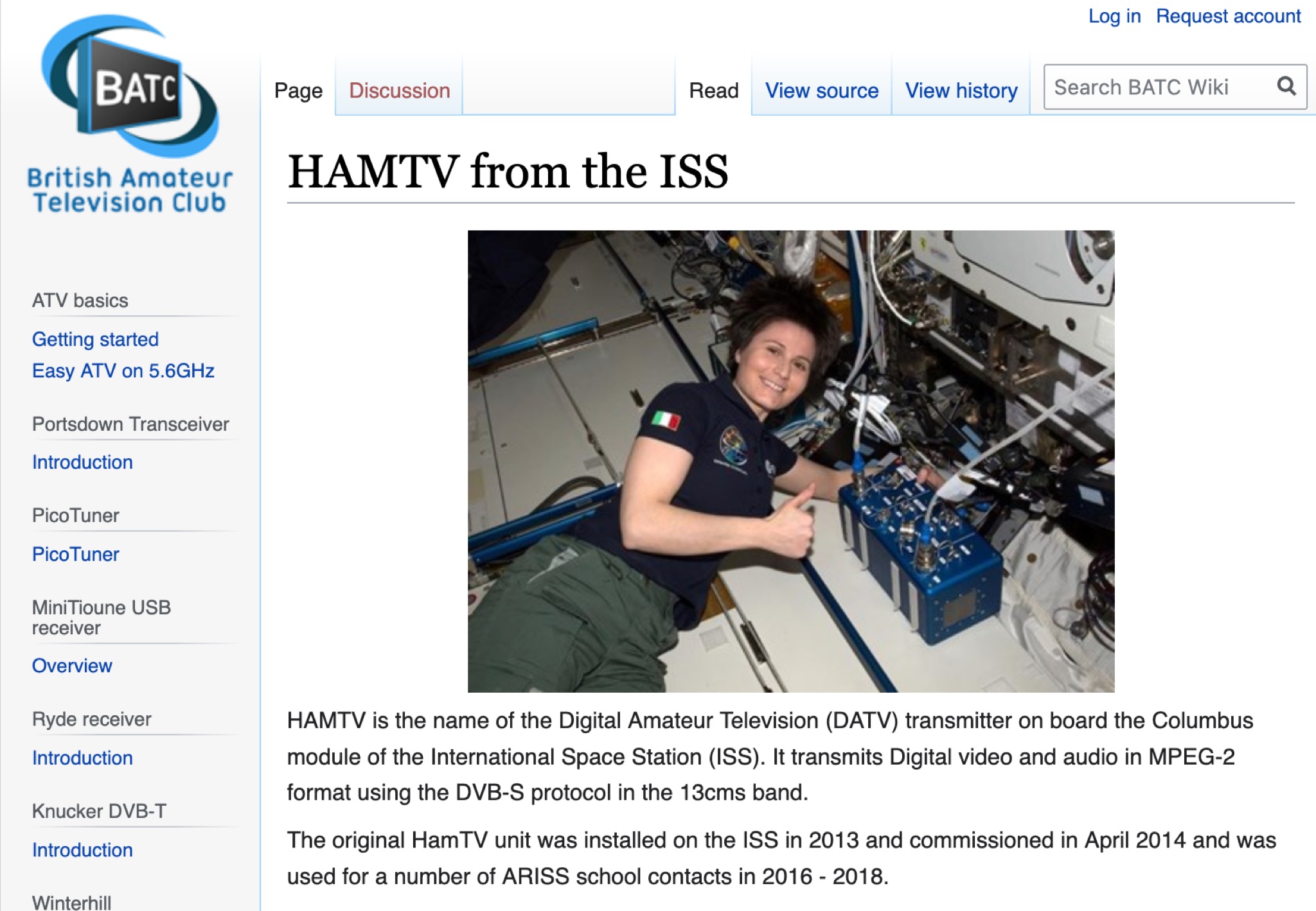 Learn about the HAMTV Digital Amateur Television (DATV) transmitter on the International Space Station (ISS), transmitting video and audio in MPEG-2 format using the DVB-S protocol. Discover its history, installations, failures, and repairs, as well as the current status and live video feed. Explore the technical details and challenges of the HAMTV transmitter, including power output, polarization, and antenna location. Find recordings of previous transmissions and understand the potential signal reflections caused by various ISS components. Stay updated on the latest developments and activities related to HAMTV from the ISS.
 -
 Testing IdeeTron Lorank8 for LoRaWAN with ham radio transmissions. Assessing compatibility, interference, and planning permanent setup. Follow the experimentation and integration into the Almelo Community page
 -
 After years of reliable performance, a 26-year-old Icom 706MK2G exhibited an unusual deviation during FM transmission, with the actual frequency being 10kHz off from the displayed frequency. Additionally, the power meter showed a sharp dip during transmission. Upon investigation, it was discovered that the FM VCO voltage adjust variable had become dirty and sluggish over time. By adjusting the variable capacitor and cleaning it with switch cleaner, the issue was resolved, restoring stable power output and accurate frequency transmission.
 -
 This page by Arctic Peak provides a detailed explanation on how to use quarter-wave transmission lines as impedance transformers in ham radio antenna work. It explains how to match impedance values by connecting them with a λ/4 transmission line. The page also offers guidance on constructing your own transmission lines with specific impedance requirements, along with a calculator to determine the quarter wave length based on velocity factor and frequency. Useful for hams looking to optimize antenna performance and match transmission line impedance effectively.
 -
 This page provides a detailed guide on the J-pole antenna, an end-fed half-wave antenna matched to the feedline by a quarter-wave transmission line stub. It covers the characteristics, construction materials, feeding options, and mounting considerations for optimal performance. The information is useful for hams or amateur radio operators looking to build and set up a J-pole antenna for improved transmission and reception.
 -
 The article describes ongoing issues with a new TS590s transceiver, including intermittent reception and transmission failures. After a repair diagnosed as a "Control Unit interruption," the problem persisted. The author discovered the cause was a poorly crimped CN601 connector on the Control Unit board, leading to signal loss when moved. Soldering the connector resolved the issue. Similar problems reported by other users suggest a potential defect in the cables, pointing to a possible manufacturing issue.
 -
 The Gemini Amplifier Remote Control software operates on Windows 7 and above, facilitating remote management of the Gemini HF-1K and DX-1200 amplifiers. Users connect via Ethernet, configuring the amplifier's IP address through the front panel. The software allows seamless band and antenna selection, saving settings for each band without requiring transmission. Integration with _OmniRig_ from Afreet Software, Inc. enables automatic band adjustments based on the radio's frequency changes. Users can configure serial or virtual serial connections, with tracking options accessible through the ribbon bar. The software supports speech functionality, enhancing accessibility for operators. Firmware updates, such as version 2.5Ee, introduce features like background datalogging and power output control, uploaded via FTP. Version 1.2.0 allows users to offload internal parameter data for support purposes. The firmware upload process requires the amplifier's IP address and port 21, taking approximately 90 seconds. Users are encouraged to upgrade to the latest firmware for improved performance and remote diagnostics.
 -
 An Arduino-based interface provides a remote tuner call command for Icom **IC7700** and **IC7800** transceivers, addressing the lack of a built-in function for external tuners such as the MFJ 998RT. This setup initiates a low-power transmit signal, typically 15 watts, allowing the remote autotuner to perform its matching sequence. The article details the required CI-V line communication and modifications to existing Arduino code, specifically referencing contributions from Jean-Jacques ON7EQ for improved Icom interrogation routines. The system involves a sequence of steps: storing the transceiver's current mode and power, disabling the internal autotuner, activating a control relay to interrupt the amplifier line, switching to RTTY mode at low power, and initiating transmit. The transmit duration is manually controlled by the operator, observing the SWR meter until a low SWR is achieved, then a second button press stops the transmission. A built-in 4-second transmit limit provides a safety measure. After tuning, the routine restores the original mode and power settings, re-enables the internal autotuner, and performs a brief 2-second RTTY transmission for internal tuner adjustment. The circuit diagram includes a Panasonic form 2 relay for amp control and emphasizes critical delays in the Arduino code for stable operation at 9600 baud CI-V communication. Compatibility with logging software like DXLab, N1MM, and N3FJP is noted, with specific interrogation time settings required to avoid conflicts.
 -
 Tracing the foundational work of Guglielmo Marconi, this article details his early laboratory experiments in 1895, where he successfully transmitted wireless signals over 1.5 miles. It highlights his 1896 patent for a wireless telegraphy system in England and subsequent demonstrations, including signal transmissions up to 6.4 km (4 miles) on Salisbury Plain and nearly 14.5 km (9 miles) across the Bristol Channel. Marconi's work built upon the mathematical theories of _James Clerk Maxwell_ and the experimental results of _Heinrich Hertz_, proving the practical feasibility of radio communication. The resource further chronicles the formation of The Wireless Telegraph & Signal Company Limited in 1897 and Marconi's relentless efforts to popularize radiotelegraphy. A significant milestone was the 1901 transatlantic reception of the Morse code letter "S" from Poldhu, Cornwall, at St. John's, Newfoundland, using a kite-supported wire antenna, defying contemporary mathematical predictions about Earth's curvature limiting range. This achievement underscored the global potential of radio. The article also touches upon Marconi's later discoveries, such as the "daytime effect" concerning atmospheric reflection of radio waves, and his 1902 patent for a magnetic detector, which became a standard wireless receiver. His contributions earned him a Nobel Prize in 1909.
 -
 This page provides a calculator to determine the total line loss and additional line loss in your transmission line based on the level of SWR. It helps hams understand the impact of high SWR on transmission line losses. The calculator allows users to input their SWR level and get accurate calculations of total losses. This tool is useful for ham radio operators looking to optimize their transmission setups and improve overall efficiency.
 -
 This study analyzes the antenna pattern of the Utah Amateur Radio Club's 146.760 MHz repeater following antenna relocation in 1997. Noting degraded transmission toward the north, a customized signal mapping system using a Yaesu FT-817, GPS, and software was developed to log real-time signal data. Calibration techniques extended the radio's signal range, enabling precise field measurements. The method allowed continuous signal strength monitoring while driving, revealing anomalies in coverage likely due to tower modifications. Findings helped assess and visualize the antenna’s actual radiation pattern and highlighted environmental impact on signal distribution.
 -
 Early 20th-century transatlantic wireless communication efforts involved distinct technical approaches by Reginald Fessenden and Guglielmo Marconi. Marconi's systems, operational until approximately 1912, primarily utilized _spark technology_ for wireless telegraphy, facilitating Morse code communication between ships and across oceans. His Poldhu station in December 1901 radiated signals in the MF band around 850 kHz, later evolving to 272 kHz in October 1902, and eventually 45 kHz by late 1907 with increasingly larger antenna structures like the pyramidal monopole and capacitive top-loaded arrays. Fessenden, conversely, focused on _continuous wave transmission_ for wireless telephony, recognizing its necessity for speech. His transatlantic experiments in 1906 employed synchronous rotary-spark-gap transmitters and 420-foot umbrella top-loaded antennas at Brant Rock, MA, and Machrihanish, Scotland, tuned to approximately 80 kHz. Fessenden later utilized the _Alexanderson HF alternator_ at 75 kHz by late 1906 for pure CW transmission, integrating a carbon microphone for amplitude modulation. Receiver technology also differed, with Marconi initially relying on untuned coherer-type detectors, later developing the magnetic detector in 1902, while Fessenden's CW approach necessitated more advanced detection methods.
 -
 Learn about Amateur Television (ATV) on the 23 cm band (1240-1300 MHz) in this article from the September and October 2000 issue of Mégahertz magazine. Discover how ATV adds a new dimension to QSOs by allowing hams to visit stations, transmit real reports on antenna installations, follow signal paths on camera, and have simultaneous sound transmission. Explore the world of ATV experimentation, comparison, and innovation, made easier by existing equipment in many ham radio operators' homes. Find out about the ATV bands, bandwidth requirements, and the 23 cm band as a starting point for ATV activities.
 -
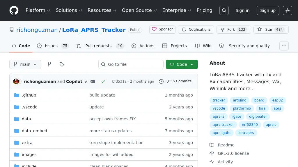 Demonstrates a LoRa APRS Tracker project featuring a comprehensive menu system for message management, weather requests, and monitoring nearby trackers. The device supports adjustable display eco mode and screen brightness, optimizing power consumption by dynamically changing processor speed from 240MHz to 80MHz. GPS beacons are encoded for efficient RF transmission, and an OLED screen displays altitude, speed, course, _BME280_ weather data, or new message counts, along with recently heard stations. Bluetooth connectivity enables operation as a TNC with Android (APRSdroid) or iPhone (APRS.fi app), providing LED and sound notifications for transmissions and received messages. The integrated BME280 module facilitates weather data display and transmission, with Winlink mail support via _APRSLink_. The tracker can switch between **three major LoRa APRS frequencies** worldwide, offering versatile global operation.
 -
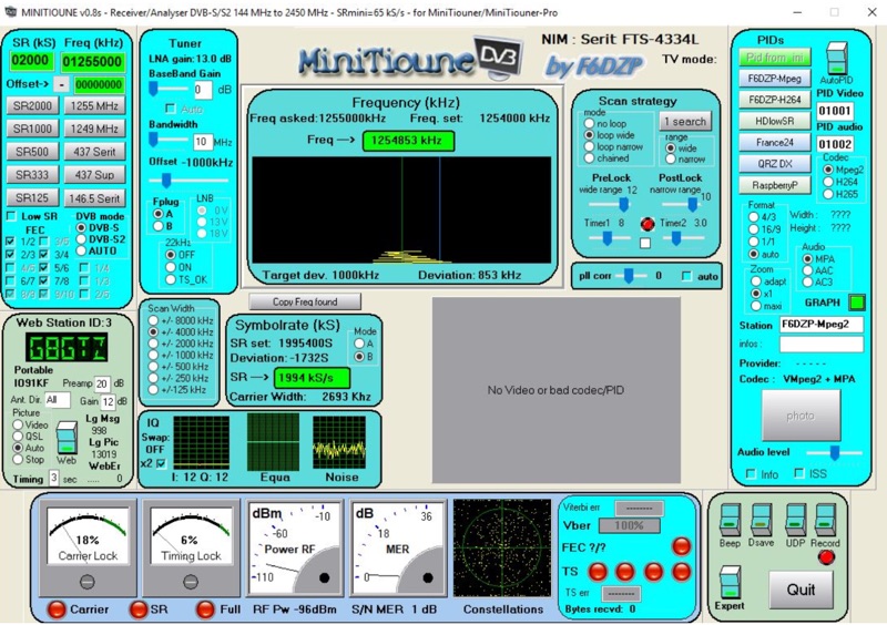 Receiving Digital Amateur Television (DATV) signals requires specialized software to interface with hardware tuners and decode the video stream. The _MiniTioune_ software, developed by F6DZP, serves this purpose, providing a Windows-based application for DVB-S and DVB-S2 reception and analysis. It is designed to work in conjunction with _MiniTiouner_ hardware, enabling hams to monitor DATV transmissions, including those from the QO-100 geostationary satellite. The resource outlines the initial setup process, including connecting the MiniTiouner hardware via a high-quality USB2 mini cable and running diagnostic test software. It details how to configure essential parameters such as symbol rate (SR), FEC rate, and DVB mode for various signal sources, from domestic satellite dishes to local DATV transmitters. Troubleshooting steps for common issues like "no video displayed" are also provided, often pointing to corrupted software filters or incorrect _Auto PID_ settings. Advanced features like the Web monitor for remote signal reporting and integration with _VLC_ media player for more tolerant decoding of non-DVB compliant signals are covered. The document also references a comprehensive user guide by W6HHC for the _MiniTiouner-Express_ system, which utilizes the same software, offering further in-depth assistance for operators.
 -
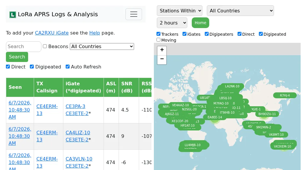 Demonstrates the operational status and reach of the LoRa APRS infrastructure, providing a live mapping and logging service for network participants. Users can verify network coverage, monitor _iGates_, and track mobile stations, observing messages and real-time network activity. The platform offers insights into station locations and data flow within the LoRa APRS system, which is crucial for understanding the performance of LoRa technology in Automatic Packet Reporting System applications. This utility helps amateur radio operators understand where transmissions are being received and processed by iGates, and how mobile units are moving within the network. The site's analysis tools provide RF performance monitoring and metrics, enabling users to assess network efficiency and identify areas for improvement. For example, operators can see how many packets are received by specific iGates, or track the path of a mobile station over a **100 km** range, offering practical insights into signal propagation and network reliability for _packet radio_ enthusiasts.
 -
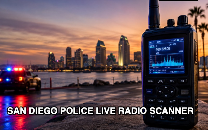 Monitoring public safety communications, particularly fire department dispatch, presents a unique challenge as agencies increasingly move towards encrypted systems. This Broadcastify feed, originating from a _BCD396XT_ scanner situated in northern San Diego City, provides real-time audio for the San Diego City Fire Department. While it previously included police dispatch, those transmissions are now fully encrypted, a common trend impacting scanner enthusiasts and emergency services observers alike. The setup utilizes a Windows server running _Freescan_ and _RemoteFS_ for remote control, ensuring consistent operation and clear audio via a ground loop isolator. With a peak of 8,785 listeners in the last 24 hours, the feed demonstrates significant interest in local emergency traffic. Alpha tags, indicating the current channel, are generally available for premium users, enhancing situational awareness for listeners. Feed archives are maintained in 30-minute segments, allowing for review of past incidents and operational patterns, a valuable feature for those studying emergency response or simply keeping informed about local events.