Search results
Query: 100 kHz
Links: 34 | Categories: 0
-
 Presents the KE4UYP linear-loaded vertical antenna design, which introduces very little loss on 80 or 160 meters, achieving an overall radiation efficiency of 80% to 85%. This design addresses common pitfalls of traditional base-fed verticals by placing the majority of the current at the top of the antenna, eliminating the heavy reliance on extensive ground radial systems. The author's initial 10-meter model, only three feet tall, yielded 5/9 signal reports to Anchorage, AK, and Europe, confirming its effectiveness. The antenna incorporates both vertically and horizontally polarized radiators, with a 1/4 wavelength horizontal counterpoise located at the feed-point, near the top, to create an almost totally omnidirectional pattern with high wave angle horizontally polarized radiation. This dual polarization ensures even illumination across all take-off angles, making it effective for both local contacts and **DXing**. The vertical element is linear loaded, adding capacitance reactance and making it longer than the horizontal element to achieve resonance and raise the feed-point impedance to 50 ohms. Fine-tuning the antenna requires careful adjustment, as tower reactance can vary. The article suggests starting with 80 feet for 80m and 170 feet for 160m for the vertical wire, then trimming for resonance. Bandwidth specifications include 300 kHz under 2:1 **SWR** on 80m and 100 kHz on 160m when suspended between trees, or 150 kHz on 80m when side-mounted on a tower.
 -
 The project details modifications to an ARK-40 QRP CW transceiver kit, specifically replacing its original thumbwheel frequency selectors with a **BASIC STAMP BS-II microcontroller** and an optical shaft encoder. The redesigned control circuitry outputs a BCD code to the ARK-40's synthesizer, enabling more convenient knob-type tuning. This modification significantly alters the user interface, moving from discrete frequency selection to continuous tuning. Operating frequency is presented on an LCD readout, offering two distinct display modes: a "bandspread dial" mode that simulates an analog dial scrolling across the display in 1 kHz increments, and a conventional digital readout with 100 Hz resolution. Pushing the main tuning knob toggles between these modes, providing both rapid band traversal and fine-tuning capabilities. The software for the BASIC Stamp is written in P-Basic, addressing the challenge of accurate analog dial simulation. Physical modifications include fabricating a custom PC Board for the STAMP, mounting it with an L-bracket to the optical encoder, and creating a new front panel. The front-mounted speaker was relocated to accommodate the new tuning knob and display, transforming the **ARK-40 transceiver** into a more user-friendly rig with its built-in CW keyer and 5 watts of power.
 -
 Control an ICOM PCR-100 and listen to the audio stream. This web controlled receiver si based in the Netherlands by PA3ANG and offer 10kHz - 1300MHz in AM, FM, FMW
 -
 The RigPix database entry provides a comprehensive technical overview of the Icom IC-746 amateur HF/VHF transceiver, detailing its operational parameters and physical characteristics. It specifies the transmit frequency ranges across 10-160 meters plus WARC bands, 50-54 MHz, and 144-146/148 MHz, alongside receive coverage from 0.03-60 MHz and 108-174 MHz. The resource outlines supported modes including AM, FM, SSB, CW, and RTTY, noting a tuning step resolution down to 1 Hz and a frequency stability of ±5 ppm. Key electrical specifications are presented, such as a 13.8 VDC power supply requirement, current drain figures for RX (1.8-2 A) and TX (Max 20 A), and RF output power ranging from 5-40 W for AM and 5-100 W for FM, SSB (PEP), and CW. The entry details the triple conversion superheterodyne receiver system, listing IF frequencies at 69.01 MHz, 9.01 MHz, and 455 KHz, along with sensitivity ratings for various modes and bands. Transmitter section specifics include modulation systems and spurious emission levels. Additional features like a built-in auto ATU, electronic keyer, simple spectrum scope, DSP, and CI-V computer control are noted. The page also lists related documents, modifications, and an extensive array of optional accessories, including various filters, microphones, and external tuners, providing a complete profile of the IC-746.
 -
 The W1TAG LF Receiving Loop is a specialized antenna project for LF reception, designed to mitigate local noise and enhance weak signal pickup on the lower frequencies. This square loop, measuring 6 feet per side, utilizes 14 turns of #12 THHN wire wound on a PVC frame, offering a robust mechanical structure. The design incorporates a series-tuned circuit with a coupling transformer, allowing for tuning from over 400 kHz down to _45 kHz_ using a switched capacitor bank. Construction details include the use of 1.5-inch PVC pipe for the frame, with specific measurements for spreaders and drilled holes for wire threading. The two 7-turn sections of wire are connected at the center, providing an option for a center tap. The loop rotates on a 1-inch steel pipe, enabling directional nulling of noise sources. The tuning unit, housed in a box clamped to the PVC, employs a 1:2 step-up transformer wound on an _FT-82-77 core_ and uses relays to switch capacitance values from 50 pF to 6400 pF, providing precise frequency adjustment. The current setup connects to the shack via 100 feet of RG-58, feeding into a W1VD-designed preamp, with plans for a balanced, shielded twisted pair cable upgrade.
 -
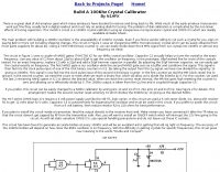 Restoring vintage amateur radio gear often presents challenges with accurate dial calibration due to the non-linear characteristics of analog tuning capacitors. This resource details the construction of a 100 kHz crystal calibrator, a crucial tool for precisely setting the frequency of older rigs lacking digital readouts. The design cleverly circumvents the scarcity and cost of 100 kHz crystals by utilizing a readily available 8 MHz microprocessor crystal, such as a _HC49U_ type, in conjunction with common _CMOS ICs_ like the 74HCT00 quad NAND gate and 74HCT393 dual 4-bit binary ripple counter. The circuit employs a two-stage frequency division process: the 8 MHz crystal oscillator output is first divided by 16 to yield 500 kHz, then further divided by 5 to achieve the desired 100 kHz output. A 5.1-volt Zener diode, _1N4733A_, regulates the power supply for the HCT series logic. The article also provides a modification to produce a 50 kHz calibrator by altering the counter reset logic. Installation involves feeding the output to the receiver front end, ensuring it's post-TR relay to prevent RF damage, and incorporating an ON/OFF switch for the 12V supply line.
 -
 Constructing a functional spectrum analyzer for the 0-100 MHz range presents a significant challenge for radio amateurs, often requiring specialized components and careful calibration. This project details a homebrew spectrum analyzer design utilizing common integrated circuits like the _SA605D_ FM receiver IC and _MAR-6_ MMIC amplifiers, aiming for a cost-effective solution. The design incorporates a low-pass filter, RF amplification, a voltage-controlled oscillator (VCO) for downconversion, and multiple IF stages at 150 MHz and 10.7 MHz, with a resolution bandwidth (RBW) of 15 kHz. Critical components such as the _SBL-1_ mixer and varicap diodes are specified, alongside instructions for winding inductors and tuning filters. The analyzer's performance is discussed in terms of input level limitations, specifically the 1dB-compression point and third-order intercept point, to ensure accurate measurements and prevent component damage. The _SA605D_'s logarithmic Received Signal Strength Indicator (RSSI) output serves as the detector, driving the Y-input of an oscilloscope, while a _TL084_ op-amp generates the sweep signal for the X-input. Potential enhancements include adding a step attenuator, improving front-end filtering, and implementing switchable IF filters for variable RBW, allowing for greater versatility in analyzing RF signals.
 -
 This article describes a low-cost vector network analyzer that operates from 200 kHz to 100 MHz, and connects to a personal computer using a USB 1.1 interface By Tom McDermott, N5EG, and Karl Ireland
 -
 Presents a QRP AM/CW transmitter project specifically designed for the 10-meter band, utilizing a crystal oscillator and a collector-modulated AM oscillator. The design employs a 2N2219(A) transistor in a Colpitts configuration, generating 100 to 350 mW of RF output power depending on the 9-18 Volt supply voltage and modulation depth. Frequency stability is maintained by a 28 MHz crystal, with fine-tuning possible via a Ct1 trimmer capacitor for approximately 1 kHz adjustment. The resource details the RF oscillator stage, implemented with a 2N2219 NPN transistor, emphasizing frequency stability and low power dissipation. It also covers the amplitude modulation stage, managed by a 2N2905 PNP transistor, which impresses audio information onto the carrier. Selective components (C3, C4, C7, C5) enhance voice frequencies within a +/- 5 kHz bandwidth, and modulation depth is controlled by R2 and R3. The project includes a 3-element L-type narrow bandpass filter (Ct3, L3, C10) to suppress harmonics and ensure a clean output signal. The project provides a complete schematic diagram, a comprehensive parts list including specific capacitor, resistor, and inductor values, and construction notes for the coils (L1, L2, L3). It also offers practical advice on enclosure requirements, suggesting an all-metal case or a PVC box with graphite paint for RF shielding. Operational parameters such as current draw (27mA@9V to 45mA@16V) and input impedance (50 Ohms) are specified, alongside guidance on antenna matching and the importance of a valid amateur radio license for 10-meter band operation.
 -
 This project details the construction of a **full-sized 40-meter vertical antenna**, born from a renewed interest in 7 MHz operation and a desire for improved effectiveness over simple dipoles. The author, K5DKZ, initially focused on VHF experimentation, which provided an inventory of aluminum tubing and fiberglass spreaders for this endeavor. Before this vertical, K5DKZ utilized an 80/40 meter inverted-vee trap dipole and a 40-meter broadband dipole, but now primarily uses a pair of full-sized, phased, quarter-wave verticals spaced 35 feet apart for serious 40-meter work. The construction involves a base-heavy design for stability, using a 44.5-inch section of 1-1/4 inch steel TV mast driven into 1-3/8 inch aluminum tubing, insulated by a 105-inch section of Schedule 40 PVC pipe. The assembly reaches 31 feet, close to the 32 feet required for a quarter-wavelength on 40 meters, with fine-tuning achieved by winding wire onto a fiberglass spreader. The design is explicitly presented as a foundation for a two-element 40-meter Yagi beam, outlining modifications like substituting aluminum for steel in the base and using an inductive hairpin match for the driven element. The article also discusses tuning considerations for a large 40-meter beam, noting the 100 to 200 kHz upward frequency shift when raised, and suggesting methods for installation on a tower. The author emphasizes the cost-effectiveness and good performance of the monopole approach, especially when multiple verticals are needed.
 -
 Over 100 amateur radio beacon audio files are presented, offering a direct auditory experience of propagation conditions across a wide spectrum of frequencies, from 1.8 MHz to 47 GHz. These recordings, primarily captured by IW3FZQ and IK3NWX, document signals from beacons such as DK0WCY, IY4M, GB3RAL, and S55ZRS, providing a valuable resource for **propagation study** and **beacon monitoring**. Each entry in the list specifies the beacon's callsign, its operating frequency in kHz, and the recording operator. This compilation includes signals from beacons located in various grid squares like JN55VF, JO44VQ, and IO91IN, illustrating diverse geographical origins. The frequencies covered span the 160m, 80m, 40m, 30m, 20m, 17m, 15m, 12m, 10m, 6m, 4m, 2m, 70cm, 23cm, 6cm, 3cm, 1.2cm, and 6mm amateur bands. Users can listen to these recordings to identify characteristic beacon tones and observe signal strength variations. The resource also invites other radio amateurs to contribute their own beacon audio files, fostering a collaborative archive of propagation data. The last update to this collection was on March 24, 2009, indicating a historical snapshot of beacon activity. Accessing the files requires the Real Player software.
 -
 A 200 kHz bandwidth digital transmission system for image transfer in the Amateur Service is under development, specifically targeting VHF allocations. John B. Stephensen, KD6OZH, leads this project under an FCC Special Temporary Authority (STA) valid until September 10, 2006, authorizing emissions up to 200 kHz bandwidth in the 50.3-50.8 MHz segment. Current regulations typically limit bandwidths to 20 kHz on VHF amateur bands, making this STA crucial for testing wideband digital modes. The modem, a modified **OFDM** (Orthogonal Frequency Division Multiplexed) unit, was initially tested on the 70-cm band. It splits a high-rate data stream into multiple low-rate subcarriers to mitigate multipath echoes. The system uses a DCP-1 card with a Xilinx XC3S400 FPGA and Oki Semiconductor ML67Q5003 microcontroller. The transmitter, located at 36d 46m 30s N, 119d 46m 22s W, generates 150 WPEP into an 8 dBi gain vertical antenna, while the mobile receiver uses a Ham-stick. Three data formats for 50, 100, and 200 kHz channels are being tested, with encoded data rates of 96, 192, and 384 kbps. Verilog code for the VHF OFDM modem is 95% simulated, with modifications from the UHF version including increased filter coefficient precision and a change from Ungerboeck **TCM** to BICM for improved performance over fading paths. Final tests will involve one-way over-the-air measurements of bit error rates and coverage area.
 -
 Valcom Guelph specializes in the design and manufacturing of a full range of MF Beacon 100 KHz - 600 KHz, AM Broadcasting 540 - 1700 KHz, HF 1.8 - 30 MHz, VHF 30 - 300 MHz and UHF 300 - 1,200 MHz and SHF up to 6 GHz antennas based in Canada
 -
 Covers 10m 12m 15m 17m 20m 30m 40m and 100 KHz on 80m, & WARC Eham Reviews
 -
 137 kHz propagation analysis details ground wave and sky wave mechanisms, drawing heavily from **CCIR Rec. 368-6** for ground wave field strength predictions and **CCIR Rep. 265-7** for sky wave modeling. The resource presents field strength values for 1 W ERP at varying distances, considering ground conductivity and permittivity for ground wave, and ionospheric height (70km daytime, 90km nighttime) for sky wave. Key factors like ionospheric focusing (factor "D"), reflection coefficient ("RC"), and antenna ground pattern factors ("Ft", "Fr") are quantified for 137 kHz, enabling calculation of sky wave field strength. Practical coverage ranges are derived for 137 kHz, showing useful ground wave coverage up to 1600 km over seawater and 1100 km over average ground, assuming a -9 dBuV/m noise floor. Sky wave coverage extends beyond 2200 km during night-time and winter daytime, but is negligible during summer daytime at solar minimum. The document also compares ground wave and sky wave strengths, identifying crossover distances at 550 km (night-time), 750 km (winter daytime), and 1250 km (summer daytime), where interference fading can occur. Adjustments for solar maximum conditions are provided, indicating 2-11 dB higher sky wave values depending on distance and season.
 -
 The Lakeshore Repeater Association (KR9RK) operates a **VHF** 2-meter repeater on 147.270 MHz, utilizing a +600 kHz offset and a 100 Hz PL tone, serving the Raymond, Wisconsin area. The organization provides access to monthly newsletters, with recent editions including March 2026, February 2026, and January 2026, detailing club activities and operational updates. A Google Docs link is provided for newsletters with functional embedded links, addressing issues with PDF versions. The association's Megacycle Group is actively constructing a **DX Contest** level HF network, designed for remote accessibility. This initiative aims to provide members with a competitive edge in global DX hunts by enabling worldwide access to the station's radios. Additionally, the Lakeshore Radio Association is commemorating its 50th anniversary with a special event station, K5O, inviting all members to participate in on-air operations.
 -
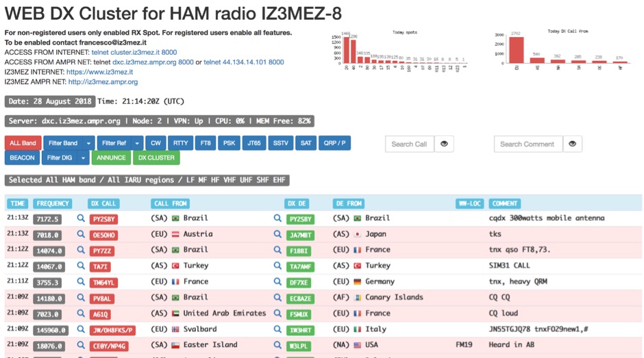 The IZ3MEZ Web DX Cluster presents real-time amateur radio DX spots across 20 distinct frequency bands, spanning from **LF (2190m)** at 135.7 kHz up to **SHF (QO-100)** at 10499 MHz. It displays the DX callsign, frequency, DXCC entity, spotter callsign, and spotter DXCC entity, along with any accompanying comments. The cluster also lists various operating modes such as CW, RTTY, FT8, FT4, FT2, PSK, and SSTV, and supports special operating activities like QRP/P and specific award programs including IOTA, POTA, SOTA, WCA, and JOTA. The cluster's interface provides a dynamic feed of the latest 50 spots, continuously updated with precise timestamps. It offers direct **Telnet protocol** access for users preferring a command-line interface, with configuration instructions provided. The resource also integrates with other spotting networks like RBN and PSK Reporter, enhancing its utility for DXers and contesters seeking propagation information and activity monitoring across a broad spectrum of amateur radio frequencies.
 -
 Fifty-three digital modes, including PSK31, RTTY, and JT65, are explored in this resource, providing detailed descriptions of their underlying technologies and typical use cases. It covers error correction methods like ARQ in PACTOR and FEC in JT65, alongside modulation schemes such as FSK and PSK. The content highlights the evolution of digital communication from traditional TNC-based systems to modern sound card implementations, emphasizing the role of personal computers in advancing these modes. Specific modes like AMTOR, PACTOR, and G-TOR are discussed, noting their baud rates and error correction capabilities. For instance, AMTOR operates at 100 baud, while PACTOR offers 200 baud with Huffman compression. The article also delves into newer modes like MFSK16, which uses 16 tones and continuous Forward Error Correction, and Olivia, capable of decoding signals 10-14 dB below the noise floor. Each mode's bandwidth, speed, and resilience to propagation challenges are examined, such as MT63's 1 KHz bandwidth and 100 WPM rate, or Hellschreiber's 75 Hz bandwidth and 35 WPM text rate. The resource also lists predominant USA HF digital frequencies for bands like 160, 80, and 40 meters, specifying segments for PSK31, RTTY, SSTV, and Packet. It includes links to freeware and shareware sound card software such as Digipan, FLDigi, and MixW, enabling amateurs to experiment with these modes.
 -
 The 2200-meter band (135.7-137.8 kHz) presents unique challenges for amateur radio operators due to its narrow 2.1 kHz bandwidth, low signal levels, and high noise. W1TAG explores various transmission modes suited for this demanding environment, highlighting that traditional voice modes like SSB and AM are impractical. Plain old CW serves as the baseline, demonstrating effectiveness across different modes, though signal-to-noise ratio (SNR) significantly limits practical speeds. The article notes that reducing CW speed below 5 WPM can improve copy, especially with computer-aided spectrum analysis software capable of decoding signals too weak for human ear reception. QRSS, or "CW sent slowly enough that speeds are best expressed in seconds per dot," is a key mode for LF work, with examples ranging from 3 seconds/dot to extreme 240 seconds/dot transmissions. _Argo_ by I2PHD is mentioned as a simple program for QRSS, enabling reception of signals like BRO, a Part 15 beacon, at a distance of **1100 miles**. Other modes discussed include Dual Frequency CW (DFCW), which uses frequency shifts to distinguish dots and dashes, and Binary Phase Shift Keying (BPSK), a phase modulation technique employing 0 to 180-degree phase flips. WOLF (Weak-signal Operation on Low Frequency), a specialized BPSK form by KK7KA, encodes 15-character messages into 960-bit packages, taking 96 seconds to transmit, and has demonstrated successful reception over **672 seconds** for a message from a 1-watt beacon. Further modes include PSK, FSK variations like JASON and MSK, and graphical modes such as Hellschreiber and Chirped Hell. The article concludes with a practical chart comparing the time required to send a simple message like "WD2XES FN42CH " across these diverse LF modes, offering valuable insights for operators planning contacts on the low bands.
 -
 Details the Big Thunder Amateur Radio Club (BTARC), a long-standing amateur radio organization based in Boone County, Illinois, established in 1962. It covers the club's mission to enhance the skills of local hams, promote radio knowledge, and foster social interaction among operators. The resource outlines BTARC's commitment to community service, including emergency communications support through RACES, and its active participation in events like Field Day, fox hunts, and public service communications for local races. Explains the club's history, including the establishment of its first repeater in the 1970s by members WD9JGH, Mike George, K9ORU, and Claude Horsman, WB9PMM, using a VHF Engineering kit and a Sinclair duplexer. It provides specifications for two club-maintained FM repeaters: a 2-meter repeater on 147.375 MHz (+600 KHz shift, 100.0 Hz PL tone) and a 70-cm repeater on 442.825 MHz (+5 MHz shift, 114.8 Hz PL tone). The club hosts a weekly 2-meter net on Sundays at 7:00 PM local time and holds monthly meetings on the second Thursday at the Spring Township Building in Belvidere, IL.
 -
 The ZS1J/B beacon operates on 28.2025 MHz with 5 Watts output to a half-wave, end-fed vertical antenna, initially installed in 1977 as ZS5VHF near Durban. The 10-meter transmitter is a modified 23-channel CB radio, and the identification keyer uses a diode matrix unit with TTL ICs from the same era. After relocation to Plettenberg Bay in 1993, the beacon has been in continuous service, with additional QRP transmitters later installed for other bands. In 1994, a single-transistor, 80-meter, 0.5-watt QRP transmitter with a half-wave dipole was added on 3586 kHz, followed by a 160-meter, 0.5-watt unit on 1817 kHz. A 30-meter, 0.5-watt transmitter was installed in 1996, operating on 10.124 MHz. In 2002, a 40-meter QRRP beacon on 7029 kHz, with an output of 100 microwatts, achieved DX reports up to 1100 km from ZS6UT in Pretoria. Best DX reports for the 80m and 160m beacons came from 9J2BO.
 -
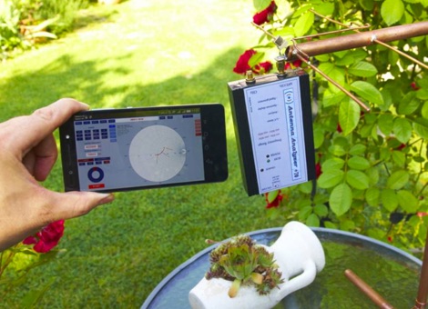 Antenna Analyzer plus 500 is a multifunctional measuring instrument, very useful for amateur radio activity. Its size allows you to easily take it for relocation as well. Frequency range: 100KHz - 500MHz. Access directly via WiFi. Includes a dual-channel signal generator
 -
 DF0WD/DL4YHF's Longwave Overview details amateur radio operations on the 135.7 to 137.8 kHz segment in Germany. The author outlines the "inofficial" European band plan, specifying segments for QRSS, TX tests, beacons, conventional CW, and data modes. Early LF activities at DF0WD began with a 20-watt CW transmitter, later upgraded to a homemade linear transverter capable of 100 watts, driven by an Icom IC706 on 10.137 MHz. The station's antenna system includes a 200-meter wire, approximately 10 meters above ground, supported by football field light-masts. Despite its length, the antenna's efficiency is noted as very low due to the immense wavelength of about 2.2 km. The author's experience highlights the significant challenge of achieving effective radiated power (EIRP) on LF, estimating DF0WD's EIRP at around 80 milliwatts based on field strength measurements from PA0SE. DF0WD/DL4YHF has successfully worked numerous countries on 136 kHz CW, including DL, F, G, GI, GM, GU, GW, HB9, HB0, LX, OE, OH, OK, OM, ON, OZ, PA, and SM. The author also mentions ongoing efforts to log contacts with CT, EI, LA/LG, and to complete a two-way QSO with Italy, demonstrating persistent activity on this challenging band.
 -
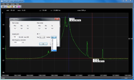 A project by LY3H of a complete Scalar USB network analyzer with freeware windows software, sweep range 100 kHz to 160 MHz, powered by USB.
 -
 The Delta Amateur Radio Club (DARC) serves as a community organization for amateur radio operators in the Memphis, Tennessee area, providing resources and activities centered around two-way radio communication. The club maintains the W4BS repeater system, which operates on 147.060 MHz with a +600 kHz offset and a 100 Hz PL tone, facilitating local VHF communications. DARC actively supports the Amateur Radio Emergency Service (ARES), preparing members for public service and disaster response through training and coordinated drills. The club also hosts regular meetings and events, fostering camaraderie and technical skill development among its members. Membership in the Delta Amateur Radio Club offers opportunities for participation in various amateur radio activities, including field day operations and local nets. The W4BS repeater provides reliable coverage across the Memphis metropolitan area, serving as a critical asset for both daily ragchewing and emergency traffic handling. DARC's affiliation with the Amateur Radio Relay League (ARRL) ensures access to national resources and advocacy, reinforcing the club's commitment to promoting amateur radio and public service within the community. The club's focus on emergency communications strengthens local preparedness.
 -
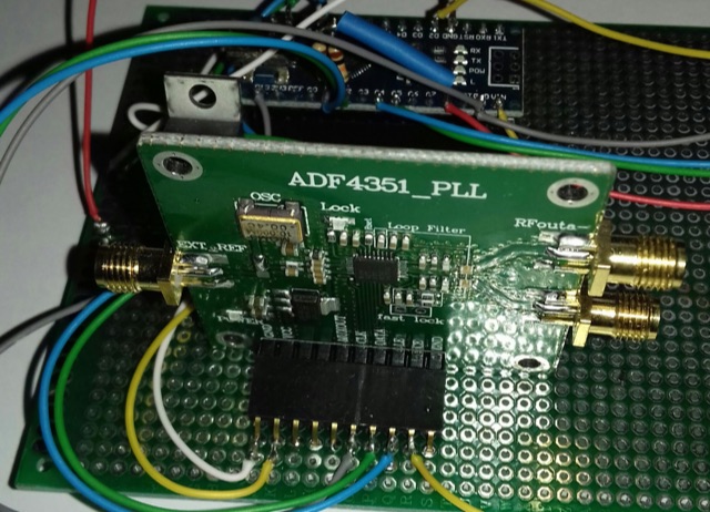 Just a simple signal generator based on ADF4351 module from fleebay allows you to generate one single frequency that can go up or down in 100Khz steps via two push buttons.
 -
 A medium power End Fed Half Wave Antenna coupler, specifically tuned to the QRP frequency of 7030 kHz. Constructed from coil stock and capacitors, it achieves an impedance ratio of 64:1. The coupler has proven effective for power ranges from 2 to 100 Watts on the 40m band.
 -
 This page provides a detailed guide on how to receive WWVB 60 KHz time signals using the Everset ES100 module with an Arduino Due microcontroller. It explains the background of time standards and the significance of WWV radio stations in maintaining these standards. The content is useful for ham radio operators interested in time synchronization, scientific research, navigation, and radio communications. The article is written by Keith Greiner, who shares his project inspired by his passion for the subject. For more projects by the author, visit the provided links.
 -
 This article details the design and construction of a compact 20-meter QRP SSB transceiver by Pete Juliano, N6QW, measuring just 2 x 4 x 2 inches—small enough for a shirt pocket. Inspired by a 1963 QST design and refined from a prior version, it employs bilateral circuits, a 4.9152 MHz homebrew crystal filter, switched-crystal VXO for 60 kHz coverage (14.160-14.220 MHz), and standard components like ADE-1L mixers and IRF510 PA for 1W output. Key innovations include a double-sided PCB skeletal frame for shielding and isolation, Vectorboard sub-assemblies, and ultra-miniature relays. The bilateral receiver/transmitter shares stages, omitting AGC for simplicity, while a W3NQN LPF and optional 10W external amp enable DX contacts. Tune-up focuses on crystal matching and bias for linearity. Videos on YouTube demonstrate performance, confirming excellent stability and audio. Total cost nears $100, prioritizing portability over features like CW.
 -
 A dual insert microphone design for the Icom IC-7300 transceiver utilizes a **Besson BZ2400 M4 Rocking Armature** insert for frequencies from 500 Hz to 3 kHz, exhibiting a rising response of approximately 11 dB. A generic Electret Condenser insert, powered by the transceiver's microphone line, covers the low-frequency range from 100 Hz to 500 Hz. A Low Pass Filter is incorporated after the Electret insert to prevent frequency overlap, and a pre-set potentiometer (VR1) adjusts the low-frequency response, balancing the output of both inserts. The design emphasizes a "Close Talking" arrangement and addresses audio "colorization" by housing the Besson insert in a thick rubber holder with a foam boot, separate from the circuitry, with the Electret insert also wrapped in a foam boot. Critical importance is placed on using the correct BZ2400 M4 insert with 12 holes in its face plate. The frequency response table for the BZ2400 M4 insert shows 0 dB at 500 Hz, rising to +11 dB at 3000 Hz, while the Electret insert with the Low Pass Filter provides 0 dB at 100 Hz, rolling off to -9 dB at 500 Hz and -50 dB at 3000 Hz. This combination ensures a broad, balanced audio spectrum for SSB operation. The project includes a circuit diagram, a comprehensive parts list detailing components like a 1 Henry iron-cored inductor (L1) and various capacitors, and a board layout within the metal tube. The completed unit provides a tailored audio profile for the IC-7300, enhancing transmit audio quality.
 -
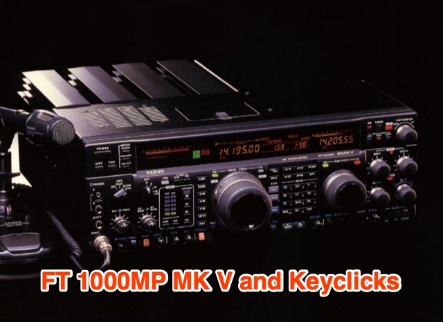 YaesuFT1000MK V stands out with improved close-spaced SSB transmit performance, reversing a trend seen in other modern radios. Featuring a class-A mode, it offers clean HV finals when kept out of ALC. However, two significant flaws persist: the noise blanker causes receiver IM distortion, and the transmitter lacks wave-shaping on CW, resulting in pronounced keyclicks. Preliminary tests reveal strong keyclicks +1kHz and -1kHz, prompting a combined modification to address both issues.
 -
 The **Yaesu FRG-100** shortwave receiver, introduced in 1992, operates across a frequency range of 50 kHz to 30 MHz, accommodating AM, LSB, USB, and CW modes, with an optional narrow-band FM capability. Its physical dimensions are 238 x 93 x 243 mm, with a weight of 3 kg, making it suitable for both portable and fixed station deployments. Power options include standard mains voltage or 12VDC, providing operational flexibility for diverse listening environments. The front panel integrates a manual tuning knob, an analogue signal strength meter, and an LCD display that provides critical information such as frequency, operating mode, memory channel, and time. Users can configure various operational parameters, including tuning steps and bandwidth filters, to optimize reception for specific signals. This review highlights the FRG-100's straightforward interface and its utility for shortwave listening enthusiasts. The design emphasizes user-friendly adjustments for settings, which contributes to its appeal among those interested in general coverage reception.
 -
 The author discusses ways to display VHF and higher bands using a K3/10 as transverter, NooElec Upconverter, SDR, and SDR-Console. He observed that the results were remarkable, with the tuned frequency visible at +/-100kHz. The K3 Interface Option (KXV3A) produces a buffered IF output at 8.213MHz, which is received using a NooElec NESDR SMArt SDR dongle and Ham It UP Upconverter. The SDR-Console program is utilized, with Omnirig synchronizing the SDR and K3. To configure the system, particular parameters are required, such as adjusting the IF frequency to 133.213MHz (125MHz + IF frequency) and inverting the spectrum. The Panadapter demonstrated ES activity at 10m, and modest software tweaks may be required for improved performance.
 -
 Demonstrates the construction of an active loop converter specifically designed for the Low Frequency (LF) bands, addressing common localized noise interference in LF reception. The design integrates a sharply tuned circuit and a tuned loop antenna, utilizing the loop as the sole tuned inductive element. By applying positive feedback, the converter significantly increases the loop's effective Q, achieving factors between 1000 and 2000, which sharpens tuning and reduces noise. The circuit employs an _NE602_ mixer stage, feeding its output to an HF receiver, with a crystal-locked local oscillator at 4 MHz. A 20-turn, 0.8-meter square loop antenna with 500 uH inductance is detailed, connected via 2 meters of figure 8 flex cable. The converter offers three selectable frequency bands: 195-490 kHz, 150-220 kHz (including the New Zealand amateur band), and 128-160 kHz (covering the European amateur band). Performance measurements indicate an effective 3dB bandwidth of approximately 100 to 200 hertz at 200 kHz. The article provides insights into component selection, including an _LF353_ op-amp and a trifilar wound transformer on a ferrite core. Sensitivity figures are presented, showing 7.5 uV of converted output per 1 uV/meter signal strength into a 50-ohm load, or 37.5 uV into an _FRG7_ receiver, highlighting its capability to extract weak signals from noise.