Search results
Query: all band transmit antenn
Links: 47 | Categories: 0
-
 Monitoring shortwave broadcast stations effectively requires accurate schedule information to identify transmissions. This online utility offers a straightforward, graphical interface designed to search for and display current shortwave radio broadcasting schedules. Users can precisely filter results by frequency, specific language, broadcaster, time of day, and even by shortwave band, which simplifies the process of pinpointing desired content. The database, last updated on March 26, 2023, details station callsigns (e.g., BBC), start and end times in UTC, days of the week, broadcast language, transmitter power in kilowatts, and azimuth. Crucially, it includes the precise geographical coordinates of transmitter sites, such as Woofferton in the UK or Al Seela in Oman. This data is invaluable for predicting signal paths and optimizing antenna direction for improved reception, a key consideration for serious SWLs. For instance, a search for BBC English broadcasts at 21:04 GMT quickly reveals multiple active frequencies like 17780 kHz from Woofferton, offering a clear overview of current transmissions. The tool processes queries rapidly, returning results within seconds, demonstrating its efficiency for broadcast listening enthusiasts seeking timely information.
 -
 This resource details the conversion of an 80m elevated vertical antenna to include 160m operation, focusing on a relay-switched design over a trap-based approach. It presents specific feedpoint impedance values, such as **32 ohms** for 80m and **14 ohms** for 160m, and discusses the challenges of SWR drift encountered with the prior trap system during RTTY contesting. The article thoroughly explains the design choices for elevated radials, referencing _N6LF QEX data_ to debunk common myths regarding radial length and height, demonstrating that non-resonant radials can offer superior current uniformity. The construction section provides practical insights into building the vertical, including guying strategies, material selection from scrap pipe, and weatherproofing the relay assembly. It highlights the use of a common mode choke for the relay switching line, measuring approximately 5K ohms on both 160m and 80m, and details the L/C matching network's role in achieving a 50-ohm match at the end of a 300-foot RG-11 run. The author describes a precise VNA-based radial trimming procedure, achieving resonant values within a 3 KHz range. The content emphasizes the practical application of theoretical antenna principles, particularly concerning the interaction between the vertical element, cap hats, and the matching network. It offers a candid assessment of component selection, such as using junkbox parts and acknowledging the need for future upgrades to static drain resistors. The article serves as a comprehensive case study for advanced antenna builders tackling multi-band vertical designs.
 -
 FDLog, a Python-based freeware application, addresses the challenge of synchronized logging for multi-station Field Day operations. It facilitates real-time data sharing across a wireless network, enabling operators to monitor band status and active transmitters at a glance. The software's input system is optimized for minimal keystrokes, streamlining the logging process during intense contest periods. Key features include database synchronization over a wireless network, ensuring all connected computers maintain identical log data. FDLog also incorporates a time synchronization function, designed to keep client programs within a second of a designated master machine, mitigating issues previously encountered with NTP. This internal clock sync can be optionally disabled if not required by the operating setup. Developed initially on Windows 2000, FDLog has demonstrated compatibility with _Linux_ and _macOS_ environments, though some font rendering issues may occur on the latter. The program assists in preparing the ARRL Field Day entry form, simplifying the submission of contest results. User feedback and ARRL rule changes drive ongoing development, with a discussion list available for community support and input.
 -
 One specific challenge in the KazShack, operating Single Operator Two Radios (SO2R), involved sharing a K9AY receive antenna between two transceivers without direct RF connection or manual feedline swapping. The solution, detailed in this project, adapts the **W3LPL RX bandpass filter** design to split 160m and 80m signals, feeding them to separate radio inputs while maintaining isolation. This approach also addresses the issue of strong broadcast band interference from a nearby 50KW WPTF transmitter on 680kc. The construction utilizes T-50-3 toroids and NP0 ceramic capacitors, built in a "dead bug" style on copper clad board. Each band's filter coils are identical and resonated to the desired frequency using an MFJ-259 antenna analyzer. A single DPDT relay, controlled by a remote toggle switch mounted on an aluminum panel, facilitates quick band switching between radios, simplifying low-band operations. While some signal loss is noted, the expected lower noise levels from the receive antenna are anticipated to compensate, potentially reducing the need for constant volume adjustments during toggling between transmit and receive antennas.
 -
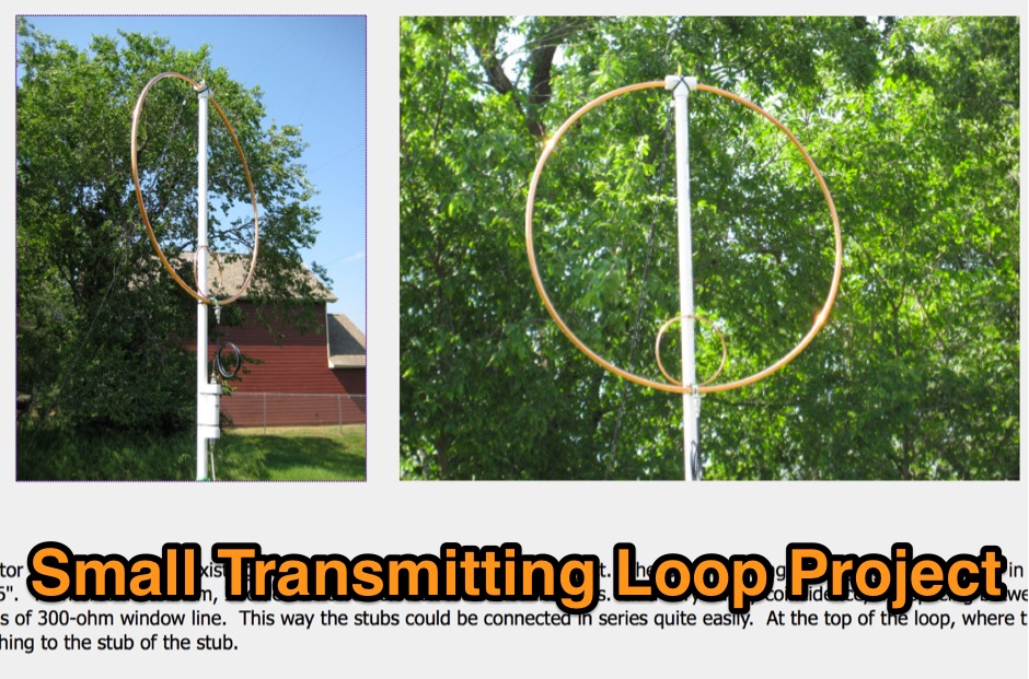
 For radio amateurs seeking compact and efficient antenna solutions, particularly for restricted spaces or noise reduction, HF loop antennas present a viable option. This resource compiles several articles from the ARRL, detailing the theory, design considerations, and practical construction of various loop configurations. Topics include small transmitting loops, receiving loops, and multi-band designs, often emphasizing their performance characteristics such as directivity, bandwidth, and impedance matching. The collected articles provide insights into the comparative performance of different loop geometries, such as circular versus square loops, and discuss the impact of conductor size and tuning methods on efficiency. Practical applications are explored, including their use in portable operations, stealth installations, and urban environments where noise mitigation is critical. The content often includes construction diagrams, parts lists, and performance data derived from modeling or field tests, enabling hams to replicate or adapt the designs for their specific operating conditions.
 -
 Optimizing a G5RV or ZS6BKW multiband wire antenna for HF operation often involves addressing common SWR issues and understanding feedline characteristics. This resource chronicles the construction and performance evaluation of a G5RV, initially built for 80m, 40m, 15m, and 10m bands, by a newly licensed Foundation operator. The author details the selection of materials, including 3.5 mm stainless steel wire for the doublet arms and enameled copper wire for the open-wire feeder, and the initial decision to omit a balun based on common online information. The narrative highlights the initial disappointing performance, characterized by high receive noise and poor signal reports on 80 meters, despite the transceiver's internal ATU achieving a 1:1 match. This led to experimentation with a coax current balun and further research into G5RV myths, such as SWR claims and the necessity of a balun. The author then describes modifying the antenna to the ZS6BKW configuration, which involves specific changes to the doublet and feedline lengths, and integrating a 1:1 current balun wound on a ferrite toroid. The modifications resulted in improved reception and transmit performance across the bands.
 -
 The NCDXF/IARU International Beacon Project operates a worldwide network of 18 high-frequency radio beacons, continuously transmitting on 14.100, 18.110, 21.150, 24.930, and 28.200 MHz. These beacons, initially launched in 1979 with a single station and expanded to the current 18-beacon system in 1995, provide reliable signals for both amateur and commercial users to assess current **ionospheric propagation** conditions. The system's design, construction, and operation are managed by volunteers, covering hardware and shipping costs. The resource details the evolution of the beacon network, including the transition from Kenwood TS-50s transmitters to Icom IC-7200 radios with a new controller design implemented in 2015. It explains how listening for these 100-watt signals, transmitted to vertical antennas, allows operators to determine band openings and optimal propagation paths globally. The content also references three QST articles providing historical context and technical specifics of the beacon project. Practical information includes methods for identifying transmitting beacons via a schedule or specialized software like FAROS and Skimmer, which integrates with the **Reverse Beacon Network** for automated monitoring.
 -
 Presents a QRP AM/CW transmitter project specifically designed for the 10-meter band, utilizing a crystal oscillator and a collector-modulated AM oscillator. The design employs a 2N2219(A) transistor in a Colpitts configuration, generating 100 to 350 mW of RF output power depending on the 9-18 Volt supply voltage and modulation depth. Frequency stability is maintained by a 28 MHz crystal, with fine-tuning possible via a Ct1 trimmer capacitor for approximately 1 kHz adjustment. The resource details the RF oscillator stage, implemented with a 2N2219 NPN transistor, emphasizing frequency stability and low power dissipation. It also covers the amplitude modulation stage, managed by a 2N2905 PNP transistor, which impresses audio information onto the carrier. Selective components (C3, C4, C7, C5) enhance voice frequencies within a +/- 5 kHz bandwidth, and modulation depth is controlled by R2 and R3. The project includes a 3-element L-type narrow bandpass filter (Ct3, L3, C10) to suppress harmonics and ensure a clean output signal. The project provides a complete schematic diagram, a comprehensive parts list including specific capacitor, resistor, and inductor values, and construction notes for the coils (L1, L2, L3). It also offers practical advice on enclosure requirements, suggesting an all-metal case or a PVC box with graphite paint for RF shielding. Operational parameters such as current draw (27mA@9V to 45mA@16V) and input impedance (50 Ohms) are specified, alongside guidance on antenna matching and the importance of a valid amateur radio license for 10-meter band operation.
 -
 Article about small magnetic loop antennas with notes on realization of magnetic loops for several HF bands and the six meter band
 -
 The 10-minute, 25-second video demonstrates making a QSO via the VO-52 amateur radio satellite, focusing on real-time Doppler shift correction. It features Simon, 2E0HTS, operating a Yaesu FT-847 transceiver and a homebrew dual-band Yagi antenna, specifically a 10-element 435 MHz Yagi for uplink and an IO Loop for 145 MHz downlink. The video visually details the operator's technique for continuously adjusting the uplink frequency to compensate for the satellite's changing velocity relative to the ground station, a critical aspect of successful satellite communication. The demonstration highlights the practical application of Doppler compensation, showing the operator tuning the transmit frequency to maintain a stable received signal from the satellite. This approach contrasts with systems employing automatic Doppler correction or full-duplex operation, providing insight into manual frequency management for satellite passes. The video serves as a direct, observational guide for hams interested in LEO satellite operations, particularly those using non-tracking, manually tuned setups.
 -
 Demonstrates the operational status and reception reports for the SK6RUD/SA6RR QRPP beacons, which transmit on 478.9 kHz, 1995 kHz, 10.131 MHz, and 40.673 MHz. These beacons utilize extremely low power, with the 630-meter beacon operating at approximately 0.1 watt ERP into an L-antenna, showcasing the potential for long-distance contacts under favorable propagation conditions. The site details the specific frequencies and antenna types employed, such as a vertical at 500 kHz and a 1/4 vertical for higher bands. The resource compiles over 10,530 reception reports from amateur radio operators worldwide, logging details such as date, time, band, RST signal report, locator, distance, and receiver setup. Notable long-distance reports include a 500 kHz reception by AA1A-Dave from 5832 km in 2008 and a 10.133 MHz reception by ZL2FT-Jason from 17680 km in 2010, illustrating the global reach of these low-power transmissions. Each log entry provides specific equipment used by the reporting station, including transceivers like the Yaesu FT817, ICOM IC-7300, and various antenna configurations such as coaxial mag loops, inverted Ls, and end-fed wires. The primary objective of the SK6RUD beacons is to challenge conventional notions of power requirements for effective two-way communication, proving that contacts over significant distances are achievable with minimal output. The site also includes a submission form for new reception reports, fostering community engagement and continuous data collection on propagation phenomena across different bands. The detailed logs offer practical insights into real-world propagation characteristics and the efficacy of QRPP operations.
 -
 Antenna tuners are crucial for matching the impedance of antennas to the 50 ohm output impedance of transmitters. The _LDG Z-11 Pro_ is an automatic antenna tuner designed to handle up to 125 watts, making it suitable for a wide range of amateur radio applications. Its compact form factor allows it to pair well with transceivers like the _FT-857D_, providing a portable solution for operators who frequently change locations or setups. The tuner covers the 80 through 6 meter bands, offering a broad impedance match capability. Although it struggles with some loads, it performs well with typical ham antennas, even managing to load an 80 meter dipole on 6 meters. One of the standout features of the _Z-11 Pro_ is its 8000 memory slots, which enable it to remember successful matches and quickly retune when revisiting frequencies. This memory function significantly reduces tuning time, often to less than half a second. The unit is well-constructed, with improved pushbuttons and a sturdy metal case that offers good shielding. However, users should be aware of potential RFI issues and the lack of a power switch, which requires disconnecting the power cord to turn off the unit completely. Overall, the _LDG Z-11 Pro_ is a user-friendly and cost-effective tuner, offering advanced features that enhance its utility in various amateur radio setups.
 -
 Hi-Z Antennas offers specialized high-impedance receiving systems, primarily focusing on phased vertical arrays for HF reception. Their product line includes preamplifiers designed for shortened vertical antennas, featuring optimized 15dB gain and array-matched characteristics. These components are engineered to enhance weak signal reception and improve signal-to-noise ratio across the HF spectrum. The company provides controllers for managing multiple vertical elements in a phased array configuration, enabling directional reception patterns. These systems are particularly effective for mitigating local noise and interference, a common challenge in urban and suburban operating environments. Specific offerings include solutions for 160-meter and 80-meter bands, addressing the unique requirements of low-band DXing. Technical details often reference components like the 2N3866 transistor in preamp designs and discuss concepts such as out-of-band attenuation. The focus remains on optimizing receiving antenna performance through impedance matching and active amplification, rather than transmit capabilities.
 -
 A 200 kHz bandwidth digital transmission system for image transfer in the Amateur Service is under development, specifically targeting VHF allocations. John B. Stephensen, KD6OZH, leads this project under an FCC Special Temporary Authority (STA) valid until September 10, 2006, authorizing emissions up to 200 kHz bandwidth in the 50.3-50.8 MHz segment. Current regulations typically limit bandwidths to 20 kHz on VHF amateur bands, making this STA crucial for testing wideband digital modes. The modem, a modified **OFDM** (Orthogonal Frequency Division Multiplexed) unit, was initially tested on the 70-cm band. It splits a high-rate data stream into multiple low-rate subcarriers to mitigate multipath echoes. The system uses a DCP-1 card with a Xilinx XC3S400 FPGA and Oki Semiconductor ML67Q5003 microcontroller. The transmitter, located at 36d 46m 30s N, 119d 46m 22s W, generates 150 WPEP into an 8 dBi gain vertical antenna, while the mobile receiver uses a Ham-stick. Three data formats for 50, 100, and 200 kHz channels are being tested, with encoded data rates of 96, 192, and 384 kbps. Verilog code for the VHF OFDM modem is 95% simulated, with modifications from the UHF version including increased filter coefficient precision and a change from Ungerboeck **TCM** to BICM for improved performance over fading paths. Final tests will involve one-way over-the-air measurements of bit error rates and coverage area.
 -
 The article, "Using 75 Ohm CATV Coaxial Cable," details methods for employing readily available 75-ohm CATV hardline in standard 50-ohm amateur radio setups. It addresses the inherent impedance mismatch and practical considerations, such as connector compatibility, for hams seeking cost-effective, low-loss feedline solutions. The resource specifically contrasts common 50-ohm cables like RG-8, RG213, and _LMR-400_ with 75-ohm hardline, highlighting the latter's lower loss characteristics, particularly at VHF and UHF frequencies. It explores two primary approaches to manage the impedance difference: direct connection with an acceptable SWR compromise and precise impedance transformation. The direct connection method acknowledges that a perfect 1:1 SWR is not always critical, especially when using low-loss coax. For impedance transformation, the article explains the use of half-wavelength sections of coax to reflect the antenna's 50-ohm impedance back to the transmitter, noting its single-frequency effectiveness. It also briefly mentions transformer designs using toroid cores and a technique involving two 1/12 wavelength sections of feedline for broader bandwidth. The content further clarifies the concept of _velocity factor_ for calculating electrical versus physical cable lengths, providing a generic formula for precise length determination. It notes that while half-wave matching is practical for 10 meters and above, it can result in excessively long runs for lower bands like 160 meters, potentially adding **250 feet** of cable. The article also mentions achieving a usable bandwidth of 28.000 MHz up to at least **28.8 MHz** on 10 meters with specific transformation techniques.
 -
 The Kenwood TS-870S HF transceiver features two state-of-the-art 24-bit 20 MIPS DSP chips, providing over 100dB out-of-passband attenuation and CW bandwidth adjustable to 50 Hz. It operates across 160-10 meters with 100 watts output, incorporating digital filtering, a beat canceller, and 100 memory channels. The radio also includes a transmit equalizer, RX antenna input, and a K1 Logic Keyer, enhancing signal processing and operational flexibility for amateur radio operators. Advanced capabilities include IF stage DSP, dual noise reduction, and an auto notch filter, all contributing to superior signal reception and clarity. The TS-870S offers a variable AGC, voice equalizer, and an RS-232C port for computer control, with Windows™ software supplied. Its built-in automatic antenna tuner functions on all bands for both transmit and receive modes, streamlining station setup and operation. Available accessories such as the DRU-3A digital recording unit, SO-2 high stability crystal oscillator, and VS-2 voice synthesizer option further extend the transceiver's utility. The unit requires 13.8 VDC at 20.5 Amps and is supplied with an MC-43S hand microphone, making it a comprehensive station component.
 -
 Amateur Television (ATV) operations involve transmitting and receiving live or recorded video and audio signals over amateur radio frequencies. Unlike narrow-band modes, ATV utilizes a wider bandwidth to convey video information, often requiring specialized transceivers, antennas, and signal processing equipment. This mode allows hams to share visual content, demonstrate projects, or conduct video conferences, typically on VHF, UHF, and microwave bands due to the bandwidth requirements. The SwissATV resource focuses on the technical aspects and community engagement surrounding ATV within Switzerland. It covers topics relevant to setting up ATV stations, understanding signal propagation at higher frequencies, and participating in local ATV activities. The site serves as a central point for Swiss ATV operators to exchange knowledge and coordinate transmissions, fostering the growth of this specialized amateur radio mode.
 -
 Sixty-meter repeaters typically use a 1 MHz frequency separation between input and output, while 2-meter repeaters commonly employ a **600 kHz** split and 70-centimeter repeaters use a **5 MHz** offset. This article details the fundamental technical principles of amateur voice repeaters, explaining how they extend VHF/UHF communication range by receiving on one frequency and simultaneously retransmitting on another. It covers essential components such as receivers, transmitters, filters, and antennas, often situated on elevated locations for optimal coverage. The resource delves into the critical challenge of _desensing_—where the repeater's strong transmit signal overpowers its own receiver—and the engineering solutions employed, including antenna separation and the use of high-Q cavity filters. It also explores various control and timing systems, from basic squelch activation to more sophisticated microcontroller-based boards that manage functions like voice identification, time-out timers, and fault protection. Different access methods are discussed, including open access, toneburst, CTCSS subtone, and DTMF, each offering distinct advantages for managing repeater usage and mitigating interference. Furthermore, the article examines repeater linking, both conventional RF methods and modern internet-based solutions, highlighting how linking expands coverage and promotes activity across multiple repeaters or bands. It introduces less common repeater types such as 'parrot' repeaters, which use a single frequency and digital voice recording, and linear translators, capable of relaying multiple signals and modes simultaneously across different bands, often found in amateur satellites.
 -
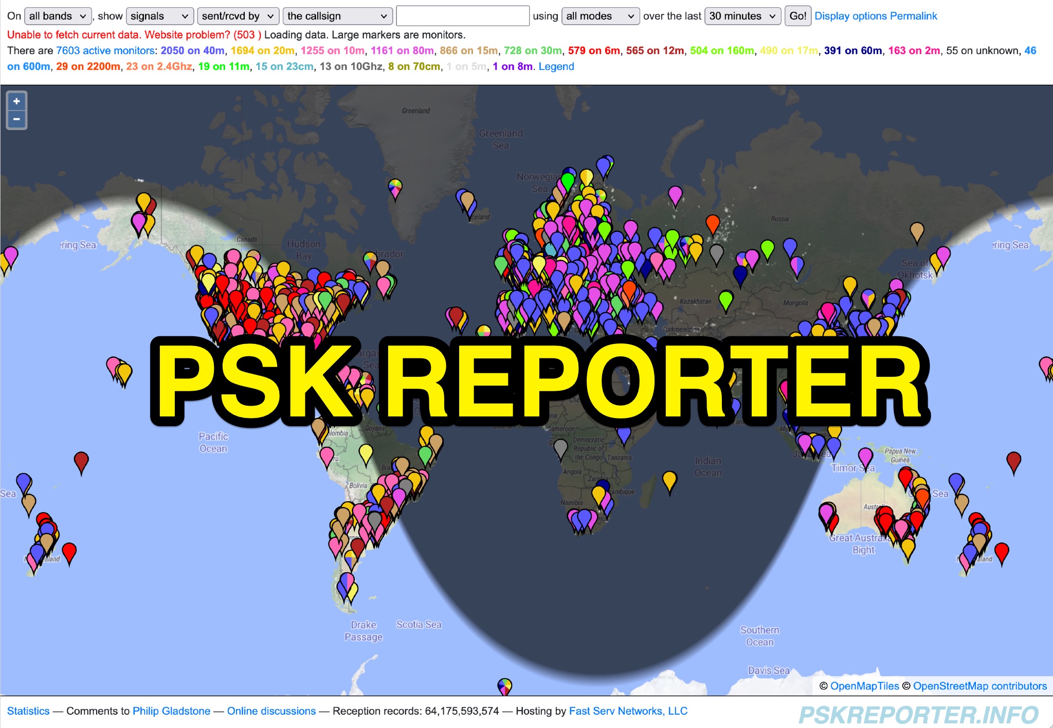 PSK Reporter provides a real-time visualization of amateur radio digital mode reception reports, aggregating data from a global network of monitoring stations. This platform is particularly useful for operators utilizing modes such as FT8, FT4, and PSK, allowing them to observe signal propagation paths and assess their station's reach. The interactive maps display reception reports, enabling hams to analyze band conditions and optimize antenna performance for various frequencies and times of day, aiding in understanding ionospheric conditions. Operators can filter reports by callsign, band, mode, and time, gaining insights into specific propagation events or evaluating the effectiveness of their transmit setup. The data collected helps in predicting optimal operating windows for DX contacts across various digital modes. Philip Gladstone is the contact person for comments and discussions regarding the system.
 -
 Developing operational amateur radio equipment for the 134 GHz band presents significant technical challenges, particularly in frequency generation and stability. This resource details the construction of a 134 GHz system, outlining its architecture with separate transmit (Tx) and receive (Rx) modules, each employing a local oscillator (LO) and RF head units. The system utilizes a dual Flann 50 GHz lens-type horn antenna configuration for optimal signal coupling. The transmit path incorporates an LMX2541 synthesizer chip operating at approximately 2.8 GHz, referenced by a 10 MHz double-oven Morion OCXO for exceptional stability. This signal is multiplied through a series of stages (X4, then X2) to generate a 22.4 GHz signal, which subsequently drives a dual series diode multiplier to produce the final X6 signal for 134 GHz operation. The receive side features an anti-parallel diode mixer coupled to a 144 MHz transceiver via a preamplifier, ensuring effective downconversion. Operational mode is CW, achieved by keying a multiplier stage. The project includes images of the Tx and Rx head units and describes a successful 3.5 km test with G8ACE, demonstrating stable signal tones due to PLLs locked to OCXOs at both ends, confirming the system's robust performance.
 -
 Designing and constructing a two-element receiving loop antenna array for HF operation involves specific considerations for achieving high directivity and noise reduction. This resource details a homebrew system comprising two 30-inch diamond-shaped loops, spaced 20 feet apart, which are fed through mast-mounted preamplifiers and passive signal combiners. The operational principle relies on adjusting phase delays between elements via precise _Belden 8241_ coaxial cable lengths, optimized for specific bands from 160m to 20m. Performance data, derived from _EZ-NEC_ modeling, illustrates consistent 90° azimuth-plane beamwidth and low take-off angles across the target bands, with _Receiving Directivity Factor_ (RDF) values comparable to a 300-foot Beverage antenna. The article presents detailed elevation and azimuth plots for 20m, 30m, 40m, 80m, and 160m, demonstrating the array's ability to provide strong response at low DX angles while also supporting _NVIS_ signals. Key components like the _DX Engineering RPA-1_ preamplifier and _DXE RSC-2_ signal combiner are discussed, alongside the importance of impedance matching to preserve antenna patterns. The construction emphasizes self-contained elements that do not require ground radials, offering a compact solution suitable for suburban environments and stealth installations, with a focus on optimizing receive performance independently from transmit antennas.
 -
 The ZS1J/B beacon operates on 28.2025 MHz with 5 Watts output to a half-wave, end-fed vertical antenna, initially installed in 1977 as ZS5VHF near Durban. The 10-meter transmitter is a modified 23-channel CB radio, and the identification keyer uses a diode matrix unit with TTL ICs from the same era. After relocation to Plettenberg Bay in 1993, the beacon has been in continuous service, with additional QRP transmitters later installed for other bands. In 1994, a single-transistor, 80-meter, 0.5-watt QRP transmitter with a half-wave dipole was added on 3586 kHz, followed by a 160-meter, 0.5-watt unit on 1817 kHz. A 30-meter, 0.5-watt transmitter was installed in 1996, operating on 10.124 MHz. In 2002, a 40-meter QRRP beacon on 7029 kHz, with an output of 100 microwatts, achieved DX reports up to 1100 km from ZS6UT in Pretoria. Best DX reports for the 80m and 160m beacons came from 9J2BO.
 -
 Low-frequency (LF) radio time signals, operating primarily in the 40–80 kHz range, are broadcast by national physics laboratories for precise clock synchronization. Transmitters like **JJY** (40 kHz, 50 kW; 60 kHz, 50 kW), RTZ (50 kHz, 10 kW ERP), MSF (60 kHz, 15 kW ERP), WWVB (60 kHz, 50 kW ERP), RBU (66.66 kHz, 10 kW), and DCF77 (77.5 kHz, 50 kW) cover vast geographic areas, often several hundred to thousands of kilometers. LF signals offer distinct propagation advantages over higher-band transmissions such as GPS. Their long wavelengths (3–6 km) enable effective diffraction around obstacles like mountains and buildings. The ionosphere and ground act as a waveguide, eliminating the need for line-of-sight and allowing a single powerful station to cover extensive regions. Ground wave propagation minimizes ionospheric variability effects on transmission delay, and signals penetrate most building walls effectively. Robust and low-cost receivers, often priced at 20–30 USD/EUR, are widely used in radio clocks. These receivers typically comprise a tuned ferrite core antenna, a receiver IC (e.g., Atmel T4227, U4223B, MAS1016) for amplification and AM detection, and a microcontroller for decoding the time signal and phase-locking a local clock. Specific components for DCF77, MSF, and WWVB are readily available from vendors like HKW Elektronik and Ultralink.
 -
 Thsi article describes a microcontroller driven semi-automatic antenna tuner capable of handling power levels up to 150 watts. The device is a low pass filter tuner manually tuned by setting the optimized L/C combination by hand and then storing the values into the EEPROM of the mictrocontroller to recall them later (seperately for each band from 80 to 10 meters including WARC bands)
 -
 High Speed Multimedia (HSMM) radio, as introduced by John Champa, K8OCL, represents a significant advancement in amateur radio's digital capabilities, moving beyond traditional keyboard modes like packet radio. This initiative, driven by ARRL's Technology Task Force, focuses on developing high-speed digital radio networks capable of up to 20 megabits per second. HSMM primarily facilitates digital voice (DV) and digital video (ADV), enabling real-time video transmission from emergency scenes to an EOC without expensive ATV gear, often requiring only a laptop, a PCMCIA card, a digital camera, and a small antenna. The working group's initial efforts concentrate on cultivating microwave skills within the amateur community to build and support portable and fixed high-speed radio-based local networking, or **RLANs**. These networks prove invaluable for RACES and ARES organizations, as well as homeland security and other emergency communications. Field Day exercises and simulated emergency tests (SETs) are encouraged to hone skills in rapid site surveys and deploying broadband HSMM microwave radio networks, with examples like linking Field Day logging stations or antenna test results at the Midwest VHF-UHF Society Picnic 2003. Getting started with HSMM often involves adapting off-the-shelf **IEEE 802.11** (WiFi) equipment to comply with amateur radio regulations, typically operating in the 2.4 GHz ISM bands. While consumer WiFi gear has range limitations under Part 15 rules, proper setup under amateur regulations can extend coverage significantly, with test networks like the Hinternet achieving 5-15 mile ranges at 54 M bit/s using small mast-mounted dish antennas. Careful selection of equipment with external antenna ports, high transmit power, and low receive sensitivity is crucial, along with using low-loss coaxial cable like LMR-400 for optimal performance at these frequencies.
 -
 Operating in a Single Operator Two Radios (SO2R) setup, especially with beverage antennas, often exposes the receiving radio's front-end to significant RF energy from the transmitting radio. This resource details a practical, homebrew receiver protection circuit designed to mitigate this risk. The core of the design involves a non-inductive 2W 22 Ohm carbon composition resistor in series with the RX antenna line, followed by two stacks of four fast-switching diodes (e.g., _1N914_) configured in opposite polarizations. This arrangement effectively clamps the incoming voltage to approximately 2.8 V peak-to-peak, safeguarding sensitive receiver input components. The series resistor plays a crucial role by absorbing excess power, preventing the diodes from exceeding their current ratings and potentially failing open, which would leave the receiver unprotected. The author, _N4KG_, measured up to 50 watts of coupled power between 80M slopers on the same tower, highlighting the necessity of such protection. The design is presented as a cost-effective solution to prevent damage to receiver input transformers, with the author noting successful protection of a receiver even after a resistor showed signs of overheating. This simple circuit can be integrated via a transverter plug, offering a robust defense against high RF input.
 -
 DF0WD/DL4YHF's Longwave Overview details amateur radio operations on the 135.7 to 137.8 kHz segment in Germany. The author outlines the "inofficial" European band plan, specifying segments for QRSS, TX tests, beacons, conventional CW, and data modes. Early LF activities at DF0WD began with a 20-watt CW transmitter, later upgraded to a homemade linear transverter capable of 100 watts, driven by an Icom IC706 on 10.137 MHz. The station's antenna system includes a 200-meter wire, approximately 10 meters above ground, supported by football field light-masts. Despite its length, the antenna's efficiency is noted as very low due to the immense wavelength of about 2.2 km. The author's experience highlights the significant challenge of achieving effective radiated power (EIRP) on LF, estimating DF0WD's EIRP at around 80 milliwatts based on field strength measurements from PA0SE. DF0WD/DL4YHF has successfully worked numerous countries on 136 kHz CW, including DL, F, G, GI, GM, GU, GW, HB9, HB0, LX, OE, OH, OK, OM, ON, OZ, PA, and SM. The author also mentions ongoing efforts to log contacts with CT, EI, LA/LG, and to complete a two-way QSO with Italy, demonstrating persistent activity on this challenging band.
 -
 A magnetic loop antenna designed for 14 MHz. This kind of antennas is also known as STL, small transmitting loop and can be an excellent solution when you are not allowed to put antennas on your roof
 -
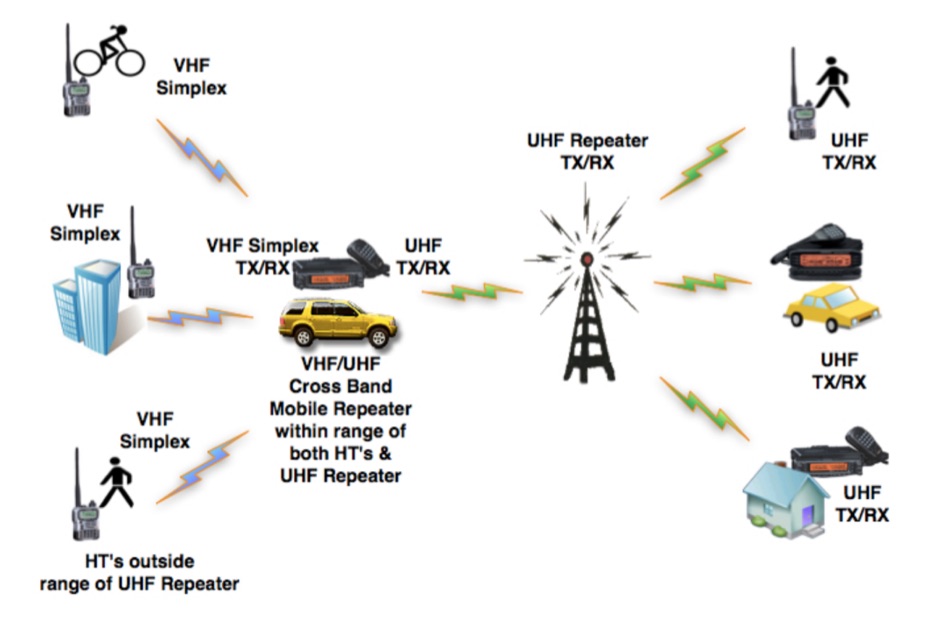 Crossband Repeating is a process where a Ham transmits one signal on one band (typically UHF), and it is received by another radio with a better antenna/power installation, and re-transmitted (typically on VHF) to another radio system, or a repeater. Everyday examples of cross-band repeaters are repeater receive sites that hear the input signals on 2m and retransmit those signals on a frequency higher than 220 MHz.
 -
 Explains the fundamental purpose of a repeater, detailing how these automated relay stations overcome distance and terrain limitations for VHF/UHF communications. It traces the historical development from early Bell Telephone Labs "relay" stations in 1922 to Art Gentry, W6MEP's, pioneering K6MYK amateur radio repeater in the mid-1950s, which remains active today. The resource clarifies the distinction between simplex and duplex operation, including the unique function of a "parrot repeater" for single-frequency recording and playback. Delving into the internal workings, the guide breaks down a repeater into its core components: the antenna system, feedline (often _Heliax_ or hardline for minimal loss), duplexer, receiver, transmitter, and controller. It emphasizes the critical role of the duplexer in preventing receiver desensitization by isolating transmit and receive signals, even with distinct frequencies. The discussion highlights the importance of high-performance, durable antennas and low-loss feedlines, citing examples of equipment installed in the 1960s and 1970s that are still in perfect working order. Operating a repeater is also covered, with an explanation of frequency offset (e.g., the 600 kHz standard for 2 meters) and the function of _CTCSS_ (PL tone) for access. It outlines standard input/output offsets for various bands, from 6 meters to 23 centimeters, while noting regional variations. The guide also touches on features like autopatch and Digital Voice Recorders (DVRs), providing a solid foundation for understanding repeater technology and usage.
 -
 The _G3TSO_ Mobile Antenna Page details construction and tuning methods for mobile antennas operating across **10 to 160 metres**. The content describes a Hustler-based design, optimized for RF performance and vehicle speeds, featuring centre loading. For optimal operation on various bands, the loading coil placement requires clearance from the vehicle body. Antenna resonance is critical for efficient mobile operation. A mobile antenna's base impedance may be as low as 27 ohms, requiring specific matching to achieve maximum radiation, as a minimum SWR at the transmitter does not always indicate resonance or maximum output. Tuning involves physical adjustment of antenna length to achieve resonance at the operating frequency. The _G3TSO_ page outlines a tuning procedure utilizing a low-power signal source and a field strength meter to identify maximum radiation before impedance matching. Loading coil placement, either at the base, center, or top of the antenna, influences radiation efficiency and mechanical stability for mobile installations. Centre-loaded whips, such as the Hustler design, offer a compromise between efficiency and stability, often for single-band operation. Helically wound antennas, including those for **28 MHz**, may present base impedances around 17 ohms, resulting in a 3:1 SWR at resonance. Low resistance grounding at the antenna base is also specified for optimizing performance and minimizing RFI during mobile operation. DXZone Focus: Mobile | Any | Antenna Tuning | HF
 -
 Vertical antenna tests at the Sonten-Rancabali tea resort in Ciwidey, West Java. The assembly, led by Mr. Dian Kurniawan and the team, took just 20 minutes. Mrs. Mita performed the transmit check-in test, which was received across various regions in Indonesia, including Sulawesi, East Java, and Bangka Belitung. The team will release a video of the test soon and has thanked colleagues YB3HRY and YB0BAW for their reports.
 -
 WB8LZR details the construction and initial field results of a multi-band vertical wire antenna, designed to complement his existing horizontal loop for improved DX on 80 meters. The antenna utilizes a 67-foot vertical wire, configured as a quarter-wave radiator on 80m, and employs a 1:1 current balun for RF isolation on 80m, 30m, and 17m. For bands like 40m, 20m, and 10m, where the wire acts as a half-wave or full-wave radiator, an additional impedance transforming _unun_ is integrated to manage the significantly higher feedpoint impedance and voltage. The author notes the vertical's performance as a receiving antenna, observing reduced noise compared to his main horizontal loop, particularly on 80m, and even hearing some long-path signals the loop missed. Initial QRP contacts, including a **1-watt** QSO with a _VP2 station_ on 30m, demonstrate its transmit capability. While the radial system is currently rudimentary, the project outlines practical considerations for multi-band vertical deployment and impedance matching.
 -
 Presents two distinct hardware modifications for the Icom IC-7300 transceiver, detailing the necessary steps for each. The first modification, a _MARS_ transmit expansion, involves the physical removal of specific surface-mount diodes (D422) from the main board, enabling transmit capabilities across a broader frequency range, including out-of-band frequencies. It specifies the diode location on US versions of the IC-7300 and suggests using small diagonal cutters if a soldering iron is not preferred or available. The second modification focuses on the internal antenna tuner, aiming to provide wider impedance matching capabilities. This involves adding a **100k ohm** resistor to a designated point within the tuner circuit. The resource also briefly mentions a microphone modification for the _HM219_ and a general power increase, though without specific instructions for the latter two. It emphasizes safety precautions, such as disconnecting power and inspecting the work area.
 -
 The document details the construction and performance of a rotatable flag antenna designed for a small lot. The 7x14 feet flag, built with fiberglass poles and an aluminum hub, shows improved reception compared to the author's previous transmit antenna. Key components include a conventional transformer for impedance matching and a variable resistance termination system to optimize performance. Despite challenges like nearby objects affecting signal patterns, the antenna consistently provides better signal-to-noise ratios, making it a valuable addition for low-band listening in suburban areas.
 -
 The author describes his experience building and using a Beverage antenna for the 40-meter band. Despite encountering some challenges, the antenna offered some improvements in receiving stations compared to a 3-element inverted Vee antenna. The Beverage antenna showed a significant daytime signal-to-noise ratio improvement and received signals better than the Vee antenna. However, the front-to-back ratio was not ideal, and the transmit power seemed to affect the Beverage antenna. Overall, the author concludes that the Beverage antenna might be more suitable for locations with higher noise levels. The total cost of the antenna was around 30 Euros.
 -
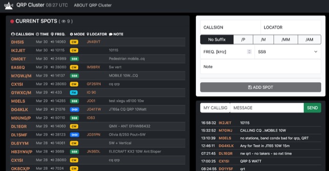 The QRP Cluster provides a dedicated platform for _QRP_ (low power) amateur radio operators to self-spot their on-air activity. This web-based service allows users to post real-time information about their current operating frequency, modulation mode, equipment used, and transmit power. It facilitates QRP-to-QRP contacts and helps other low-power stations locate active QRP signals across various bands. Unlike general DX clusters, the QRP Cluster focuses exclusively on low-power operations, fostering a community for QRP enthusiasts. It enables operators to share details such as **5 watts** or less output, often specifying antenna types or unique portable setups. The platform supports the discovery of QRP stations for casual QSOs, contests, and award hunting, enhancing visibility for stations that might otherwise be overlooked on higher-power clusters.
 -
 The most basic form of repeater receives communication on one frequency and re-transmits it on a different frequency, a process known as duplex communication. This capability significantly extends the range of handheld and mobile radios, as repeaters are typically situated at elevated locations with high-gain antennas and greater transmit power. Repeaters commonly operate with FM modulation on the VHF (30 MHz – 300 MHz) and UHF (300 MHz – 3 GHz) amateur bands, which are ideal for portable and mobile devices. Access to repeaters is often controlled by a CTCSS or PL tone, an inaudible signal that prevents the repeater from retransmitting background noise. This mechanism ensures efficient use of the frequency and prevents illegal continuous transmission. Canadian regulations, for instance, require an Advanced amateur radio license and an available frequency within the band to set up a repeater, each assigned a unique call sign and transmit frequency. Configuring a radio for repeater use involves knowing the repeater's transmit frequency, its receive frequency offset (e.g., -600 KHz for VHF or +5 MHz for UHF), and the necessary CTCSS tone. The article references resources like Repeater Book for locating repeaters and provides practical examples for initiating and concluding a basic repeater session, emphasizing clear identification and concise communication.
 -
 A detailed guide presents a simple 2-element quad antenna for 2m, offering ease of construction, portability, and efficient performance across the 144-148 MHz band. The design allows quick disassembly for storage and features adjustable polarization, making it ideal for various applications, including transmitter hunting and SSB operations.
 -
 Chavdar Levkov, LZ1AQ, presents an experimental comparison of small wideband magnetic loops, building on his previous work on wideband active small magnetic loop antennas. His research focuses on increasing loop sensitivity by maximizing the short-circuit current, which is directly tied to the "loop factor" M = A/L, where A is the equivalent loop area and L is its inductance. Levkov's methodology involves reducing inductance and increasing area through parallel or coplanar crossed (CC) configurations, comparing these designs against a reference single quad loop of 1 m2 area. Experimental verification included testing three distinct loop types: a simple quad loop, two coplanar crossed (CC) loops, and eight parallel loops, all designed to have a total geometric area of 1 m2. Measurements were conducted at 1.8, 3.5, 7, and 10 MHz using a small transmitter 270 meters away, with a Perseus direct sampling receiver for precise signal level assessment. The results consistently showed that CC loops, particularly Loop 5 (two CC circular loops with 1.44 m2 total area), yielded significantly higher currents, up to 9.1 dB over the reference loop at 3.5 MHz, validating M as a reliable predictor of loop sensitivity. Numerical simulations using MMANA further corroborated the experimental findings, demonstrating an almost perfect correlation between the calculated M factor and the induced loop current for 15 different loop models. Levkov concludes that CC loops offer superior sensitivity for a given loop area, while parallel loops are advantageous for minimizing physical volume. Practical recommendations suggest using loops with an M factor greater than 0.5 uA/pT for quiet rural environments, and he provides a spreadsheet tool, WLoop_calc.xls, to aid in optimizing loop configurations for specific operational needs.
 -
 Effective suppression of harmonics and parasitic radiation from HF transmitters is crucial, especially with the increasing sensitivity of VHF/UHF radio channels to interference. This project details a hybrid low-pass filter (LPF) designed to operate across the HF bands up to 51 MHz, making it suitable for 6-meter band operations while providing deep VHF/UHF suppression. The design addresses the challenge of modern interference landscapes, where even microvolt-level signals can disrupt wireless sensors and other simple VHF/UHF receivers. The filter utilizes a single elliptic link, combining high cutoff steepness with robust suppression in the hundreds of megahertz range. A key feature is the use of only two standard capacitor values, simplifying construction and component sourcing. The article provides a detailed schematic, performance characteristics, and _RFSim99_ model file, demonstrating a reflection coefficient S11 below 0.017 (VSWR < 1.03) across 1-51 MHz, ensuring minimal degradation to the antenna system. Construction notes include coil winding specifications and capacitor selection guidance, with recommendations for _FR-4_ assembly. Two capacitor sets are presented, with the first variant recommended for its lower RF current demands, keeping currents below 3 A at 1 kW passing power at 51 MHz. Fine-tuning involves adjusting frameless coils, with considerations for capacitor tolerance and high-frequency capacitance measurement accuracy.
 -
 The POCKET TUNER V1.1 is a highly compact HF T-Match antenna tuner designed for QRPp and QRP portable operations. With a credit card-sized form factor, it is tailored for low-power setups, supporting HF bands from 10m to 40m. The tuner features a unique design using rotary switches for precise capacitor adjustments, allowing tuning in small increments. Its inductance selection is optimized for various bands, ensuring efficient performance. Equipped with a resistive tuning indicator, it protects the transmitter by reducing SWR during adjustments. This versatile and portable tuner is ideal for field operations, enabling efficient antenna matching for low-power rigs.
 -
 Details the construction and performance of a phase-controlled receiving array, specifically a **MicroSWA** variant, optimized for QRP low band fox hunting on 40M and 80M. The resource documents the author's iterative design process, addressing significant regional noise challenges encountered during 0100-0230 UTC fox hunt periods. Initial experiments involved a director wire on a 40M vertical, yielding limited improvement, prompting a shift towards advanced null-steering techniques. The project leverages concepts from Victor Misek’s "The Beverage Antenna Handbook" and Dallas Lankford’s extensive work on phased receiving antennas for urban lots. A key modification involved integrating a new passive phase control box and a push-pull **Norton common base preamp** using 2N5109 transistors, designed for high third-order intercept performance to maintain weak signal integrity amidst strong adjacent signals. The system incorporates Faraday-shielded transformers with RG174 primaries on -75 ferrite cores, housed in ABS plastic pipe. Performance tests confirmed the MicroSWA's ability to produce deep, steerable nulls, achieving approximately 30 dB noise reduction on 160M, 80M, and 40M. This enabled detection of QRP signals undetectable on conventional transmit antennas. The final unit includes front panel controls, a 10-11 dB preamp, and a robust power conditioner, demonstrating effective noise mitigation for challenging low band QRP operations.
 -
 Early 20th-century transatlantic wireless communication efforts involved distinct technical approaches by Reginald Fessenden and Guglielmo Marconi. Marconi's systems, operational until approximately 1912, primarily utilized _spark technology_ for wireless telegraphy, facilitating Morse code communication between ships and across oceans. His Poldhu station in December 1901 radiated signals in the MF band around 850 kHz, later evolving to 272 kHz in October 1902, and eventually 45 kHz by late 1907 with increasingly larger antenna structures like the pyramidal monopole and capacitive top-loaded arrays. Fessenden, conversely, focused on _continuous wave transmission_ for wireless telephony, recognizing its necessity for speech. His transatlantic experiments in 1906 employed synchronous rotary-spark-gap transmitters and 420-foot umbrella top-loaded antennas at Brant Rock, MA, and Machrihanish, Scotland, tuned to approximately 80 kHz. Fessenden later utilized the _Alexanderson HF alternator_ at 75 kHz by late 1906 for pure CW transmission, integrating a carbon microphone for amplitude modulation. Receiver technology also differed, with Marconi initially relying on untuned coherer-type detectors, later developing the magnetic detector in 1902, while Fessenden's CW approach necessitated more advanced detection methods.
 -
 SAT filters ensure effective full-duplex satellite QSOs by mitigating interference between 145 MHz uplink and 435 MHz downlink signals. Custom coaxial and SMD-based filters address transmitter harmonic interference and improve receiver isolation, achieving over 70 dB suppression in the undesired band. Designed for simplicity, these filters maintain optimal VSWR and are housed in shielded brass enclosures. Practical implementations with Yagi antennas demonstrate compatibility with SDR systems, enabling seamless communication even in challenging satellite conditions, such as low-elevation passes and DX pile-ups.
 -
 Learn about Amateur Television (ATV) on the 23 cm band (1240-1300 MHz) in this article from the September and October 2000 issue of Mégahertz magazine. Discover how ATV adds a new dimension to QSOs by allowing hams to visit stations, transmit real reports on antenna installations, follow signal paths on camera, and have simultaneous sound transmission. Explore the world of ATV experimentation, comparison, and innovation, made easier by existing equipment in many ham radio operators' homes. Find out about the ATV bands, bandwidth requirements, and the 23 cm band as a starting point for ATV activities.
 -
 Operating an **Echolink** gateway on the 4-meter band presents unique opportunities for extending VHF communications, as demonstrated by the EI4FMG node. Situated at Fieldstown, Monasterboice, this gateway provides coverage across a significant portion of Ireland's east coast, leveraging a Tait TM8100 radio and an EI4JR Echolink interface logic. My own experience with similar setups confirms the importance of strategic site selection for maximizing reach, particularly with a 122-meter elevation above sea level. Access to the EI4FMG gateway, identified by node 57006, requires a **CTCSS** tone of 88.5 Hz, a standard practice for managing access and minimizing interference on shared frequencies. The system transmits with 15 watts of power and utilizes a Sigma CAT70 @5MAGL antenna, a configuration well-suited for regional VHF coverage. The gateway also features an auto-ID every 8 minutes, ensuring compliance and clear station identification. Users can interact with the gateway using various DTMF commands, allowing for connections to specific nodes, random repeater/link or conference nodes, and managing disconnections. These functionalities streamline the process of linking into the broader Echolink network, enabling local VHF operators to communicate globally through the internet backbone.