Search results
Query: antenna calculate
Links: 58 | Categories: 2
-
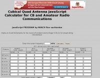 Cubical quad antenna calculator in java script let you calculate elements size and spacing in inch and meters.
 -
 Details the construction of a **multiband vertical** antenna, specifically designed for stealth operation in a rented property, covering 80m, 60m, 40m, and 30m. The author, N3OX, leverages a 12m Spiderbeam telescoping fiberglass pole as the primary support, noting its sturdiness compared to typical fishing rods while remaining light enough for quick deployment and takedown. The radiating element is a 14 gauge Flex-Weave wire, attached to the pole's top with a rubber grommet, and fed by 27 bare 18 gauge radials spread across a 40-foot square backyard. N3OX describes the impedance matching solution, opting for custom-built L-networks over a remote tuner to enable fast bandswitching. Using an MFJ-259B and EZNEC modeling, base impedances were measured and component values calculated with G4FGQ's L_TUNER and SOLNOID_3 programs. The 80m coil is wound on a 3.5-inch PVC form, while the 30m, 40m, and 60m coils are air-wound, self-supporting #10 wire. Variable capacitors are incorporated for 40m and 30m shunt elements, with the 60m impedance matched by a series inductor. The project includes a **servo-controlled** homebrew band switch, utilizing a two-pole 12-position ceramic wafer switch for remote operation, addressing the limited 80m bandwidth. The entire matching network is housed in a weather-resistant shelter constructed from lumber and aluminum flashing. N3OX reports good DX results at 100W, estimating the total cost between $150 and $250, depending on existing parts.
 -
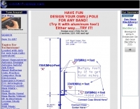 Enter the operating frequency and calculate dimensions of your jpole antenna
 -
 calculates the dimensions and spacings of the elements needed to build a log periodic antenna, given tao, sigma and the lower and upper cutoff frequencies.
 -
 A JavaScript to calculate the dimensions for a seven element Yagi-Uda Antenna
 -
 Calculate eh antenna components dimension with this online form
 -
 An efficient program to calculate dimensions of coax dipoles, or bazooka antennas considering velocity length of different coax cables. Express dimensions in feet/inch and meters/cm. Freeware by VE3SQB
 -
 Calculates resonant frequency of a loop antenna, correcting for distributed capacitance.
 -
 Guide to calculate effective gain of antennas
 -
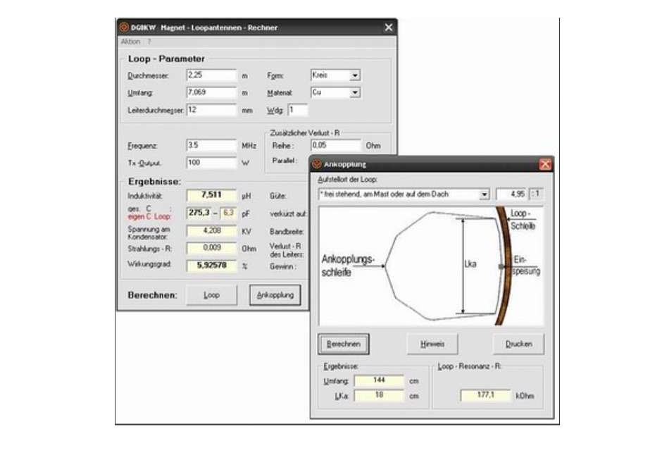 Magnetic loop antenna calculator and loop antenna design program for windows let you calculate dimensions for magnetic loops antennas, in german
 -
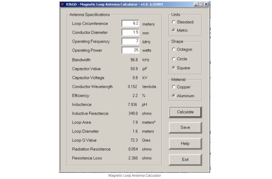 Free windows program to calculate magnetic loop antenna.This small loop antenna calculator allow to determine capacitance and voltage based on Loop circumference, desired resonant frequency, conductor diameter and the operating power
 -
 Quagi antenna design, this little windows application let you calculate dimensions of elements and spacing of a quagi antenna. Freeware by VE3SQB
 -
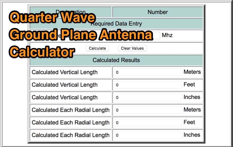 Amateur quarter wave ground plane antenna calculator, calculate vertical and radial length
 -
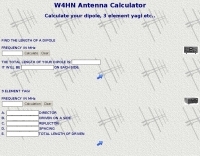 Calculate your dipole, 3 element yagi and a simple dipole
 -
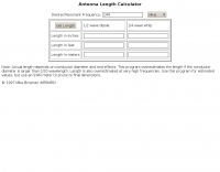 Input the desired resonant frequency and it will calculate lenght in inches feet and meters
 -
 Inverted V antennas is a dipole with the center raised on a mast and the endpoints near ground. Calculate dimensions online.
 -
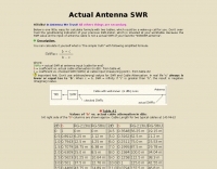 Easy for calculate formula which could be a wake-up call for you. The SWR value at the input of antenna cable is not a actual SWR of your favorite antenna.
 -
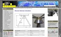 Calculate dimension for discone antennas online
 -
 This PDF document, authored by KT4QW in October 2004, details the construction and modeling of a dual-band, horizontally polarized hanging rectangular loop antenna for **10 and 17 meters**. The design, adapted from *The ARRL Handbook*, utilizes _NEC4WIN95_ software for scaling and optimization, targeting a 50 ohm feedpoint impedance. The resource includes a bill of materials, step-by-step construction instructions, and a discussion of the antenna's radiation characteristics. It presents NEC-generated elevation and azimuth patterns, comparing the loop's performance to a half-wave horizontal dipole at the same height and frequency. The 17-meter element is centered at 18.140 MHz for low SWR across the phone band, while the 10-meter element is centered at 28.500 MHz. Construction involves 14-gauge stranded copper wire and Schedule 40 PVC spreaders, with the total wire length calculated by the formula: Length in feet = 1005/MHz. The feedpoint impedance can be adjusted by modifying the rectangular aspect ratio. The document specifies hoisting the antenna to at least a half-wave above ground for testing. It notes that a balun was tested and found to have no measurable effect on SWR or radiation characteristics. A 2-meter scale model is presented to illustrate the physical design, and a "rotator" string is incorporated for directional adjustment up to 90 degrees.
 -
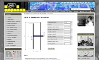 Calculate dimension for HB9CV directional antennas
 -
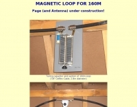 Pictures and calculated values for this home made magnetic loop antenna for the 160 meters band by HB9MTN
 -
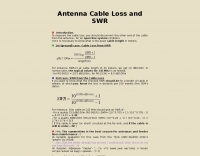 Calculate Cable Loss from SWR and reverse. Text file with only two simply formulas
 -
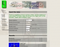 Calculate design for a quadrifilar helicoidal antenna
 -
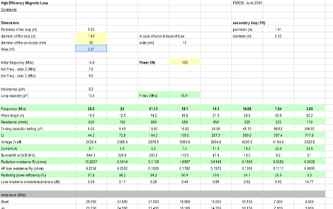 Excel spreadsheet that help calculating dimensions of a high efficiency magnetic loop antenna for HF bands. Giving in input the loop perimeter, loop diameter and loop conductor will calculate electric characteristics, bandwidth, and efficiency
 -
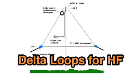 Planning and modelling Delta Loop antennas for all the ham radio HF bands include calculated wire lengths at each mid-band
 -
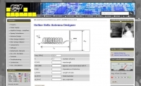 Online helix antenna designer, calculate size of helix antennas online
 -
 Various publications through the years have shown how the SWR measured on a shorted (or open) feed line can be used to calculate feed line attenuation
 -
 The ZS6BKW antenna, a popular multiband wire antenna, offers improved band matching compared to the traditional G5RV. This construction guide details the process, beginning with specific dimensions: 13.11 meters (43 feet) for the 450-ohm ladder line and initial dipole arm lengths of approximately 14.8 meters each. It emphasizes the critical role of an _antenna analyzer_ for accurate tuning, particularly for determining the velocity factor of the ladder line and achieving a 1:1 impedance match. The article outlines the materials required, including a 1:1 current balun, 450-ohm window line, wire for the dipole arms, and a 50-ohm non-inductive resistor for testing. It provides a step-by-step procedure for cutting the ladder line to its electrical half-wavelength, explaining how to calculate the velocity factor using measured and free-space frequencies. For instance, a measured 50-ohm impedance at 12.54 MHz with a calculated free-space half-wavelength frequency of 11.44 MHz yields a velocity factor of 0.91. Final adjustments involve hoisting the antenna to its operational height and fine-tuning the dipole arm lengths to achieve optimal SWR, specifically targeting 14.200 MHz. The _ZS6BKW_ design is noted for its performance on 80m, 40m, 20m, 10m, and 6m, though it is not optimized for 15m operation. The author, _VK4MDX_, shares practical tips for durable construction using stainless steel wire and cable clamps.
 -
 Demonstrates the construction and measurement of a single-turn HF receiving loop antenna, built from common materials like electrical conduit and lamp cord. The resource details the physical dimensions, including a 4-meter circumference, and calculates the theoretical inductance at approximately _6.4 uH_. It outlines a method for determining resonant frequencies across the 4-17 MHz range using a _C Jig_ and a _VR-500 receiver_, coupling the loop with a ferrite ring. The article also discusses the impact of receiver coupling on the loop's Q factor, noting a degradation in sharpness due to the transformer's reflected impedance. Analyzes the observed resonant frequency patterns, highlighting an unexpected rise in the loop's effective inductance at higher frequencies, particularly above 13 MHz. While some increase is attributed to distributed capacitance, the rate of rise suggests further investigation. The experimental setup provides practical insights into the challenges of maintaining high Q in simple receiving loops and offers a comparative reference for other homebrew antenna projects, such as those by _VK2TPM_.
 -
 Calculate EH Antenna, 20m 40 80m. Fotos, Original eh antenna building.
 -
 Over 1,000 stations in approximately 60 countries were worked using this modified twin-lead folded dipole, demonstrating its effectiveness with just 4 watts on 20 meters. This design, adapted from an ARRL Handbook concept, eliminates the shorting strap found in traditional folded dipoles, simplifying construction while maintaining performance. It utilizes readily available 300-ohm TV antenna feeder ribbon, making it a cost-effective solution for radio amateurs. The antenna's robust construction allows it to handle up to 100 watts without issues, even without a **balun**. The inclusion of a variable trimmer capacitor at the stub provides flexibility for tuning across different frequencies within a band, a practical feature for operators using transceivers like the Icom 735. Formulas are provided to calculate the precise dimensions for any desired operating frequency, enabling customization for various **HF bands**.
 -
 Calculate online, ERP in dB and dBi given PWR Frequency Coax lenght and type and antenna type
 -
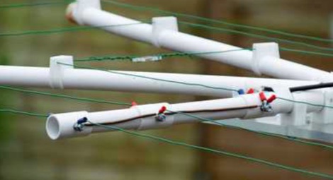 A PDF presentation of a home made moxon antenna for 50 MHz 70 MHz and 144 Mhz. The project is mainly out of surplus plastic Plumbing pipes and clips etc, and also details of how the dimensions were calculated.
 -
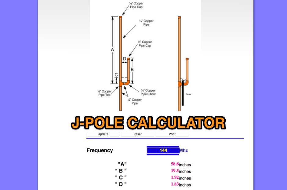 An online J-Pole antenna calculator that need just to input the frequency and calculates in inch size of each element
 -
 This page allows you to calculate in the most accurate way high-Q inductor coils.
 -
 Use this online calculator to determine the length of a full-wave loop antenna from the frequency. Both metric and English units of measurement are supported. Quarter-wave matching section lengths are also calculated.
 -
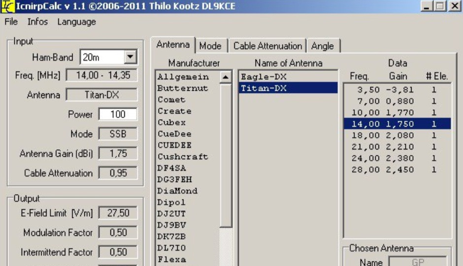 ICNIRP is a calculator software that allows you to determ safety distances for many know amateur radio antennas with respect to ICNIRP limits developed by DL9KCE
 -
 Operating magnetic loop antennas requires careful consideration of RF safety, particularly regarding near-field magnetic field intensity. This resource presents calculations for magnetic field strength (H-field) at various distances from a magnetic loop, emphasizing that the H-field is significantly higher than the E-field in the near-field region due to the inductive nature of the radiating element. It provides specific formulas and examples for determining safe operating distances based on power levels and loop dimensions, crucial for compliance with RF exposure limits. The analysis compares calculated H-field values against FCC and ICNIRP maximum permissible exposure (MPE) limits for controlled and uncontrolled environments. It demonstrates that even at QRP power levels (e.g., 5W), the H-field can exceed MPE limits within a few feet of the antenna, necessitating greater separation distances than often assumed for electric field considerations. The practical application of these calculations helps amateur radio operators configure their stations to ensure personnel safety and regulatory compliance when deploying compact, high-Q magnetic loop antennas.
 -
 This simple antenna modelling windows software by F5IMV wil calculate a dipole,extended double Zepp,G5RV, ZS6BKW and many other wire antennas by F5IMV
 -
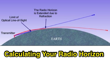 The range and coverage of your VHF transceiver will be limited to your radio horizon. How to calculate the visual horizon and how to determine the Radio Horizon
 -
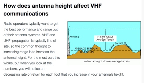 How to calculate range for a VHF antenna with a simple formula and how to increase VHF coverage.
 -
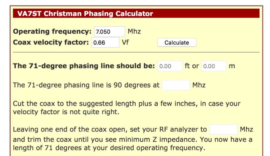 Calculate vertical array pahse antenna accorting to the Christman technique
 -
 1.5 dB of matched line loss can be calculated for a given transmission line using this online tool, which employs a model calibrated from empirical data. The calculator allows radio amateurs to input specific transmission line types, such as _RG-8_ or _RG-58_, and then determine the expected signal attenuation. This is crucial for optimizing antenna system efficiency and understanding power delivery to the radiating element, especially for HF and VHF operations where feedline losses can significantly impact performance. Beyond matched loss, the calculator also provides an estimate for mismatched loss if the Standing Wave Ratio (SWR) is specified. This feature helps operators quantify the additional power loss due to impedance discontinuities between the transceiver, feedline, and antenna, which is a common concern in amateur radio installations. Accurate loss calculations are vital for effective station design and for predicting actual radiated power. The tool's utility extends to various operating scenarios, from fixed station setups to portable deployments, aiding in the selection of appropriate feedline lengths and types to minimize signal degradation. Understanding these losses is a fundamental aspect of maximizing the effectiveness of any amateur radio antenna system.
 -
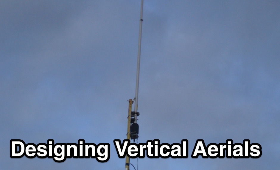 If you want to design vertical antennas you can find all theory and formulas used to model a vertical aerial calculating capacitance, reactance, building the inductor and calculating resistances. Includes an excel spreadsheet to calculate efficiency.
 -
 Inches and meters Javascript Wavelength Calculator allow to input a frequency in MHz and calculate wavelenght in several units considering also fractions of wavelenght and the velocity factor. Includes an usefull inch to meter converter
 -
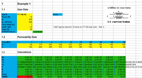 This EXCEL Program Worksheet calculates the common-mode impedance of a 1:1 Guanella (current) balun which is placed at the feed point of a balanced antenna system fed via coax.
 -
 ICNIRPcalc allows you to calculate safety distances for many know amateur radio antennas with respect to ICNIRP limits by DL9KCE
 -
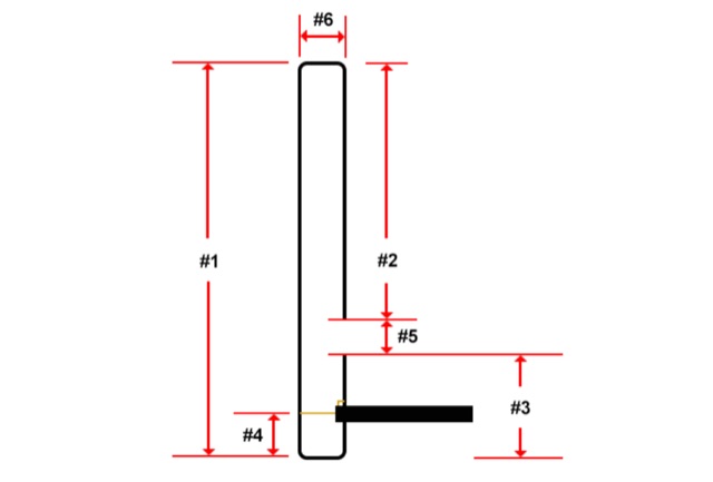
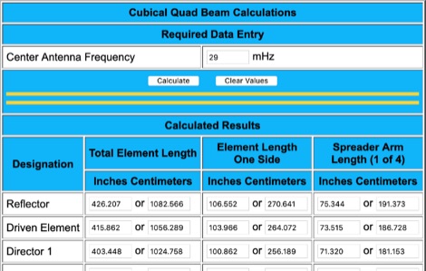 Cubical Quad Antenna On-line Calculator helps on defining the size of each element and spreader. Simply give the resonating frequency and it will calculate size of each element.
 -
 Easy to use online Slim Jim antenna calculator. Input your frequency to automatically calculate the lengths of the different antenna parts.
 -
 The Tri-pole antenna, a clever modification of a standard dipole, allows for dual-band operation by integrating a third element. This design effectively shortens the overall dipole length by 10 to 20 percent, simplifying antenna rotation and offering a compact footprint. KK4OBI's article delves into the operational principles, using a 6 and 10-meter Tri-pole as a primary example, and provides comprehensive instructions for constructing any Tri-pole antenna within the 6 to 15-meter range. Key to the Tri-pole's performance is its off-center feed, necessitating a common mode choke at the feed point for optimal tuning and reduced noise. The author outlines a methodical approach to determining element dimensions, starting with a vertical element frequency calculated as 0.47 times the sum of the desired upper and lower band frequencies. This calculation, along with K-values derived from trend lines, guides the initial lengths for the horizontal arms, demonstrating how a 10m-6m Tri-pole can achieve a total horizontal length 78% shorter than a conventional 10-meter dipole. Tuning and balancing are critical, with the article detailing adjustments to arm lengths and the vertical element to achieve balanced SWR values, as validated through 4NEC2 simulations. Radiation patterns are analyzed at various elevations, showing gains around 5.7 dBi and favorable take-off angles for DX contacts. Construction details specify aluminum tubing dimensions, U-bolts, and an SO-239 connector, emphasizing the importance of a ferrite-based choke for wideband operation.