Search results
Query: antenna connector
Links: 104 | Categories: 1
-
 This resource provides a detailed guide on constructing a J-pole antenna specifically for the 2 meter band, which is popular among amateur radio operators. The article outlines the materials needed, including various sizes of aluminum pipes and PVC, as well as the tools required for assembly. It emphasizes the simplicity and effectiveness of the J-pole design, making it an ideal choice for newcomers to amateur radio. The instructions are straightforward, allowing users to build the antenna in less than an hour, and include tips for tuning the antenna for optimal performance. In addition to the construction details, the resource includes practical advice on the assembly process, such as how to cut and join the pipes, as well as how to mount the SO239 connector. The author shares personal experiences and insights on achieving a low standing wave ratio (S.W.R.) and suggests modifications for creating bi-band or tri-band J-pole antennas. This comprehensive guide is enriched with photographs that illustrate the construction steps, making it easier for users to follow along and successfully build their own J-pole antenna.
 -
 This guide provides step-by-step instructions for constructing a tin can waveguide antenna, commonly known as a cantenna, for enhancing WiFi signal range. The project is budget-friendly, costing under $5, and utilizes easily accessible materials like a food can and basic electronic components. The design is suitable for 802.11b and 802.11g wireless networks, operating within the 2.4 GHz frequency range. To start, gather the necessary parts including an N-Female chassis mount connector, nuts, bolts, and a suitable can. The assembly process involves drilling holes in the can for the connector and mounting the probe. The guide emphasizes the importance of can dimensions and placement for optimal performance, encouraging experimentation for best results. This project is ideal for amateur radio operators and DIY enthusiasts looking to improve their wireless connectivity without significant investment. Safety precautions are advised, as the author does not hold electrical engineering credentials. Users are encouraged to take responsibility for their equipment and ensure proper assembly. With this simple yet effective antenna, users can extend their WiFi coverage and enjoy enhanced connectivity.
 -
 Sixty-four years of operating experience inform Glynn E. "Buck" Rogers Sr., K4ABT's, insights into the J-Pole antenna, which he describes as a direct descendant of the _Windom_ or _ZEPP_. His first article on the J-Pole appeared in HRC magazine in 1958, and he has since published numerous pieces in publications like CQ Magazine, consistently referring to the J-Pole as a Windom with a folded-back short section forming the parasitic element. He emphasizes that both the Windom and J-Pole are powerful multi-band antennas, performing exceptionally well at harmonics of their fundamental design frequency, and advocates for 50-ohm coaxial cable with a _BALUN_ at the feed-point to avoid RF energy losses. K4ABT details the J-Pole's features, noting its ease of erection, lack of radials, low angle radiation, greater bandwidth, and immunity to terrestrial noise. He highlights its suitability for local nets and distant repeaters, claiming more gain and durability than most ground planes, and its ability to meet stealth antenna requirements. The guide provides specific dimensions for 2-meter (145.000 to 146.000 MHz) and 6-meter (50.500 to 51.500 MHz) J-Pole antennas, including measurements for the long driven element, short tuning stub, and spacing. The construction section illustrates a modified feed technique using an SO-239 chassis-mount coax connector soldered into a copper tee, deviating from the usual hose clamp method. The author also discusses the use of _EMT_ (electrical metallic thin-wall conduit) as an alternative to copper in earlier days. He cautions against building a 75-meter J-Pole due to its impractical length, reinforcing the antenna's optimal application for VHF and UHF bands.
 -
 A 1/4 wavelength resonator design for dual-band VHF/UHF operation is presented, focusing on a robust mobile antenna construction. The design prioritizes stability against environmental influences over raw gain, making it suitable for general use rather than marginal signal areas. It details the antenna's two sections: a UHF-resonant lower conductor and an upper coil functioning as an RF choke for UHF and an inductance enhancer for VHF, forming a resonant circuit. Detailed mechanical structure and material considerations are provided, including the use of a PL-259 plug base, 2mm copper rod, and PVC faucet tube for the coil form. The guide outlines a precise construction procedure, from soldering the copper rod to the PL-259 to winding the 22 SWG laminated wire for the VHF section. Tuning involves careful cutting of the UHF section and adjusting the coil length and pitch for VHF, using a reflectometer and temporary ground planes. Furthermore, the resource describes converting the mobile antenna for base station application by constructing a dual-band ground plane system. This involves using electrical conduit, EMT connectors, SO-239 sockets, and a 4-inch round-pan with threaded stainless steel rods as ground elements. Practical test results indicate optimal lengths of **70mm** for UHF and **350mm** for VHF ground elements, with a recommendation to cut rods with _30mm_ extra length for fine-tuning.
 -
 The **DF9CY Three-Element Antenna for 28 MHz** details the modification of a commercial PAN International CB antenna to optimize its performance for the 10-meter amateur radio band. This resource provides specific design parameters, including a design frequency of 28.300 MHz, a usable bandwidth of 600 kHz, and a return loss better than 20 dB centered at 28.270 MHz. It also specifies a gain exceeding 7.5 dBi and a front/back ratio greater than 20 dB. The feeding mechanism utilizes a **gamma match**, with setup instructions provided for its positioning. Modifications involved shortening each element's end by 40 mm, a straightforward process due to existing screw holes. The author also recommends replacing the original screws with V2A stainless steel hardware to prevent oxidation and upgrading the SO239 connector to an N-connector for improved reliability. EZNEC simulation files are available, showing azimuth and elevation diagrams with good front-to-back ratio and around 10 dB vertical attenuation. The antenna has been in service since October 1998, demonstrating good performance with 90 watts and even 750 watts, facilitating contacts with all continents from a modest 9-meter height.
 -
 Details the construction and optimization of antenna systems for amateur radio satellite operations, focusing on practical, homebrew solutions for VHF/UHF bands. It covers building _groundplane antennas_ from salvaged materials, recycling old beam antennas into new configurations like a 2-meter crossed yagi, and constructing a 10-meter horizontal delta loop. The resource also explains antenna matching techniques, including folded dipole driven elements and quarter-wave transformers, along with the importance of accurate SWR measurements and minimizing coax loss. Demonstrates how to achieve a **1:1 SWR** by carefully trimming elements and adjusting radial angles on groundplane antennas. It provides insights into selecting appropriate coax and connectors, highlighting the benefits of Belden 9913 for low loss and the proper installation of _N-connectors_. The article also addresses RFI mitigation from computer birdies and presents a design for a silent triac antenna control circuit, offering practical solutions for common satellite station challenges.
 -
 A self-supporting vertical antenna design for stationary-mobile HF-VHF operation is presented, emphasizing ease of construction with common materials like a fiberglass fishing rod and PVC pipe. The design focuses on creating a set of no-tuner monoband radiators for bands such as **2m**, **6m**, 10m, and 12m, with an overall radiator support length of 3.3m. The construction process details the assembly of the antenna base using a magnetic mount, PL-259 connector, and PVC pipe sections, which then supports the telescopic fishing rod. Radiator extensions are cut to achieve quarter-wave resonance on specific bands, with detailed instructions for 6m (50-51 MHz), 10m (28.5 MHz), and 12m (24.9 MHz). For lower HF bands like 15m, 17m, and 20m, the design incorporates base-loading coils, with specific turn counts provided (e.g., 21 turns for 20m). The project also suggests using an _antenna analyzer_ for precise tuning of extensions and coils, moving beyond theoretical values to achieve optimal performance. The author, _IK1ZYW_, notes that for 80m and 160m, the antenna becomes less efficient as a vertical, suggesting alternative configurations like an inverted-V dipole or asymmetrical inverted-L.
 -
 The _Morgain_ antenna for 40/80 meters is a straightforward and cost-effective wire antenna design, requiring careful tuning for optimal performance across two bands with low SWR. Construction involves creating 12 cm PVC spacers with three holes for wire insertion, along with larger terminals for anchoring and connector housing, which should be sealed with silicone. The provided measurements detail the specific lengths for the antenna elements, crucial for achieving resonance on both 40m and 80m bands. Tuning the Morgain antenna necessitates fabricating four wire segments with pins to temporarily connect and adjust the bridging points symmetrically for both 40m and 80m. This iterative process, though time-consuming, ensures the antenna functions effectively for decades once the precise connection points are soldered and protected. The design emphasizes ease of construction and long-term stability, making it a practical solution for hams seeking a dual-band wire antenna.
 -
 Hong Kong's only full-service amateur radio store. Full line of Amateur Radio and Two-way equipment and accessories from companies such as Yaesu, Icom, Kenwood, Motorola, MFJ, Alinco, Diamond, AOR and many, many more. Knowledgeable staff with many years of experience in the radio business TAX-FREE shopping (no sales, VAT, GAT or other taxes) HF, VHF, UHF transceivers, receivers, walkie-talkies, antennas, antenna tuners, coax and connectors
 -
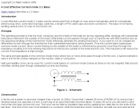 A cost effective current-mode 1:1 balun can be constructed from a length of coax and a rod typically used for a broadcast antenna loop-stick, some electrical tape, cable ties, a length of PVC water-pipe and some connectors.
 -
 Presents a catalog of **QRP** transceivers, antenna tuners, and related accessories for amateur radio operators. The product line includes the ZM-2 antenna tuner, designed for efficient impedance matching across HF bands, and the NW-series QRP transceivers, offering low-power CW operation. Additionally, the site details various ladder line insulators and specialized connectors, emphasizing robust construction for field deployment and home station use. Each product listing provides specifications, operational parameters, and pricing information. Compares the features of different **QRP transceiver** models, such as the NW-40 and NW-20, highlighting their respective band coverage and power output capabilities. The ZM-2 tuner's performance is detailed with typical SWR reduction figures for various antenna types, demonstrating its utility for portable and fixed stations. Customer testimonials and product images illustrate the practical application and build quality of EMTECH's offerings, providing insights into their durability and ease of integration into existing amateur radio setups.
 -
 Presents a detailed construction guide for a 2-element _Moxon rectangle_ antenna optimized for the 10-meter band, designed by L. B. Cebik, W4RNL (SK). This resource demonstrates how to build a compact beam antenna using readily available hardware store aluminum tubing, fitting within a 12-13 foot width. It highlights the antenna's performance characteristics, including a gain comparable to a 2-element Yagi (11+ dBi) and a front-to-back ratio exceeding 20 dB between 28.3 and 28.5 MHz, with an SWR below 2:1 across the entire band. The design emphasizes direct 50-ohm coax connection without a separate matching system, though a 1:1 choke _balun_ is recommended. The guide provides practical advice on element construction, corner fabrication using L-stock or radius-bent tubing, and the critical side-to-side length adjustment for SWR optimization. It details the feedpoint assembly using a chassis-mounting coax connector and discusses element-to-boom plate options, including spar varnished plywood or LE plastic. The author's experience with a test model on a 20-foot mast confirms stable feedpoint characteristics and excellent performance even at lower heights. The document also includes insights into the antenna's free-space azimuth patterns, noting a broad forward lobe and significant front-to-back rejection. It contrasts the Moxon with traditional Yagis, positioning it as an effective, home-buildable alternative for compact sites or _Field Day_ operations, particularly beneficial during periods of increased 10-meter activity.
 -
 Presents a practical approach to constructing a portable, lightweight antenna support structure, ideal for field operations or temporary installations. The design utilizes readily available PVC pipe sections, allowing for a total height of **20 feet** and a transportable weight of **25 lbs**. Detailed material lists specify various PVC pipe diameters and lengths, along with couplers, tees, and elbows, facilitating a modular assembly that can be easily disassembled for transport. Accompanying the tower design, the resource also outlines the construction of a _MicroVert_ antenna, including formulas for radiator length, capacitance, and inductance. It provides guidance on creating a current balun using ferrite beads or a coax coil, and calculating counterpoise length for optimal performance. The antenna section includes a schematic diagram illustrating the connection of the SO-239 connector and counterpoise.
 -
 Antennas, books, rf parts, tubes,connectors and cables and many accessories at RF parts.
 -
 Manufacturer of communications antennas, bandpass filters, RF combiners, receiver multicouplers, diplexers, duplexers, RF connectors, RF circulators, RF isolators, RF couplers and SWR meters
 -
 Technical reference about Accessories, Amplifiers, Antennas, Cable and Connectors, Filters, Geography, Grounding, Gunk, Matching Networks, Projects, Propagation Info Radios, RFI/EMI, Rotors, Station Setup, Towers.
 -
 Constructing a **2-meter** J-pole antenna from readily available copper plumbing components offers a robust and cost-effective solution for VHF operation. This design, dubbed the "Plumber's Delight," functions essentially as a half-wave dipole fed by 50-ohm coax via a **gamma match**. It incorporates a quarter-wave copper tubing support, which, when affixed to a metal mast or tower, enhances forward power in the direction of the radiating elements. The original configuration utilized a small ceramic trimmer capacitor for the gamma match, suitable for up to 10 watts. A subsequent modification replaced this with a 50 pF variable capacitor housed in a plastic enclosure, accommodating higher RF power and improving weather resistance. The antenna elements are secured using a copper "T" fitting, and an SO-239 connector mounts directly to this fitting. Performance includes gain away from the support mast, and tuning is straightforward by adjusting the gamma match capacitor for a 1:1 SWR. The total cost for materials, excluding the capacitor and coax, can be under $10.
 -
 Details the construction of a portable _Moxon_ antenna optimized for the 2-meter band, utilizing readily available materials like 6.5 mm aluminum elements and a 15x15 mm TV boom. The design emphasizes ease of assembly and portability, making it suitable for field operations. Performance specifications derived from MMANA modeling indicate a forward gain of **6.3 dBi** and a front-to-back ratio of **15 dB**. Lateral attenuation is reported at 40 dB, with a minimum SWR of 1.1 at 144.300 MHz, confirming efficient operation within the target frequency segment. The antenna is lightweight at 500 grams, quickly assembled in approximately two hours, and disassembles into a compact 40x15x8 cm package. Direct feeding with RG-58 C/U or KX-15 coaxial cable via a BNC connector simplifies deployment.
 -
 Autotena, a Taiwanese manufacturer, offers a diverse product line focused on RF communication antennas and related accessories. The resource details various antenna types, including **4G/3G LTE wideband high-gain low-profile antennas**, land mobile wideband antennas, fiberglass omnidirectional designs, and GPS mobile and marine antennas. Specific amateur radio offerings include NMO VHF load coil gain antennas, VHF whip gain antennas with PL-259 connectors, and UHF NMO mount antennas with 3dB/5dB gain. The company also produces antennas for CB and 10-meter amateur bands, such as aluminum broadband 26-30MHz antennas and big copper coil broadband 26-30MHz antennas. Additionally, the site showcases **RF amplifiers** for CB, HF, VHF, and UHF bands, including professional-grade base station amplifiers with 100% EIA duty cycle. Handheld antennas, PL-259 type mobile antennas, magnet mount antennas, and external CB speakers are also presented, alongside various mounting kits and cable assemblies.
 -
 Over 75 years of engineering expertise underpins Bird Electronic's offerings in RF power measurement, critical for maintaining peak performance in amateur radio stations and professional communication systems. The company specializes in a range of test equipment, including wattmeters, SWR meters, and antenna analyzers, essential for optimizing antenna systems and ensuring efficient power transfer. Their product line extends to various RF components such as filters, cables, and connectors, all designed to meet stringent technical specifications for reliability and accuracy across diverse frequency bands. Bird Electronic's instruments, like the _Bird 43_ Thruline Wattmeter, are widely recognized for their robust construction and precise measurement capabilities, providing hams with confidence in their station's operational parameters. These tools enable accurate assessment of forward and reflected power, SWR, and modulation characteristics, which are vital for troubleshooting and maximizing radiated power. The company's commitment to innovation ensures that its products remain relevant for modern RF challenges, from HF through microwave applications, supporting both traditional analog and advanced digital modes.
 -
 It is very easy to create a simple 1/2 wave dipole, all you need is some lengths of wire such as the core of some mains flex or even a straightened out metal coat hanger, some co-ax cable and a connector for your scanners antenna input
 -
 Constructing a compact UHF Moxon antenna for portable radio or TV applications demands a small, easily transportable aerial. This project focuses on a straightforward build method rather than a specific frequency design, leveraging _MoxGen_ software by AC6LA to derive precise dimensions. The author's approach utilizes an epoxy printed circuit board as the support, with traces drawn by a special felt-tip pen for soldering the antenna elements after an etching bath. For high-frequency work, particularly in the GHz range, the choice of insulating material is critical; the article emphasizes the necessity of quality UHF or SHF-grade insulation. A standard SMA connector is integrated, with one element making electrical contact via the nut and the other soldered to the central pin. This ensures a robust feedpoint for the coaxial cable. The coaxial cable, fitted with its connector, is threaded through a 12mm PVC tube that functions as a mini-mast. This tube also defines the antenna's forward direction, which should be aimed at the target signal. A sanitary clamp at the base of the tube secures it to a photographic tripod via its 7mm thread, providing a stable and portable mounting solution.
 -
 The 10-meter EH Antenna document details the construction and performance of a specific EH antenna design for the 10-meter band. It describes the integration of an L+L balanced matching network, a key component for impedance transformation, and highlights the addition of a tuned coaxial trap. This trap, consisting of 8 turns of RG58 coax wound around PVC tube and resonated at 29 MHz with a 10 pF capacitor, effectively inhibits common-mode current on the feeder, stabilizing antenna tuning. The resource presents a circuit diagram in Figure 1 and assembly details in Figure 2, illustrating the use of PVC plumbing tube as host material for dipole cylinders made from recycled aluminum tubing. It also explains the fabrication of capacitor stators and slider sections from thin aluminum tubing. The author, Lloyd Butler VK5BR, discusses initial challenges with feeder interaction and how the tuned trap resolved these issues, leading to stable tuning. Limited backyard tests indicate that the antenna, with the trap fitted close to the input connector, might exhibit similar field strength for both low and high angle transmission, suggesting a potential skewing of the signal. The document references previous articles by VK5BR in "Amateur Radio" for further operational details of the matching network and trap functionality.
 -
 Constructing a Lindenblad antenna for 137MHz NOAA satellite reception involves specific design considerations for optimal performance. The resource details the use of 4mm galvanised steel fencing wire, 300-ohm television ribbon cable, and wood/plastic components for the antenna structure. Key dimensions for a 137.58MHz-resonant antenna are provided, derived from the ARRL Satellite Handbook, specifying s, l, w, and d as 42, 926, 893, and 654mm respectively. The antenna is designed for Right Hand Circularly Polarised (RHCP) signals, requiring the four folded dipole elements to be tilted clockwise by 30 degrees. A significant aspect covered is impedance matching between the antenna's 75-ohm impedance and a typical 50-ohm receiver input. A twelfth-wave matching transformer, constructed from 117mm sections of 50-ohm RG-58 and 75-ohm RG-59 coax with a 0.66 velocity factor, is described. The article also addresses coaxial cable and connector selection, recommending 75-ohm Type-N connectors for RG-6 cable in professional setups and F56/F59 connectors for general use, while strongly advising against PL-259/SO-259 connectors for VHF. Strategies for mitigating Radio Frequency Interference (RFI) are discussed, including antenna placement to shield from local TV transmitters and the use of commercial or DIY band-pass filters, such as cavity resonators or helical notch filters, along with ferrite chokes on coaxial cables. Antenna orientation is explored, noting the Lindenblad's 'cone of silence' directly overhead and its maximized sensitivity towards the horizon. An experimental vertical tilt of 90 degrees is presented as a method to improve overhead reception and reduce interference from strong horizontal signals, particularly relevant in high RFI environments like the Siding Spring Observatory site.
 -
 Antenna manufacturer from Poland, produce dipole wire antennas, W3DZZ FD4 Windom and long wires, baluns, dealer for toroids and connectors managed by Leszek Mlynarczyk SP1BKS
 -
 The K0RWU 75-meter mobile antenna design features a 7.5-foot overall length, incorporating a 2.5-foot loading coil wound with #20 enamel wire on a 1/2-inch fiberglass rod, subsequently covered with 1/2-inch shrink tubing to increase diameter to 3/4 inch. This configuration achieved resonance at 3965 kHz with a 5-foot stainless steel whip. The antenna integrates a matching transformer, identified by larger turns near the PL259 connector, and is constructed using a modified Radio Shack CB antenna base. Construction involves drilling and epoxying a 1/2-inch fiberglass rod into a PL259 connector, feeding #20 enamel wire through the rod, and winding 17 turns of #18 matching coil wire between the PL259 sleeve and the center feed point. The main loading coil fills the 2.5-foot rod section. The design allows the antenna to bend for garage clearance and emphasizes maintaining a 50-ohm feed impedance to prevent vehicle electrical damage. The author also discusses experiences with a Yaesu ATAS-100 motorized antenna and a 10-meter antenna project, noting issues with auto couplers and the ATAS-100's performance on 17 meters. Future modifications considered include adding a small servo for band spreading and increasing the fiberglass rod length for a 3-foot loading coil to improve bandwidth. The antenna's sharp tuning, between 3960 kHz and 3970 kHz, necessitates careful adjustment of coil turns for optimal VSWR.
 -
 DAVIS RF Co. has been in the business of supplying the staples of wire antennas for over 30 years. DAVIS RF Co. supply all coax cables, all connectors, ladder line, rotar control cable, insulators, and we have the largest selection of wire for wire antennas. DAVIS RF Co. is the designer and trade mark holder, and primary source for Bury-Flex Tm low loss coax cable. PolyStealth Tm high strength PE insulated antenna wire, and Flex-Weave Tm wire
 -
 Details the construction of a **17-meter Moxon Rectangle** antenna, specifically engineered for mounting on a mast beneath an existing beam. The design incorporates insulated wire calculations (0.95804 x generator length) to compensate for velocity factor differences, utilizing readily available materials such as crappie poles for elements, PVC for the boom and mast, and a Budwig HQ-1 dipole connector for the 50 Ohm coax feed. The project outlines a step-by-step assembly process, including mast construction from PVC T-connectors and pipe, element fabrication from crappie poles, and securing elements to prevent droop. Initial testing demonstrated an SWR of 1.3:1 on 17 meters, achieving a 5-8 signal report into Texas with 100 watts. Subsequent reinforcement and elevation of the antenna resulted in a 15 over 9 report from Florida. Comparative testing against an 88-foot center-fed Zepp antenna indicated superior performance, with the Moxon consistently outperforming the Zepp and receiving signals the Zepp could not. A notable DX contact with JA8NFV in Hokkaido, Japan, yielded a 5-9+ signal report both ways using 100 watts.
 -
 Unique and Hard-to-Find accessories for Amateur Radio. Featuring Plasti Dip products, DK9SQ Masts, Wire Antennas, AEA Antenna Analyzers and RF Connectors too!
 -
 HD Communications Corp specializes in **RF and microwave amplifiers** engineered for demanding communication, defense, and industrial applications. Their product line includes precision-built, high-power solutions, along with RF connectors, filters, HF cables, and various accessories. The company also supplies tower hardware, valves, and tubes, catering to a broad spectrum of radio frequency infrastructure needs. Beyond amplifiers, HD Communications offers a range of **RF filters**, including low-pass filters, antenna filters, and solutions for RFI/TVI mitigation. Their inventory encompasses essential components like coaxial cable and various connector types, supporting both amateur radio and professional installations. The company operates as a manufacturer and vendor, providing direct sales of its specialized RF products.
 -
 Demonstrates the design and construction of a 9-element Yagi antenna for the **70 cm band** (432 MHz), based on the DK7ZB concept. The resource details EZNEC+ calculations for a single antenna, providing gain, sidelobe suppression, and front-to-back ratio figures. It also presents a comprehensive analysis of stacking two such antennas, including optimal stacking distance (1000 mm) and the resulting performance enhancements for the stacked array, such as an increased gain of 17.03 dBi. The article includes detailed drawings, wire file dimensions in millimeters, and azimuth/elevation plots for both single and stacked configurations. Practical construction steps are documented with original photographs, illustrating element mounting, the **28 Ohm matching system** using two quarter-wave 75 Ohm transmission lines, and the critical N-connector wiring. It also covers the iterative process of fine-tuning the driven element length to achieve a return loss of 20 dB, validating the EZNEC+ simulation results with actual measurements.
 -
 A GSM1800 Moxon Square antenna project is presented, detailing its construction using three 1.5mm copper wire pieces for the reflector and dipole elements. The design inherently offers a 50-ohm feedpoint impedance, allowing direct connection to 50-ohm coax without complex matching networks like baluns or gamma matches, which are prone to high attenuation at 1.8 GHz if not precisely built. The resource includes a construction plan, expected **SWR plots**, and **radiation patterns** for the GSM 1800 band, specifically covering the 1710-1785 MHz transmit (red zone) and 1805-1880 MHz receive (blue zone) segments. The SWR remains below 2:1 across the entire GSM 1800 band, with the main lobe consistently achieving 5-6 dBi gain. While the radiation pattern shows some changes across the band, these primarily affect the back of the antenna, maintaining consistent forward gain. Practical considerations for high-frequency operation are emphasized, such as minimizing coax length (e.g., under 1 meter for RG-174) and selecting appropriate connectors like N, SMA, or BNC to mitigate significant attenuation. The article also discusses direct connection to the phone's RF PCB for minimal loss and notes observed signal strength variations with antenna orientation despite crossed polarization at cell sites.
 -
 With over 20 years of experience, Proyecto 4 operates as a specialized ham radio retailer in Madrid, Spain, providing a diverse inventory of transceivers, antennas, and related accessories. The store features popular models like the _ICOM IC-705_ and _ICOM IC-7300MK2_, alongside Yaesu transceivers such as the _FTX-1 Optima_, which delivers 100W on HF and 50W on V/UHF bands. The product range includes mobile and portable antennas, such as the D-Original DX-NR770HB, offering 3 dB gain on 144 MHz and 5.5 dB on 430 MHz, and the Diamond RH-770 with a BNC connector. CB radio enthusiasts can find the Anytone CB SMART II AM/FM transceptor and the Telecom LS145 mobile antenna, rated for 500W and 4 dB gain on 26-30 MHz. Proyecto 4 emphasizes its in-house technical service, inviting customers to visit their laboratory for repairs and technical consultations via sergio@proyecto4.com. The store also highlights customer reviews and offers promotions like Yaesu Cashback, providing savings up to 100€.
 -
 A 2m Moxon antenna project, designed for the 145 MHz amateur radio band, provides a compact, directional solution for VHF communications. This resource details the construction process, specifying materials like PVC pipe for the frame, copper wire for elements, and a SO-239 connector for the feedpoint. The design emphasizes ease of build for hams seeking a gain antenna with good front-to-back ratio for local ragchewing or contesting. The project outlines precise element lengths and spacing, crucial for achieving the desired impedance and radiation pattern. It includes a visual representation of the antenna's dimensions and assembly, allowing for straightforward replication. The Moxon's inherent characteristics offer a practical alternative to larger Yagi arrays, particularly for portable operations or restricted spaces, while still delivering effective directivity and gain.
 -
 A 50-ohm 10W resistor forms the core of this portable QRP antenna, designed by _K0EMT_ for convenient operation on 160m and 80m. The construction involves soldering the resistor to a BNC connector, with one lead to ground and the other to the center conductor, then insulating the assembly. This minimalist design aims to provide a highly portable solution for low-band QRP operations, acknowledging the inherent trade-offs between antenna size and efficiency. Testing with an antenna analyzer revealed low SWR on both 160m and 80m, with a Yaesu FT-817 confirming good matching. While 40m and 30m showed higher SWR, the primary focus remains on the lower bands. The author successfully tested the antenna with **2.5W CW** output, demonstrating its practical application for QRP field operations where ease of deployment is paramount, even if it means sacrificing some **gain** compared to full-sized antennas.
 -
 Located in southern Ontario Canada, supplier for HF VHF antenna kits, aluminium tubing, portable j-pole antennas, lightning suppressors, connectors and adapters
 -
 RFAC Solutions specializes in providing a range of RF components, including various connector types, cable assemblies, attenuators, and filters. Their product line features common connector standards such as SMA, BNC, TNC, N-Type, MCX, and MMCX, essential for reliable RF signal paths in amateur radio and commercial applications. The company also offers high-power VHF amplifiers, catering to needs for signal boosting in specific frequency ranges. Their offerings extend to dust caps and adapters, which are crucial for maintaining the integrity and versatility of RF systems. The focus on supplying components from South Korea suggests a commitment to specific manufacturing standards and supply chain practices. This resource details a vendor's product scope, useful for hams sourcing specific parts for shack builds or antenna projects. Jeff is listed as a contact for inquiries.
 -
 Selecting appropriate cabling for amateur radio installations, whether for antenna feedlines, control lines, or station wiring, is critical for optimal performance and safety. This resource provides access to a manufacturer specializing in a broad range of electronic and electrical cables, including options suitable for various ham radio applications. Their product line encompasses standard and custom cable solutions, designed to meet specific operational requirements for both indoor shack setups and outdoor antenna systems. The company emphasizes _proven quality_ and compliance, with products certified by the Canadian Standards Association (CSA), Underwriters Laboratories (UL), and Intertek (ETL). Their quality management system is registered to _ISO 9001:2015_, ensuring consistent product standards. They offer competitive pricing and utilize AI-logistic tools for reliable on-time delivery, serving customers globally with technical support. Access to detailed technical specifications and an online quote tool is available for registered site members, facilitating precise cable selection for projects requiring specific impedance, shielding, or environmental ratings.
 -
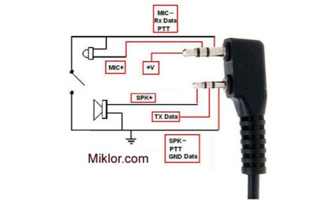 The resource provides specific technical details for Baofeng UV-3R and UV-5R series handheld transceivers, illustrating various hardware configurations. It presents a detailed _speaker microphone pinout_ diagram for multiple brands, including Baofeng, Anytone, Kenwood, and Wouxun, specifying 3.5mm and 2.5mm plug connections for mic, PTT, speaker, and data lines. The page also explains the wiring for dual PTT switching, particularly for the Baofeng UV-82 series, showing how to key either the upper or lower display channel. Furthermore, it offers comprehensive schematics and construction guidance for programming cables, detailing connections for CP2102 USB-UART modules to 3.5mm and 2.5mm plugs, and providing specific configurations for radios like the BTech UV-2501/5001 and QYT KT8900. The content also addresses SMA antenna connections, clarifying SMA Female, SMA Male, and SMA RP types, and discussing issues related to extended antenna threads, suggesting solutions like using a #8 O-Ring to ensure proper contact and prevent transmitter damage. The resource includes a section on troubleshooting erratic charger behavior, attributing issues to poor contact from tension clips and offering a simple fix.
 -
 One point eight MHz to 30 MHz is the operational bandwidth for this 4:1 Ruthroff voltage balun, designed to interface an unbalanced T-Match network with a balanced antenna system. The project details the construction using a _T200-2_ powdered iron toroid core, tightly wrapped in PVC electrical tape for insulation, and wound with 17 double bifilar turns of 1.25mm enamelled copper wire. This outboard balun offers flexibility, allowing hams to trial various baluns based on antenna system and impedance characteristics, rather than integrating it directly into the tuner. The resource includes a schematic of the balun, a wiring diagram showing winding connections, and a table suggesting alternative toroid cores like the T80-2 or T400-2 with corresponding winding counts. Component sourcing is straightforward, listing items such as the _Amidon_ T-200-2 core, SO-239 connector, and a sealed polycarbonate enclosure from Jaycar. Performance evaluation was conducted using an _AIM 4170C_ antenna analyser, demonstrating efficient 1:4 voltage transformation across the specified HF spectrum. Further efficiency tests involved measuring RF power loss at various frequencies, revealing minimal loss—less than 0.7 dB from 3.6 MHz to 30 MHz, and only 2.0 dB at 1.8 MHz. These measurements, performed under ideal 50-ohm conditions, confirm the balun's effectiveness as a low-loss interface for multi-band antenna systems. The page also links to several other balun and unun projects, including 1:1 current and voltage baluns, and 9:1 voltage ununs, providing a broader context for impedance matching solutions.
 -
 Spanish radio dealer offer accessories, antennas and battery chargers, mounting accessories, cables and connectors, radio kits, power supply, pmr, vhf/uhf radios, all products for CB, ham radio and SWL.
 -
 Package contain 1x yaesu vx-8r 1x sma dual section antenna 1x hf antenna lithium ion battery pack fnb-101li 1x battery charger nc-86c 1x connector unit
 -
 This PDF document details the construction of a **70 MHz** Big Wheel antenna, a horizontally polarized omnidirectional array. The design utilizes three full-wave loops, each approximately **2160 mm** in diameter, arranged in a triangular configuration. The resource provides mechanical dimensions for the antenna elements and a comprehensive bill of materials, specifying component quantities and types, such as M8 stainless steel bolts, 15x15x1.5 mm square aluminum tubing for spacers, and 8 mm aluminum rod for the arcs. The central hub is constructed from two 160x160x8 mm aluminum plates, with four 40 mm long polyamide insulators supporting the radiating elements. The feed system incorporates a 50 mm diameter aluminum pipe for mounting and a matching stub constructed from a 120x20x2 mm aluminum sheet, connected via M8x10 mm bolts. The resource includes a diagram illustrating the mechanical dimensions and assembly points, including the N-connector fixing point and the center conductor attachment. The project was published on May 25, 2011, by Peter OE5MPL and Rudi OE5VRL. DXZone Focus: PDF | 70 MHz Big Wheel | Mechanical Dimensions | **2160 mm** loop diameter
 -
 The Yaesu FT-1000MP Mark-V, introduced at Dayton 2000 Hamvention, features a higher RF power of **200 W PEP** and a Class-A amplification SSB mode at 75 W. Key enhancements include an _Interlocked Digital/Analog Bandwidth Tracking system (IDBT)_, a Variable Front-End Filter (VRF) preselector, and improved ergonomics, notably a multi-function shuttle jog dial. This model, a successor to the 1996 FT-1000 and FT-1000MP, was designed to compete with high-end transceivers, despite its retail price of $4200 initially. The transceiver's physical dimensions are 406 x 135 x 348 mm (16 x 5.3 x 13.7 inches) with a weight of 14 kg (31 lbs), making it substantial. Its rear panel offers over 20 connections, including power, external DSP speaker, BAND DATA I/O, ALC, and multiple interface jacks for DVS-2, Packet, and RTTY. The unit also provides two keyer inputs, a DB9M serial interface for CAT, and two PL female antenna connectors, plus additional receive antenna jacks. Despite its advanced internal architecture, including two independent receivers with their own IF filters and AGC loops, the display technology, utilizing fluorescent discharge rather than LCD, contributes to an older aesthetic. The control panel is extensive, featuring 92 knobs and buttons, alongside numerous LED indicators for various modes and functions.
 -
 European supplier of radio communication receivers and scanners, transceivers, antennas, cables, connectors, GPS and accessories based in Prhaha Czeck republic.
 -
 Benelec Pty Ltd specializes in the design and manufacturing of **antennas** and RF components, covering a broad frequency range from 0.002 GHz to 8 GHz. Their product line includes Land Mobile Radio Antennas, such as HF 2-30MHz, VHF 40-180MHz, and UHF 200-520MHz models, alongside specialized Military Antennas for dismounted, UxS, C2, and EW applications. The company also produces Cellular Antennas, including 4G/5G and GPS/GNSS types, and Marine Antennas for both vessel-mounted and fixed-site installations. Additionally, Benelec offers a comprehensive range of coaxial cables, connectors like N-Type and SMA, and various radio accessories. The company's offerings extend to RF components such as duplexers, diplexers, and 50 Ohm loads, as well as DAS components like directional couplers and hybrid combiners. Benelec provides EMP and lightning protection solutions, including 1/4 Wave Stub protectors and replaceable GAS capsules. Their product catalog also features P25, DMR, and FM Analog radios, along with portable and mobile radio accessories like batteries, chargers, and cabled headsets. The company supports various sectors with robust communication solutions.
 -
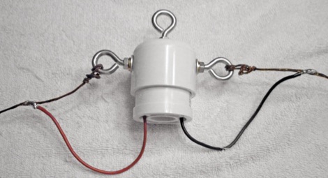 This is another alternative home-brew center connector for a dipole. The parts used are common PVC accesories found at the home supply store.
 -
 A 17 3/4-inch radiating element and 18 3/4-inch ground plane radials form the basis of this quarter-wave ground plane antenna for 2 meters FM. The design, attributed to AA1PG, utilizes a panel-mount SO-239 UHF connector and three lengths of #12 copper wire, with a total material cost estimated at $3.00. Construction involves soldering the elements directly to the SO-239, emphasizing thorough solder flow for robust connections. Recommended feedline includes _RG-8X_ for longer runs, with _RG-58_ acceptable for shorter lengths, cautioning against _RG-174_ for VHF applications due to high loss. The antenna is designed for elevated deployment, such as in trees or on roof gables, to maximize line-of-sight propagation. It aims to improve repeater access compared to typical rubber duck antennas, even with low power output.
 -
 Constructing a mobile HF antenna presents unique challenges, particularly when aiming for multiband operation and robust mechanical stability. This project details N1GY's adaptation of the KM4IE $20 antenna and the _Texas Bugcatcher_ design, focusing on practical build considerations and on-the-road performance. The author shares insights from winding coils on 2-inch PVC forms and integrating a salvaged fiberglass core from an old Hamstick-style antenna to enhance structural integrity, preventing potential failures from stress on PVC joints. N1GY's build includes a custom matching coil and a commercially sourced MFJ loading coil, carefully integrated into the design. The article provides specific tap settings for bands from 75 meters to 15 meters, achieving SWRs as low as **1.2:1** on 40 meters and **1.6:1** on 75 meters. Mechanical testing involved driving at speeds up to 70 MPH on Interstate routes, confirming the antenna's durability and the effectiveness of its PVC brace system. Further modifications address real-world usability, such as simplifying antenna removal for car washes. The ground strap was updated with a Power Pole connector, and the brace attachment to the luggage rack was converted to wing nuts, reducing removal time from 30 minutes to approximately _five minutes_. This iterative design process highlights practical solutions for mobile HF operation.
 -
 Accessories, Antennas and Battery chargers. Radiators, Repeaters, Yagi, Mag, Car, Tetra, Marine, Multiband, Brackets, Mounting accessories, cables and connectors, radiokits, special cables etc. Based in Finland