Search results
Query: component measurement
Links: 36 | Categories: 0
-
 Constructing a 2.4 GHz high-gain _cantenna_ for wireless networks is detailed, providing a practical approach to extending WiFi range. The author, WB8ERJ, shares insights into building these devices, noting their application in amateur radio for projects like Hinternet or HSMM (High-Speed Multimedia) networks. The article outlines the necessary components and steps, emphasizing the DIY aspect for hams interested in digital modes and local area networking. The resource explains how to determine the correct probe placement within the can, a critical dimension for optimal performance at 2.4 GHz. It references specific measurements, such as the 1.25-inch distance from the can's bottom, derived from calculations for the 2.4 GHz band. This precision ensures the antenna functions effectively for its intended purpose of signal amplification. Readers gain actionable knowledge for fabricating a functional antenna from common materials, suitable for experimentation or practical deployment in a ham shack or field environment. The focus remains on the hands-on construction and the measurable results of improved signal strength.
 -
 The project details a DIY SWR/Wattmeter designed around an _Arduino Uno_ shield, providing capabilities to measure RF power from 2 to **200 watts** and Standing Wave Ratio (SWR) for HF amateur radio bands. This construction features a compact design, integrating the measurement circuitry directly onto a custom PCB that interfaces with the Arduino Uno microcontroller. Key components include a directional coupler for sensing forward and reflected power, precision rectifiers, and analog-to-digital conversion for processing RF signals. The Arduino firmware handles calibration, calculations, and displays the results on an integrated LCD, offering real-time feedback on antenna system performance. The design prioritizes simplicity for homebrewers. Performance specifications indicate accurate readings within the **2-200W** power range, suitable for typical QRP to medium-power HF operations. The project provides schematics and a basic overview of the software logic.
 -
 Over 45 years of amateur radio experience inform the homebrew projects detailed on this personal website, with a particular focus on microwave frequencies. The site showcases a 24 GHz transverter and a more recent 47 GHz transverter, demonstrating practical construction techniques for extreme high-frequency operation. These projects often involve custom circuit design and careful component selection to achieve stable performance at millimeter-wave bands. Key projects include a _harmonic converter_ for frequency measurement and a tracking spectrum analyzer, essential tools for microwave experimenters. The site also documents a CW sidetone generator and a TX/RX sequencer, illustrating fundamental building blocks for radio equipment. Details on a digital frequency meter and an S-meter/dBm meter provide insights into test equipment construction. Specific achievements, such as a **24 GHz** tropo QSO with DK3SE in 2021, highlight the operational success of these homebrewed systems. The content reflects a long-standing dedication to self-sufficiency in amateur radio, providing practical examples for those interested in building their own gear.
 -
 Demonstrates the construction of a **homebrew spectrum analyzer** designed by Wes Hayward, W7ZOI, and Terry White, K7TAU, enabling radio amateurs to build a capable test instrument without significant expense. The resource details a _double-conversion superheterodyne_ circuit, employing intermediate frequencies of 110 MHz and 10 MHz, and covers essential blocks such as the time base, logarithmic amplifier, resolution filters, and local oscillators. It highlights the use of hybrid and monolithic ICs, including mixers, amplifiers, and VCOs, to simplify construction while maintaining performance. The design supports useful measurements in the 50 kHz to 70 MHz range, with methods outlined for extending capabilities into VHF and UHF. The authors emphasize that this analyzer, while simple to build, is intended for serious measurements, requiring careful control of signal levels to avoid spurious responses. It uses an oscilloscope for display, with specific instructions for calibration and adjustment of various stages, including the log amplifier and IF gain. The guide provides detailed schematics and component lists for each section, such as the 110 MHz triple-tuned band-pass filter, which achieved **90 dB** image rejection, a significant improvement over double-tuned circuits. Practical advice on alignment and troubleshooting is included, drawing on the authors' extensive experience in RF circuit design.
 -
 Over 75 years of engineering expertise underpins Bird Electronic's offerings in RF power measurement, critical for maintaining peak performance in amateur radio stations and professional communication systems. The company specializes in a range of test equipment, including wattmeters, SWR meters, and antenna analyzers, essential for optimizing antenna systems and ensuring efficient power transfer. Their product line extends to various RF components such as filters, cables, and connectors, all designed to meet stringent technical specifications for reliability and accuracy across diverse frequency bands. Bird Electronic's instruments, like the _Bird 43_ Thruline Wattmeter, are widely recognized for their robust construction and precise measurement capabilities, providing hams with confidence in their station's operational parameters. These tools enable accurate assessment of forward and reflected power, SWR, and modulation characteristics, which are vital for troubleshooting and maximizing radiated power. The company's commitment to innovation ensures that its products remain relevant for modern RF challenges, from HF through microwave applications, supporting both traditional analog and advanced digital modes.
 -
 Constructing a linear focus parabolic antenna for WiFi operation involves precise metalwork, as detailed in this project. The author, AB9IL, shares a build that can be completed in a few hours, emphasizing the hands-on process of shaping and assembling metal components. This design aims to provide enhanced signal range for 2.4 GHz wireless networks, a common challenge in many ham shacks and home setups. The project outlines the practical steps required, from initial measurements to the final assembly, including cutting, bending, and bolting various metal parts. While specific gain figures are not provided, the parabolic design inherently offers significant _directional gain_ compared to omnidirectional antennas, making it suitable for point-to-point links or extending network coverage over distances. The construction process focuses on readily available materials and basic shop tools, aligning with the DIY spirit prevalent in amateur radio. This antenna project is presented as a straightforward build, requiring attention to detail in fabrication to achieve optimal performance.
 -
 Constructing a functional spectrum analyzer for the 0-100 MHz range presents a significant challenge for radio amateurs, often requiring specialized components and careful calibration. This project details a homebrew spectrum analyzer design utilizing common integrated circuits like the _SA605D_ FM receiver IC and _MAR-6_ MMIC amplifiers, aiming for a cost-effective solution. The design incorporates a low-pass filter, RF amplification, a voltage-controlled oscillator (VCO) for downconversion, and multiple IF stages at 150 MHz and 10.7 MHz, with a resolution bandwidth (RBW) of 15 kHz. Critical components such as the _SBL-1_ mixer and varicap diodes are specified, alongside instructions for winding inductors and tuning filters. The analyzer's performance is discussed in terms of input level limitations, specifically the 1dB-compression point and third-order intercept point, to ensure accurate measurements and prevent component damage. The _SA605D_'s logarithmic Received Signal Strength Indicator (RSSI) output serves as the detector, driving the Y-input of an oscilloscope, while a _TL084_ op-amp generates the sweep signal for the X-input. Potential enhancements include adding a step attenuator, improving front-end filtering, and implementing switchable IF filters for variable RBW, allowing for greater versatility in analyzing RF signals.
 -
 Accurately determining an antenna's feedpoint impedance is crucial for optimal performance, especially when experimenting with new designs or making adjustments. While SWR meters provide basic information, a full complex impedance measurement reveals the resistive and reactive components, which are essential for proper matching. Modern antenna analyzers, like the _Palstar ZM30_ or MFJ259B, simplify this task, but measurements taken through a transmission line require careful interpretation due to impedance transformation. This resource details a calibration method to precisely account for the effects of the feedline. It explains how a transmission line can significantly alter the measured impedance, illustrating this phenomenon with a Smith Chart example where an 80m antenna's [22 + j6] Ohms feedpoint impedance transforms to [82 + j45] Ohms after a 10m line. The guide demonstrates using a transmission line calculator applet, such as the one by W9CF, to reverse this transformation. It outlines the process of calibrating a specific length of RG174 coax, showing how an initial 26ft estimate was refined to **25.85ft** to accurately predict a known 22 Ohm load, significantly improving accuracy over uncalibrated results.
 -
 A 4 AMP / 18V regulated power supply schematic, designed by _ON6MU_, provides a detailed circuit diagram for constructing a robust power source. The design focuses on delivering a stable 18-volt output at up to 4 amperes, crucial for powering various amateur radio equipment. This resource presents a clear visual representation of component interconnections, including rectifiers, filter capacitors, and voltage regulation stages, essential for DIY enthusiasts building their shack infrastructure. The schematic's clarity facilitates understanding the power flow and component roles within the circuit. This circuit design offers a practical solution for hams needing a reliable 18V supply, potentially useful for driving specific transceivers, amplifiers, or accessory circuits. While specific performance measurements or comparisons to other designs are not detailed, the schematic itself serves as a foundational blueprint. Builders can adapt or modify the _power supply_ to suit their particular needs, such as integrating overcurrent protection or fine-tuning the output voltage with adjustable regulators. The straightforward presentation makes it accessible for those with basic electronics knowledge to assemble and troubleshoot.
 -
 One point eight MHz to 30 MHz is the operational bandwidth for this 4:1 Ruthroff voltage balun, designed to interface an unbalanced T-Match network with a balanced antenna system. The project details the construction using a _T200-2_ powdered iron toroid core, tightly wrapped in PVC electrical tape for insulation, and wound with 17 double bifilar turns of 1.25mm enamelled copper wire. This outboard balun offers flexibility, allowing hams to trial various baluns based on antenna system and impedance characteristics, rather than integrating it directly into the tuner. The resource includes a schematic of the balun, a wiring diagram showing winding connections, and a table suggesting alternative toroid cores like the T80-2 or T400-2 with corresponding winding counts. Component sourcing is straightforward, listing items such as the _Amidon_ T-200-2 core, SO-239 connector, and a sealed polycarbonate enclosure from Jaycar. Performance evaluation was conducted using an _AIM 4170C_ antenna analyser, demonstrating efficient 1:4 voltage transformation across the specified HF spectrum. Further efficiency tests involved measuring RF power loss at various frequencies, revealing minimal loss—less than 0.7 dB from 3.6 MHz to 30 MHz, and only 2.0 dB at 1.8 MHz. These measurements, performed under ideal 50-ohm conditions, confirm the balun's effectiveness as a low-loss interface for multi-band antenna systems. The page also links to several other balun and unun projects, including 1:1 current and voltage baluns, and 9:1 voltage ununs, providing a broader context for impedance matching solutions.
 -
 SWR (standing wave ratio), is a measurement of how efficiently your antenna system will radiate the power available from your radio. In simple terms, your radio would like to radiate all of its power, but can only do so if the other components cooperate
 -
 The ZS6BKW multi-band antenna, an optimized variant of the classic G5RV, is presented with detailed construction and tuning instructions. This resource outlines the antenna's design principles, which were developed by _Brian Austin (G0GSF)_ using computer programs and Smith charts to achieve optimal dimensions. It provides specific guidance on calculating and adjusting the lengths of the radiators (L1) and the matching ladder line (L2), emphasizing the critical role of velocity factor (VF) in achieving resonance. The article includes a step-by-step procedure for empirically determining the VF of ladder line using an antenna analyzer, ensuring accurate physical lengths for the matching section. It details the tuning process for the radiators, offering practical tips for incremental adjustments to achieve the best SWR curve. The resource presents SWR measurement results obtained with an _AIM-4170C_ analyzer across multiple bands, alongside predicted SWR graphs from an AutoEZ model. It confirms successful contacts on 80, 40, 20, and 17 meters, including a **17-meter DX contact** to Italy. EZNEC and AutoEZ models for the ZS6BKW antenna, covering 80 through 6 meters, are provided for download, allowing further analysis and customization. The document specifies component details, such as the use of Wireman 554 ladder line and #14 AWG THHN copper wire, and discusses the antenna's performance characteristics, noting high SWR on 15 and 30 meters but successful tuning on 6 and 80 meters with an external tuner.
 -
 The resource details the construction of a homebrew 50-watt FET amplifier, based on Don W6JL's _QST Homebrew contest_-winning design from 2009. It functions as an afterburner for QRP transceivers, providing a **12dB** power lift. The amplifier utilizes IRFZ24N FETs and covers the 80, 40, 30, and 20-meter bands, with the 20m LPF extending to 17m. Key technical aspects include an FT37-43 transformer for the input network, a relay-switched 3dB pad for lower bands controlled by an _Arduino Nano_, and an RF-actuated T/R switch. The LPF board integrates four relay-switched filters rated for 50 watts, using capacitors with a minimum 250VDC rating. Performance measurements indicate a power gain ranging from **4.4dB** on 20m to 8.1dB on 80m, with a required drive power of approximately 5 watts. The article also discusses thermal management, current limiting considerations, and component sourcing.
 -
 Demonstrates various practical amateur radio projects and technical discussions through video episodes. One episode details cutting and retuning a _1/4 wave shorted stub_ from 101.7 MHz to 107.5 MHz to safeguard a transmitter's driver stage, alongside insights into advanced _160-meter antenna systems_ like eight-circle arrays and beverage antennas. Another segment covers upgrading firmware on an _ATS-20+_ receiver using AverDudes for improved display and functionality, and a detailed guide on using D-Star DR mode on an _ICOM ID-52A_ for international repeater programming. Additional content includes a deep dive into _OpenHamClock_ as a potential replacement for the HamClock project, updates on _Raspberry Pi 5_ running Trixie OS, and a review of the Choyong LC90 Internet radio with AI integration. The series also features "Ham College" episodes, which meticulously prepare viewers for the Technician Exam by covering topics such as antenna and transmission line measurements, SWR interpretation, and the functions of basic electronic components like rectifiers, relays, and transistors. Practical advice on coaxial cable characteristics, dummy loads, and proper soldering techniques is also provided.
 -
 Millimeterwave/Microwave transmission lines and components, Cryogenic temperature application transmission cables and systems, Permittivity(Dielectric rate) and Permeabillity measurement systems, Antennas, Radar systems
 -
 Accurate frequency measurement is crucial for amateur radio operators, particularly when building or troubleshooting transceivers and test equipment. This resource details the construction of a _PIC microcontroller_-based frequency counter, providing a practical solution for precise frequency display. The design incorporates an LCD readout, offering clear visual feedback of measured frequencies. The counter can operate as a standalone unit, useful for general bench testing, or be integrated directly into a receiver. Its built-in offset functionality allows for seamless integration, enabling the display of the received signal frequency rather than the intermediate frequency. The project focuses on accessible components and construction techniques, making it suitable for homebrew enthusiasts. Key features include a measurement range up to **50 MHz** and a compact form factor.
 -
 This graphics-intensive program reveals the load on the output of a matching-network, based on measurements of the components in that network. Adjust the network (tuner) for a flat input, measure or look up the network component values and you will immmediately see the R and jX values of the load on the network, presented as both a schematic with the component values and as a Smith Chart normalized to the specified system impedance.
 -
 Announces the retirement of Brand Electronics, a manufacturer specializing in **power meters** and various ham radio accessories, effective 2025. The company has served the amateur radio community for over 35 years, providing equipment for station setup and operation. The product line historically included accessories compatible with major transceivers from Icom, Yaesu, and Kenwood, alongside components and technical references for homebrew projects. Their offerings supported accurate RF power measurement, crucial for optimizing antenna systems and ensuring legal limit compliance. This notice serves as a final update regarding the company's operational status, marking the cessation of manufacturing and sales activities. The site provides no further details on product support or inventory liquidation.
 -
 Demonstrates the complete design and development process for a **Low Noise Microwave Amplifier** (LNA), beginning with conceptual design and progressing through prototyping. The tutorial series covers the initial stages of a single-ended first gain stage, focusing on critical parameters such as noise figure, gain, and stability. It systematically details the theoretical underpinnings and practical considerations for achieving optimal performance in microwave frequency applications. This resource provides a structured approach to LNA construction, enabling radio amateurs and RF engineers to understand the iterative steps involved in realizing high-performance receive-side amplification. It offers insights into component selection, impedance matching networks, and the measurement techniques required to validate design specifications, particularly for **microwave** band operation where noise performance is paramount.
 -
 Constructing a dip oscillator provides radio amateurs with a fundamental piece of test equipment for resonant circuit analysis. This particular design, adapted by VK3YE from a concept by _Drew Diamond VK3XU_, details a practical build using readily available components. The unit incorporates four plug-in coils, covering a frequency range from **2.6 MHz to 55 MHz**, mounted on 5-pin DIN plugs for versatility. A salvaged two-gang air dielectric variable capacitor, fitted with a vernier reduction drive, serves as the tuning mechanism, with the smaller gang optimizing bandspread at higher frequencies. In practical application, the dip oscillator is used by setting the meter needle to approximately two-thirds scale. When the instrument's coil is brought near a tuned circuit under test, a noticeable dip in the meter reading indicates resonance. This allows for precise measurement of resonant frequencies in antennas, filters, and other RF circuitry, proving invaluable for homebrewing and troubleshooting. The design emphasizes short wire runs for stable operation, particularly at the higher end of its operational range.
 -
 1500 watts PEP SSB is the power handling capability of the MFJ-989C HF Antenna Tuner, a popular choice among amateur radio operators. Users have shared a wide range of experiences, with some praising its durability and performance over decades of use, while others criticize its build quality and accuracy. The tuner features a built-in dummy load, SWR-wattmeter, and a balun for balanced line feeders, making it versatile for various antenna setups. However, discrepancies in RF power readings and SWR measurements have been noted, with some users finding the dual scale meter to be off by about 20% compared to a Bird wattmeter. Long-term users report that the MFJ-989C performs well with proper antenna setups, but caution against tuning at high power without initial adjustments at lower power levels. Some have experienced issues such as arcing when exceeding 400 watts, while others have had no problems even at higher power levels. The roller inductor and capacitors are functional, though some users have had to perform maintenance like tightening screws or cleaning components to ensure reliable operation. Despite mixed reviews, the MFJ-989C remains in production, suggesting continued demand. It's a tuner that requires careful handling and possibly some DIY fixes to achieve optimal performance.
 -
 Constructing a high-performance RF spectrum analyzer up to 1000 MHz requires careful attention to component selection, shielding, and circuit isolation. This resource details a project that improves upon the _Spectrum Analyzer for the Radio Amateur_ design by Wes Hayward (W7ZOI) and Terry White (K7TAU), incorporating ideas from Scotty Sprowls' project, particularly his 1013.3 MHz IF bandpass cavity filter. The analyzer utilizes a Mini-Circuits SRA-11 mixer with a sweeping local oscillator from 1013 to 2013 MHz, feeding into a 4-pole copper pipe cavity filter. The design employs a second SRA-11 mixer with a fixed 1024 MHz LO to produce a 10.7 MHz final IF. This signal then passes through narrowband resolution filters and is processed by Analog Devices AD603 and AD8307 ICs for IF amplification and logarithmic detection, driving an oscilloscope in X/Y mode. The project emphasizes modular construction, using salvaged components and double-sided FR4 material for PCBs, with critical notes on minimizing spurious images through effective shielding and proper voltage regulation for each module. Key components include a Z-Communications V585ME48 VCO for the first LO and a Z-Comm V583ME01 VCO controlled by a Motorola MC145151 PLL for the second LO. An optional Hittite HMC307 step attenuator and K&L 5L121-1000/T5000-O/O low-pass filter manage RF input. Tuning procedures for the 10.7 MHz IF resolution filter are also detailed, showing before-and-after spectrum views.
 -
 The original SurplusEQ.com domain, once a hub for amateur radio operators and electronics enthusiasts seeking test equipment, meters, and various high-tech components, has been repurposed. Historically, such platforms facilitated the acquisition of essential gear for shack setups, antenna analysis, and general electronics work, often providing cost-effective alternatives to new retail purchases. The site's previous focus on "test equipment, meters, testers" directly supported the technical aspects of the hobby, from RF measurements to circuit diagnostics. Currently, the domain points to a gambling platform named "SEMUTWIN," offering online slot games, live casino options, and other digital wagering activities. This shift represents a complete departure from its former identity as a resource for surplus electronics and amateur radio-related equipment. The content now features game titles like "Sweet Bonanza Super Scatter" and "Gates of Olympus Super Scatter," alongside promotional offers for online gaming.
 -
 Constructing a basic multimeter involves integrating a 0-1mA meter movement with various shunts and multipliers, selected via a switch, to create a versatile instrument capable of measuring DC volts, current, and resistance. The design outlines two main units: a primary unit handling six DC current ranges up to 1 amp and eight DC voltage ranges up to 1000 volts, alongside an internal battery for an ohms range up to 200,000 ohms. This approach allows for a practical, hands-on understanding of meter operation. An add-on unit further extends the multimeter's capabilities, incorporating a meter rectifier and switched series resistors to provide four AC voltage ranges up to 100 volts. Additional shunt and series resistors, designated Ra and Rb, are included to expand the instrument's range to 10A and 5kV, demonstrating how modular design can enhance functionality. When this add-on is in use, the main instrument is set to measure 1mA FSD, connecting via specific lugs. Component selection emphasizes precision, with 1% tolerance high stability resistors for series elements and Eureka resistance wire for shunts. The design specifies values calculated for a meter with 60 ohms internal resistance, noting that these would require modification for different meter characteristics. Experimental adjustment of shunt values is recommended to ensure accurate readings against a calibrated reference meter, reinforcing practical calibration techniques.
 -
 Operating a modern amateur radio station, particularly for advanced digital modes or microwave experiments, often requires precise test and measurement equipment. This resource from NI (National Instruments), now part of Emerson, showcases a wide array of hardware and software solutions designed for demanding test objectives. Their portfolio includes modular instruments and configurable software interfaces, such as _LabVIEW_ and _TestStand_, which integrate AI assistance via _NI Nigel™ AI_ for code completion and sequence building. For those involved in RF and microwave work, the offerings extend to vector signal transceivers, RF signal generators, software-defined radios, and spectrum analyzers. These tools are crucial for characterizing antenna performance, optimizing transceiver circuits, or developing custom radio systems. The company emphasizes its 50 years of innovation, with 40 years dedicated to _LabVIEW_, highlighting a long-standing commitment to engineering solutions. The site also details products for data acquisition, electronic test, and wireless design, covering components like CompactDAQ modules for precise sensor measurements and various communication bus interfaces. Their events and perspectives sections offer insights into topics such as 5G technology and strategies for breaking out of testing silos, providing a broader context for their measurement solutions.
 -
 A 0-30 MHz step attenuator, constructed from switchable Pi attenuation pads, provides a practical tool for evaluating receiver sensitivity and calibrating S-meters. The design utilizes readily available 5% tolerance resistors, with values derived from paralleled components to achieve specific attenuation steps. A schematic (Fig 1) illustrates the circuit, including PCB pad shielding, while a table details required and actual resistor values, along with percentage differences. Measurements of voltage input versus output at various frequencies are used to calculate dB attenuation, presented in a graph (Fig 4). The resource includes formulas for determining output voltage from a known input and a comprehensive 0-40 dB voltage multiplier table, which is crucial for precise signal level management. The project also references external attenuator calculators and equations for further study. Photos (1-3) provide visual guidance for the assembled unit, showing bottom, top, and front views. The project emphasizes the use of **Pi attenuation pads** and **receiver sensitivity** evaluation, offering a hands-on approach to RF signal management.
 -
 Demonstrates MegaPhase's extensive product line of RF and microwave coaxial cable assemblies and components, engineered for demanding applications up to 110 GHz. Key offerings include _Test & Measurement Cables_ with superior phase and amplitude stability, _RF & Microwave Cables_ utilizing _GrooveTube®_ technology for high power systems, and a range of RF components like directional couplers and power dividers. The site details specific cable types such as _Alumibend™_ for space-qualified, ultra-light applications through 90 GHz, and armored cables designed for rigorous environments up to 50 GHz, emphasizing their robust mechanical strength and measurement repeatability. The resource highlights applications across diverse sectors, including space programs like the _Hayabusa_ mission, global security (C5ISR), military airborne systems (MIL-T-81490), telecom, and automated testing. It also provides technical insights through "How To" guides on measuring amplitude/phase stability vs. flexure and proper connector cleaning. The company's commitment to quality is underscored by its rigorous testing protocols and a strong warranty, ensuring reliable operation in critical systems.
 -
 Presents Wayne Kerr Electronics, a manufacturer specializing in precision component measurement products. The company offers a range of LCR meters, impedance analyzers, and transformer test systems designed for various applications in electronics manufacturing and research. Specific product lines include the 3260B Precision Magnetics Analyzer, which measures inductance, capacitance, and resistance with high accuracy, and the 6500B series of LCR meters, capable of testing components across a broad frequency range up to 120 MHz. The 3255B and 3265B series provide solutions for transformer and inductor testing, including turns ratio, leakage inductance, and inter-winding capacitance measurements. These instruments are utilized in quality control, component characterization, and production line testing, ensuring performance and reliability in electronic circuits. Wayne Kerr's offerings support engineers and technicians in verifying component specifications.
 -
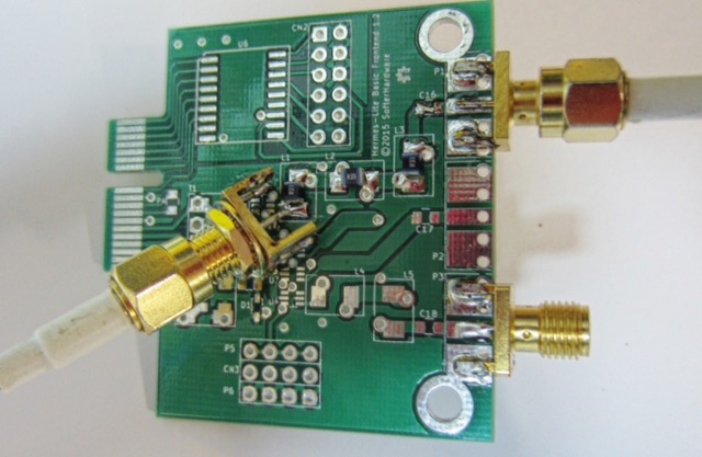 The author has build the Hermes-Lite SDR v1 and v2 versions describing with a very accurated text and picture the process. Additionally has documented measurements for each component
 -
 A 10-meter half-wave vertical antenna, designed by Thomas 4L/G8BAG, offers a practical solution for hams with limited space and materials. This "flower pot" design utilizes common hardware store items such as 60mm plastic drain pipes and 75 Ohm coax cable, demonstrating that effective HF operation doesn't require specialized components. The author details the coax preparation, including stripping the outer sleeve and braid at specific measurements like **2510 mm** and 2450 mm, and integrating it into the pipe structure. The construction emphasizes simplicity and low cost, providing an accessible path to getting on the air on the 10m band, especially when a horizontal beam is not feasible. The article notes an SWR of _1.5:1_ with 75 Ohm coax, managed by an MFJ 258 for impedance matching. This temporary solution proved robust, withstanding various weather conditions and achieving contacts across continents, including W, VK, BG, G, JA, and VR2, using 100W SSB from Georgia.
 -
 An **Arduino LC Meter** provides an accessible solution for precisely measuring inductance and capacitance values, crucial for RF circuit design, filter tuning, and troubleshooting in amateur radio applications. This project details the construction of a low-cost, accurate instrument using readily available components, making it an attractive alternative to commercial units for hams and electronics enthusiasts. The build process involves assembling a resonant circuit, integrating an Arduino microcontroller for frequency measurement, and displaying results on an LCD. Key components include an Arduino Uno, a 16x2 LCD, a 74HC14 Schmitt trigger inverter, and a few passive components. The design leverages the Arduino's processing power to calculate L and C values from resonant frequency shifts. Calibration procedures are outlined to ensure measurement accuracy, which is vital for critical RF work. The project includes schematics, a parts list, and the necessary Arduino code, enabling hams to construct a functional LC meter for their workbench.
 -
 Effective suppression of harmonics and parasitic radiation from HF transmitters is crucial, especially with the increasing sensitivity of VHF/UHF radio channels to interference. This project details a hybrid low-pass filter (LPF) designed to operate across the HF bands up to 51 MHz, making it suitable for 6-meter band operations while providing deep VHF/UHF suppression. The design addresses the challenge of modern interference landscapes, where even microvolt-level signals can disrupt wireless sensors and other simple VHF/UHF receivers. The filter utilizes a single elliptic link, combining high cutoff steepness with robust suppression in the hundreds of megahertz range. A key feature is the use of only two standard capacitor values, simplifying construction and component sourcing. The article provides a detailed schematic, performance characteristics, and _RFSim99_ model file, demonstrating a reflection coefficient S11 below 0.017 (VSWR < 1.03) across 1-51 MHz, ensuring minimal degradation to the antenna system. Construction notes include coil winding specifications and capacitor selection guidance, with recommendations for _FR-4_ assembly. Two capacitor sets are presented, with the first variant recommended for its lower RF current demands, keeping currents below 3 A at 1 kW passing power at 51 MHz. Fine-tuning involves adjusting frameless coils, with considerations for capacitor tolerance and high-frequency capacitance measurement accuracy.
 -
 Twenty 1-watt carbon film resistors are configured in parallel to construct a 50-ohm **dummy load** for amateur radio applications. The design incorporates a heatsink for thermal dissipation and an **SO-239 connector** for RF input, making it suitable for QRP operations. This budget-friendly project details component selection, soldering techniques, and mounting procedures, achieving a continuous power rating of 10 watts and intermittent handling of up to 100 watts across HF and VHF frequency ranges. The resource provides a step-by-step guide for assembly. This construction offers an economical solution for essential shack tasks such as antenna tuning, transmitter testing, and SWR meter calibration without radiating an RF signal. The utilization of readily available components significantly reduces the overall build cost compared to commercial alternatives, providing radio amateurs with a functional and reliable test accessory. While specific VSWR measurements are not provided, the design prioritizes practical utility for low-power transceiver diagnostics and general RF experimentation.
 -
 Demonstrates the design and modeling of a **160m** vertical antenna, dubbed the "WindoVert," specifically for urban amateur radio operators with limited space. The resource covers the theoretical underpinnings of antenna height and radiation patterns, using EZNEC software to analyze current distribution and 3D radiation patterns for various configurations, including a Marconi-style "T" antenna. It details the integration of existing antenna components, such as a Carolina Windom balun and line isolator, into the new vertical setup, and the practical measurement of feedpoint impedance using an antenna analyzer. The article further explores the challenges of achieving low-angle radiation on Top Band, emphasizing the critical role of radial systems and mitigating ground loss. Author VE1ZAC presents EZNEC models illustrating the impact of lumped components and discusses the practical considerations of resonant frequency adjustment and impedance matching for **QRP** operation. The text details the calculation of required loading coil inductance and capacitance, and shares field results, including successful DX contacts on 160m and unexpected excellent performance on 30m.
 -
 Demonstrates the construction of an active loop converter specifically designed for the Low Frequency (LF) bands, addressing common localized noise interference in LF reception. The design integrates a sharply tuned circuit and a tuned loop antenna, utilizing the loop as the sole tuned inductive element. By applying positive feedback, the converter significantly increases the loop's effective Q, achieving factors between 1000 and 2000, which sharpens tuning and reduces noise. The circuit employs an _NE602_ mixer stage, feeding its output to an HF receiver, with a crystal-locked local oscillator at 4 MHz. A 20-turn, 0.8-meter square loop antenna with 500 uH inductance is detailed, connected via 2 meters of figure 8 flex cable. The converter offers three selectable frequency bands: 195-490 kHz, 150-220 kHz (including the New Zealand amateur band), and 128-160 kHz (covering the European amateur band). Performance measurements indicate an effective 3dB bandwidth of approximately 100 to 200 hertz at 200 kHz. The article provides insights into component selection, including an _LF353_ op-amp and a trifilar wound transformer on a ferrite core. Sensitivity figures are presented, showing 7.5 uV of converted output per 1 uV/meter signal strength into a 50-ohm load, or 37.5 uV into an _FRG7_ receiver, highlighting its capability to extract weak signals from noise.
 -
 This online construction guide details the assembly of a signal generator specifically for the **13cm band** (2.4 GHz). The curriculum focuses on the integration of a Voltage Controlled Oscillator (VCO), specifically the ROS-2400, to produce a stable RF signal. The resource outlines the necessary components for frequency generation and output, including the use of a Mini-Circuits MMIC amplifier for signal conditioning. The construction protocol involves configuring the ROS-2400 VCO to operate within the 2.3 GHz to 2.45 GHz range, ensuring frequency coverage for amateur radio _microwave experimentation_. The guide specifies the output power level, approximately 70mW, directly from the MMIC stage, indicating its application as a low-power instrumentation source rather than a transmit-capable device. This project provides a practical example of constructing a dedicated test instrument for microwave frequency measurements and system alignment on the **13cm band**. DXZone Focus: Construction Guide | 13cm Signal Generator | VCO Integration | Microwave Experimentation