Search results
Query: high voltage
Links: 50 | Categories: 1
Categories
-
 Demonstrates the construction of **magnetic loop antennas**, detailing both multi-turn and single-turn designs. It covers a 30-inch diameter multi-turn loop for 80 meters, based on a February 1996 QST article, and an octagon single-turn loop made from 15mm copper tube with a 4.8-meter circumference, operating from 7 MHz to 14 MHz. The document also presents a smaller 800mm diameter loop for 14 MHz to 28 MHz, emphasizing the importance of high-voltage tuning capacitors. Covers the design and construction of custom **butterfly capacitors** and piston capacitors, including a split stator capacitor with 140 pF capacitance and a 6000 Volt rating, and a butterfly capacitor with 5-65 pF and 7200 Volt rating. It explains why butterfly capacitors are preferred over split stator types for high power applications due to lower losses and direct series connection of rotors, reducing resistive losses from wiper contacts. Material recommendations include clear PVC for plates and brass or stainless steel for non-magnetic hardware. Addresses practical considerations such as feeding the loop with a shielded 1/5 Faraday loop made from RG213 or RG8 coax, achieving VSWR 1.1 across bands, and optimizing its placement 180° from the capacitor. It also discusses mechanical joint resistance, dissimilar metal oxidation prevention using Vaseline, and a simple method for determining radiation angle with a TL-light tube. The guide includes diagrams for rotor, stator, and end plate construction.
 -
 For radio amateurs considering homebrew antenna projects, this resource details several designs from WE6W, an experienced operator. It covers the construction and characteristics of a _160 Meter QRP Loop Antenna_ optimized for high voltage, along with standard and folded variations of the double bazooka antenna. The site also presents a unique Field Day antenna design and instructions for building a Sterba Curtain, a directional array known for its gain. Each design includes practical insights from the author's building experience. The author provides comparative data, such as the performance of a standard bazooka against a traditional dipole, offering real-world context for antenna selection. The Sterba Curtain section includes notes on its beamwidth and gain, crucial parameters for directional operation. These designs are suitable for hams looking to experiment with cost-effective, high-performance antennas for various bands and operating scenarios, from QRP on 160m to directional DXing with a Sterba Curtain, which can offer significant forward gain, often exceeding **10 dB**.
 -
 Optimizing the impedance transformation and common-mode current suppression in antenna systems often involves selecting an appropriate balun. This project presents a **hybrid balun** design, combining characteristics of both voltage and current baluns to achieve superior performance, particularly when used with an antenna tuner. The design addresses issues like **common-mode current** on the feedline, which can distort the antenna's radiation pattern and introduce RFI in the shack. The construction details include winding techniques for the toroid core, component selection, and practical considerations for integration into an existing antenna system. Performance comparisons are drawn against conventional balun types, highlighting the hybrid balun's effectiveness across the HF bands. The resource provides insights into the current distribution and impedance matching properties, crucial for efficient power transfer and reduced SWR.
 -
 The _Astron RS35m Power Supply Schematic_ provides a detailed circuit diagram for this popular linear power supply, focusing on the rectifier and pass transistor stages. It presents the AC input and DC output sections, illustrating the component layout and interconnections critical for understanding its operation. The schematic is enhanced with specific annotations derived from the December 2005 QST "Hands-On Radio, Experiment #35 Power Supply Analysis." These notes offer insights into the circuit's functionality and potential analysis points, making the diagram more instructive than a bare schematic. The resource serves as a practical reference for hams interested in the internal workings or maintenance of the _Astron RS35m_ unit. This document specifically highlights the key components responsible for voltage regulation and current delivery.
 -
 A 144 MHz kilowatt amplifier project details the construction and performance of a high-power VHF linear using the GU74b tetrode. This Russian tube, equivalent to the Svetlana 4CX800, is noted for its conservative datasheet ratings, performing closer to 800-1000W anode dissipation in practical applications. The design prioritizes compactness and achieves 1.2 kW output with only 20W of drive power, demonstrating a 70% efficiency at 2.5 kV plate voltage. The amplifier has been successfully deployed in demanding _EME_ (Earth-Moon-Earth) operations since June 1994. Challenges encountered during development included achieving stability with a grid-1 input configuration. The author, _CT1DMK_, opted not to publish the full design due to its complexity, suggesting it might be difficult for less experienced builders to replicate successfully. However, he invites direct contact for those with specific interest in the design. Future plans include a "144MHz GS35b compact amplifier" project, promising another kilowatt-plus design. This resource offers insights into high-power VHF amplifier construction and the practical application of specific power tubes.
 -
 Presents a crystal-controlled CW transmitter design for the 40-meter band, delivering 5 to 7.5 watts output power. The circuit innovatively employs an _IRF510_ power MOSFET in the final amplifier stage, diverging from conventional bipolar transistors. This design offers high gain, nearly 90% efficiency, and robust resistance to high SWR, allowing 30-second key-down operation into an open circuit without damage. A critical aspect is the precise adjustment of the MOSFET gate bias via a 10K trimmer pot, _R10_, to maintain quiescent current between 5 and 10 mA, preventing thermal runaway inherent to bipolar devices. The prototype was constructed on a _Radio Shack universal board_ and achieved immediate operational success. The design requires a 15-volt Zener diode to protect the MOSFET gate from overvoltage. Component sourcing information is provided, including specific crystal frequencies (7.040 MHz or 7.122 MHz) available from _Dan’s Small Parts & Kits_ or Doug Hendricks. The fixed frequency can be slightly adjusted with a trimmer capacitor. A complete bill of materials, including resistor values, capacitor types, toroid specifications, and transistor part numbers, is detailed, alongside a clear schematic diagram.
 -
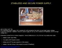 Dchematics and photos of a secure power supply (short-cut, Rf feedback, high voltage etc.) by iz7ath
 -
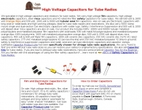 "Sells high voltage film and electrolytic capacitors for antique tube radios. Carries 630 volt metal-film, metallized and mylar film capacitors as well as electrolytics. Also has ""capacitor"" tips for antique radio restorations."
 -
 Unified Microsystems presents a range of amateur radio products, notably the **XT-4 MK2 CW Memory Keyer**, a battery-powered iambic keyer designed for portable operations like Field Day, POTA, SOTA, and DXpeditions. It features four non-volatile memories, each storing approximately 240 Morse characters, and operates at speeds from 8-45 WPM. The XT-4 MK2 also includes an auto power save function and paddle reverse, making it adaptable for multi-operator setups. Beyond the XT-4 MK2, the site details the **W9XT Contest Card**, a PC plug-in board offering DVK and CW interface capabilities, allowing operators to record and playback CQs and contest exchanges. Other offerings include the BevFlex-4X RX Antenna System, RAS-4 RX Antenna Switch, VK-64 Voice CW Keyer, and various USB interfaces. Additional products cover electronic development, such as the ATS-1 Terminal Shield for Arduino™ and VR-X Power Supply Voltage Regulators, demonstrating a broader scope beyond just operating accessories. The XT-4Beacon MK2 / CW IDer is also highlighted for beacon projects, capable of storing messages up to 5 minutes at 25 WPM.
 -
 Presents the design and construction of the OK2FJ Bigatas, a portable, automatically tuned vertical antenna covering 80 through 10 meters. It details two distinct control systems: one utilizing BCD band data from Yaesu FT-857/897 transceivers, and another employing voltage level sensing for the Yaesu FT-817. The resource provides specific instructions for building the antenna's radiating element, loading coil with switchable taps, and the control circuitry, emphasizing the use of readily available components. The article outlines the physical construction of the antenna, including the use of duralumin tubes for the radiator and a PVC tube for the coil form. It specifies coil winding details, tap points, and the integration of radial wires for ground plane operation. The control electronics section provides schematics and component lists for both the BCD decoder (using a 74LS42 IC) and the voltage comparator (using an _LM3914_ bargraph driver), enabling rapid, automatic band switching without the minute-long tuning delays common in other systems. Crucially, the antenna achieves rapid band changes, with typical SWR values centered on common operating segments, such as **3.7 MHz** for 80m SSB. It also discusses modifications for CW operation on 80m and the trade-offs between antenna efficiency and full-range automatic tuning on higher HF bands, where manual adjustment of radiator length is suggested for optimal performance on 15m, 12m, and 10m. The resource includes construction photos and a discussion of cable requirements for reliable operation.
 -
 High Voltage Supply for GS 35B Amplifier
 -
 Engineering Solutions for Unique Problems. Manufacturer of high Voltage, high Current, high Power Power Supply
 -
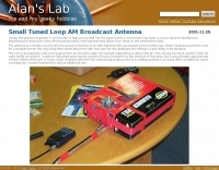 Alan yates vk2zay's ham radio website, homebrew construction, general electronics, high voltage experiments, amateur rocketry, and general geek stuff
 -
 The Collins TRC-75 autotune linear amplifier, owned by JF2SVU, is presented with a focus on its internal modifications. This QRO amplifier utilizes three 4CX250 tubes in parallel for its final stage, delivering 1 KW output power. Notably, the amplifier achieves full power with only 100 mW of RF input, a characteristic often associated with Collins designs. The original 400 Hz power supply has been converted for easier shack integration, and the entire RF and power supply sections have been rehoused into a compact, clean enclosure. The control unit, positioned above the amplifier, features three meters for individual vacuum tube IP monitoring and a multi-meter on the right. A dedicated 7 MHz receiver, recently completed, is also part of this integrated system. The autotune functionality means the main amplifier unit only requires connections for power, control, and coaxial cables, simplifying its operation. Key components like the 4CX250 tubes and NF capacitors are visible, along with the gearing mechanism for the final tank circuit. A timer and relay system manages high-voltage delay and cooling fan off-delay, although the cooling fan's airflow is noted as somewhat insufficient. A central volume control, which experienced a contact issue, is also highlighted.
 -
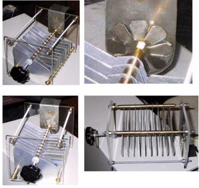 Building a high voltage (5KV), variable plate capacitor (17 to 220pF)
 -
 Radio frequency systems require robust protection against transient voltage events, which can severely damage sensitive equipment. This resource details a range of **RF surge protection** devices, including models with DC Pass, DC Block, Bias T, and Ultra Low PIM characteristics, designed to safeguard critical infrastructure. It also presents various RF filtering solutions and interconnect components, emphasizing their role in maintaining signal integrity and operational continuity across diverse applications. The site provides information on products engineered for both RF and data line protection, highlighting their utility in preventing downtime and equipment loss. Specific product categories encompass coaxial protectors, grounding items, and fiber optic solutions, indicating a broad scope of application from amateur radio installations to industrial and telecommunications networks. Furthermore, the resource mentions the availability of NOM-certified products and offers same-day shipping for many items, underscoring a commitment to rapid deployment and compliance with industry standards.
 -
 Demonstrates how to construct an automatic band decoder, moving beyond manual selector switches for antenna and filter control. It addresses the challenge of varying band data outputs from different transceivers: Icom rigs provide voltage values, Yaesu rigs use Binary Coded Decimal (BCD), and Kenwood rigs lack direct band data output. The resource highlights a clever solution utilizing logging software like _CT (K1EA)_ and _DX4WIN_ to emulate Yaesu's BCD output via a PC's printer port, making the decoder compatible with any rig. The author details experiences building decoders based on designs by Bob _K6XX_ and Guy _ON4AOI_, noting K6XX's simple TTL chip design and ON4AOI's more comprehensive, opto-isolated unit capable of controlling ten outputs and bandpass filters like the _Dunestar_. It also references a _W9XT_ board design, which Steve Wilson, G3VMW, modified with BD140 transistors for source drivers, emphasizing safety. The author successfully cased an ON4AOI-based decoder in an old modem case, connecting it to an FT1000MP or a PC printer port to drive remote relays and a Dunestar Band Pass Filter.
 -
 Examines the Icom IC-2100H 2-meter mobile transceiver, detailing its operational characteristics and user experience. The review highlights the clear, easy-to-read display with internal labels, the button-filled microphone's functionality, and the rig's physical construction, including its weighty heat-sink and lack of a cooling fan. It also discusses memory programming, the unique amber-to-green backlight color options, and the radio's performance against _intermodulation_ in urban environments, noting it performs "pretty darn good" compared to other rigs. The analysis delves into a significant low-voltage cutoff problem, where the microphone ceases to function below approximately **12.6 VDC**, rendering the radio receive-only or causing it to stick in transmit. The author describes testing the voltage cutoff, observing it fluctuate from _12.38 VDC_ to 12.69 VDC. An update from Icom involved a "factory update" to the CPU's control code, which is strongly recommended for early-serial number units to prevent operational failure in low-power emergency scenarios.
 -
 1500 watts PEP output from a Kenwood TL-922 amplifier requires careful attention to parasitic suppression and component selection to ensure stability and longevity. This resource critically examines common modifications, often based on anecdotal evidence rather than sound engineering principles, that can degrade performance or introduce new issues. It highlights how replacing aged components often gets misattributed to the efficacy of unnecessary modifications, leading to widespread misinformation within the amateur radio community regarding amplifier stability. The article details specific, effective modifications for the TL-922, such as shortening anode-to-chassis and anode-to-grid paths to improve VHF stability and efficiency. It addresses issues like incorrect capacitor types in the tank circuit, inadequate grid grounding, and poor RF sheet metal design, providing practical solutions like adding direct ground connections for the plate tune variable capacitor. The author also discusses proper parasitic suppressor design, emphasizing the importance of lead length and component selection for optimal performance and harmonic suppression, contrasting these with less effective or detrimental 'magical suppression kits'.
 -
 Protecting amateur radio equipment from transient overvoltages requires robust lightning and surge protection, which is the focus of Electronic Specialty Products. The company provides various devices, including coaxial lightning arrestors for antenna feedlines and surge protectors for AC power lines and data circuits. These devices are engineered to divert high-energy surges, such as those caused by direct or indirect lightning strikes, away from sensitive transceivers, amplifiers, and computer components, thereby preventing catastrophic damage. Key products include the _Coaxial Lightning Protector_ series, designed for various impedance levels and frequency ranges up to 3 GHz, and the _AC Line Surge Protector_ for shack power distribution. Effective deployment of these protection devices can significantly reduce the risk of equipment failure and ensure operational continuity during severe weather. For instance, a properly installed coaxial arrestor can handle peak currents of **20 kA**, while AC line protectors offer clamping voltages typically below 400V. Comparing different models reveals varying levels of insertion loss and return loss, with some coaxial units exhibiting less than 0.1 dB loss at 500 MHz, making them suitable for high-performance HF and VHF/UHF operations. Integrating these components into a comprehensive grounding system is crucial for achieving maximum protection against both common-mode and differential-mode surges.
 -
 Magnetic Loop Antennas for The Radio Operator with Limited Space, a two part series of articles on how to construct a magnetic loop antenna, including directions on selecting high voltage tuning capacitor
 -
 A frame antenna for the 80 meters band, built to be folded and to be easy to be mounted and dismounted. This antenna is suitable for indoor and QRP use, bandwidth is just 10kHz and should be observed a proper distance while transmitting due to high voltage.
 -
 An High voltage power supply design by F1FRV
 -
 Operating a ham station often involves encountering radio frequency interference (RFI), RF feedback, or RF burns, which are frequently misattributed to poor equipment grounding. This resource meticulously dissects these assumptions, asserting that RF grounds on the operating desk often merely mask more significant system flaws. It identifies five primary causes for RF problems, including antenna system design flaws, proximity of the antenna to the operating position, DC power supply ground loops, equipment design defects, and poorly installed connectors or defective cables. The content emphasizes that issues like "hot cabinets" or changes in SWR when connecting a ground indicate substantial RF flowing over wiring or cabinets, a phenomenon known as common-mode current. The article provides detailed explanations of common-mode current generation, particularly from single-wire fed antennas like longwires, random wires, and OCF dipoles, which inherently present high levels of RF in the shack. It also illustrates how vertical antennas, lacking a perfect ground system, can excite feed lines with significant common-mode current. Through simulations, the author demonstrates how a dipole without a proper _balun_ can cause RF problems at the operating desk, showing current patterns and voltage distributions on feed line shields. The discussion extends to the proper application of _RF isolators_ and _ferrite beads_, clarifying their role in modifying common-mode impedance on cable shields and cautioning against their use as a band-aid for fundamental system defects. The resource advocates for correcting the actual source of RF problems, such as antenna system issues or poor connector mounting, rather than relying on internal shack grounding or isolators. It highlights that properly functioning two-conductor feed lines, like coaxial or open-wire lines, should result in minimal RF levels at the operating position, even without a desk RF ground. The author shares personal experience, noting that his stations since the late 1970s have operated without RF grounds at the desks, relying instead on proper antenna system design and feed line integrity.
 -
 Vapex Tech offers over **150 different battery products** tailored for diverse applications, including specific models for Icom, Kenwood, and Yaesu handheld transceivers. The product catalog details specifications for NiMH, LiPo, and LiFePO4 chemistries, providing crucial data on voltage, capacity, and discharge rates. Customers can browse by application, such as _Airsoft Batteries_ or _Model Control Batteries_, or directly by consumer battery types like AA and AAA cells. The resource presents a structured e-commerce platform where users can filter products by category, view detailed item descriptions, and proceed with online purchases. Each product listing includes high-resolution images and key technical parameters, enabling informed selection for specific radio equipment. Operational hours are clearly stated as 9am-5pm Mon-Fri and 9am-12pm Sat, with contact information including a sales email and phone number for direct inquiries. The site also features a "Latest News" section, indicating ongoing updates regarding product availability or company information.
 -
 A synthesized 2.3 GHz Amateur Television (ATV) transmitter design, conceived by Ian G6TVJ, is presented, targeting broadcast-quality video performance on the 13cm band and extending up to 2.6 GHz. The core of the design utilizes a commercial Z-comm Voltage Controlled Oscillator (VCO) that tunes from 2.2-2.7 GHz, providing a +10 dBm output and simplifying RF alignment. This VCO's stability, originally intended for narrowband applications, readily accepts high-frequency video modulation, contributing to the transmitter's robust performance. The exciter stage, incorporating a Mini Circuits VNA 25 MMIC amplifier, boosts the signal to +16dBm, while a Plessey SP4982 prescaler divides the output frequency for the synthesizer. The synthesizer employs a Motorola MC145151 CMOS parallel IC, favored over the common Plessey SP5060 for its superior video modulation characteristics and ease of programming without microprocessors. This choice addresses issues like LF tilt and distorted field syncs often seen with SP5060 designs, particularly when operating through repeaters or over long distances. The MC145151 divides the signal further, enabling precise frequency stepping, with programming handled by EPROMs for channel selection and LED display. The loop filter network, critical for video integrity, was developed through experimentation to prevent the PLL from reacting to video modulation, ensuring a clean transmitted picture. The transmitter incorporates a Down East Microwave commercial power amplifier module, delivering approximately 1.6W output, driven by the exciter through a 3dB attenuator. Construction involves surface-mount SHF components on micro-strip lines etched onto double-sided fiberglass board, housed within a tinplate box. The design boasts no AC coupling in the video path, preserving low-frequency response, a common failing in other ATV transmitters. Performance tests with a 50Hz square wave revealed no LF distortion, and a calibrated "Pulse & Bar" signal showed a near 100% HF response, demonstrating its capability for high-quality ATV transmissions.
 -
 K8CU technical topics article about high voltage breakdown tester necessary for testing of any high voltage components like vacuum tubes, high voltage capacitors, vacuum relay
 -
 FMI provides superior solutions in the design and manufacture of frequency control devices including Voltage Controlled Temperature Compensated Crystal Oscillators (VCTCXO), voltage controlled crystal oscillator (VCXO), Temperature Compensated Crystal Oscillators (TCXO), crystal clock oscillators, high temperature oscillators, surface mount and crystal oscillator products, phase locked sources and more.
 -
 The WB5RVZ Genesis Radio G40 build log documents the construction of a 5W QRP 40m SDR transceiver kit, detailing each phase of assembly from power supply to RF filtering. It provides specific component lists, parts placement diagrams, and testing procedures for stages like the local oscillator, Tayloe detector, and RX op-amps. The resource highlights discrepancies between documentation versions and offers practical advice for builders, including a "virtual build" approach to preemptively address potential ambiguities in component identification and placement. It also addresses a specific "VK6IC Fix" for early board revisions, involving trace cuts and jumper wires for improved performance. The build log presents measured voltages and expected current consumption for various stages, such as the 4.9-5.0 Vdc on the 5V rail and under 100mA for RX current. It outlines critical adjustments like image rejection tuning, a common procedure for direct conversion receivers. The resource also includes practical tips for handling components like the 2N3866 transistor and its heatsink, emphasizing pre-assembly. It details the winding of two 1.45 uH toroidal inductors on T50-6 cores with 17 turns of #20 AWG wire, crucial for the RF path.
 -
 Demonstrates the fundamental principles for connecting a personal computer to a ham radio transceiver, specifically for utilizing sound card-based digital mode software like those in the MM Hamsoft suite. It details the basic hardware setup, emphasizing the use of shielded leads and proper audio routing from the radio's output to the sound card's input, and from the sound card's output to the radio's microphone or data input. The resource highlights the critical need for transmit attenuation, suggesting a 100:1 voltage divider to prevent overdriving the transmitter's audio stage, and mentions the optional addition of ferrite beads and decoupling capacitors for RFI mitigation. The guide also points to external resources for more detailed pin-outs and interface schematics, such as a specific QSL.net page, and recommends consulting the help files within MM Hamsoft programs for interfacing specifics. It underscores that while the process is straightforward, understanding the audio level management and proper cabling is key to successful operation. The author, VE5KC, provides practical advice drawn from common issues encountered by operators setting up digital mode stations.
 -
 The N1HFX thermal cooling fan controller project details a practical circuit designed to manage cooling fan operation based on temperature, a common requirement for high-power amateur radio equipment. This build utilizes a **LM34** temperature sensor, providing a linear voltage output directly proportional to Fahrenheit degrees, simplifying the control logic. The circuit's core functionality involves a comparator that activates the fan when a preset temperature threshold is exceeded, ensuring efficient cooling and reducing unnecessary fan noise. This controller is particularly useful for amplifiers, power supplies, or transceivers that generate significant heat during operation. The design incorporates a _TIP120 Darlington transistor_ to drive the fan, capable of handling up to 5 amps, making it suitable for a range of fan sizes and current requirements. Field results indicate stable temperature regulation, preventing thermal runaway in enclosed environments. Construction involves readily available components, making it an accessible project for hams looking to optimize their station's thermal management.
 -
 Constructing a high-performance RF spectrum analyzer up to 1000 MHz requires careful attention to component selection, shielding, and circuit isolation. This resource details a project that improves upon the _Spectrum Analyzer for the Radio Amateur_ design by Wes Hayward (W7ZOI) and Terry White (K7TAU), incorporating ideas from Scotty Sprowls' project, particularly his 1013.3 MHz IF bandpass cavity filter. The analyzer utilizes a Mini-Circuits SRA-11 mixer with a sweeping local oscillator from 1013 to 2013 MHz, feeding into a 4-pole copper pipe cavity filter. The design employs a second SRA-11 mixer with a fixed 1024 MHz LO to produce a 10.7 MHz final IF. This signal then passes through narrowband resolution filters and is processed by Analog Devices AD603 and AD8307 ICs for IF amplification and logarithmic detection, driving an oscilloscope in X/Y mode. The project emphasizes modular construction, using salvaged components and double-sided FR4 material for PCBs, with critical notes on minimizing spurious images through effective shielding and proper voltage regulation for each module. Key components include a Z-Communications V585ME48 VCO for the first LO and a Z-Comm V583ME01 VCO controlled by a Motorola MC145151 PLL for the second LO. An optional Hittite HMC307 step attenuator and K&L 5L121-1000/T5000-O/O low-pass filter manage RF input. Tuning procedures for the 10.7 MHz IF resolution filter are also detailed, showing before-and-after spectrum views.
 -
 Schematic diagram for a high voltage power supply by W4NFR
 -
 Demonstrates the construction of a high-power 6-meter (50 MHz) amplifier, specifically designed for demanding modes like EME, TEP, and multiskip Es. It details the use of a _GU-43B_ tetrode in a grounded-cathode configuration, emphasizing the need for stabilized grid voltage and input capacitance compensation. The resource provides a comprehensive schematic, power supply design, and practical considerations for component sourcing, particularly for high-voltage and high-current sections. The builder achieved an output power of **1250 watts** with an anode current of 0.65 amperes and 3200 volts anode voltage. The article also covers the physical construction within a modified P6-31 enclosure, outlining the internal layout for RF and power supply sections, and includes photos of the completed unit. It highlights critical safety precautions for working with high voltages and reactive currents up to **20 Amperes** in the P-network.
 -
 Constructing a basic multimeter involves integrating a 0-1mA meter movement with various shunts and multipliers, selected via a switch, to create a versatile instrument capable of measuring DC volts, current, and resistance. The design outlines two main units: a primary unit handling six DC current ranges up to 1 amp and eight DC voltage ranges up to 1000 volts, alongside an internal battery for an ohms range up to 200,000 ohms. This approach allows for a practical, hands-on understanding of meter operation. An add-on unit further extends the multimeter's capabilities, incorporating a meter rectifier and switched series resistors to provide four AC voltage ranges up to 100 volts. Additional shunt and series resistors, designated Ra and Rb, are included to expand the instrument's range to 10A and 5kV, demonstrating how modular design can enhance functionality. When this add-on is in use, the main instrument is set to measure 1mA FSD, connecting via specific lugs. Component selection emphasizes precision, with 1% tolerance high stability resistors for series elements and Eureka resistance wire for shunts. The design specifies values calculated for a meter with 60 ohms internal resistance, noting that these would require modification for different meter characteristics. Experimental adjustment of shunt values is recommended to ensure accurate readings against a calibrated reference meter, reinforcing practical calibration techniques.
 -
 The resource, "Conventional Use of Transmission Line," meticulously details the operational principles of transmission lines, emphasizing the Transverse Electromagnetic (TEM) mode of energy transfer. It clarifies that for a line to function purely as a transmission line, all currents must be confined internally, with external fields ideally zero. The discussion differentiates between balanced and unbalanced lines, asserting that while both require equal and opposite currents within the conductors, the key distinction lies in the voltage relationship of each conductor to the surrounding environment. It highlights that a good antenna pattern does not inherently confirm proper feeder balance, and that common-mode currents can lead to RF in the shack and increased noise levels, even without pattern distortion. The article further explains that a transmission line can become a radiating conductor if energy is applied in a non-TEM mode, leading to common-mode issues. It cites classic texts like Jordan and Balmain's "_Electromagnetic Waves and Radiating Systems_" and Kraus's "_Antennas_" to support its definitions of TEM mode operation. The content also explores non-transmission line applications of parallel or concentric conductors, such as _coaxial dipoles_ and _folded dipoles_, which intentionally operate in non-TEM modes for antenna functionality. The author, _W8JI_, stresses that simply measuring equal currents is insufficient to confirm a balanced feeder; phase and voltage balance to ground are equally critical.
 -
 One common semiconductor material, silicon, is far more widely used in electronics than germanium, partly because it can operate at much higher temperatures. Semiconductors are crystalline materials with electrical resistivity values between conductors and insulators, whose conductivity can be altered through _doping_ with impurities like arsenic or phosphorous to create N-type (excess electrons) or P-type (electron vacancies) materials. Semiconductor devices, such as diodes, transistors, and integrated circuits, leverage these properties to control electron flow in circuits. A diode, a two-terminal device with an anode and cathode, primarily permits current flow in one direction, making it useful as a rectifier to convert AC to DC. Specialized diodes include Zener diodes for voltage regulation and Light-Emitting Diodes (LEDs) that produce light when current passes through them. Logic circuits, fundamental to digital electronics, have binary inputs and outputs, performing functions like AND, OR, and NOT gates, and can be constructed from various binary devices including solid-state diodes and transistors. A transistor is an active semiconductor device with at least three terminals (base, emitter, collector), capable of amplifying current. Integrated circuits (ICs), often called chips, are electronic circuits built on a semiconductor substrate, typically silicon. ICs are classified by transistor type (bipolar or MOS) and integration scale: Small-Scale Integration (SSI) with fewer than 10 transistors, Medium-Scale Integration (10-100), Large-Scale Integration (LSI) with 100-1,000, and Very-Large-Scale Integration (VLSI) with more than **1,000** transistors. ICs can be analog, digital, or hybrid, offering virtually limitless functions.
 -
 Offers a range of high-performance RF interconnect solutions, addressing the critical need for reliable signal integrity across diverse radio frequency applications. Their product line includes custom cable assemblies, various **RF connectors** (such as SMA), adapters, and terminators, designed to meet stringent specifications from DC up to 40 GHz. These components are essential for maintaining low insertion loss and excellent VSWR in demanding environments, from test benches to operational communication systems. The company specializes in providing tailored solutions for both commercial and government sectors, emphasizing precision manufacturing in Warner Robins, Georgia. Their offerings are crucial for engineers and operators requiring specific lengths, connector types, and performance characteristics for their radio equipment and test setups. Ensuring robust connections and protection against transient voltage events, their **surge protectors** are integrated into systems to safeguard sensitive electronics from damage, a common concern in outdoor or high-power installations.
 -
 Replacement high voltage metering resistors procedure
 -
 Operating in a Single Operator Two Radios (SO2R) setup, especially with beverage antennas, often exposes the receiving radio's front-end to significant RF energy from the transmitting radio. This resource details a practical, homebrew receiver protection circuit designed to mitigate this risk. The core of the design involves a non-inductive 2W 22 Ohm carbon composition resistor in series with the RX antenna line, followed by two stacks of four fast-switching diodes (e.g., _1N914_) configured in opposite polarizations. This arrangement effectively clamps the incoming voltage to approximately 2.8 V peak-to-peak, safeguarding sensitive receiver input components. The series resistor plays a crucial role by absorbing excess power, preventing the diodes from exceeding their current ratings and potentially failing open, which would leave the receiver unprotected. The author, _N4KG_, measured up to 50 watts of coupled power between 80M slopers on the same tower, highlighting the necessity of such protection. The design is presented as a cost-effective solution to prevent damage to receiver input transformers, with the author noting successful protection of a receiver even after a resistor showed signs of overheating. This simple circuit can be integrated via a transverter plug, offering a robust defense against high RF input.
 -
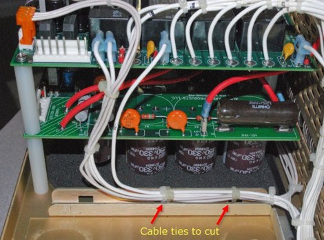
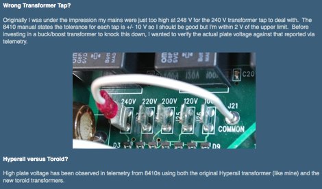 High Plate Voltages Reported via Telemetry on Alpha 8410 power amplifier by AE9K
 -
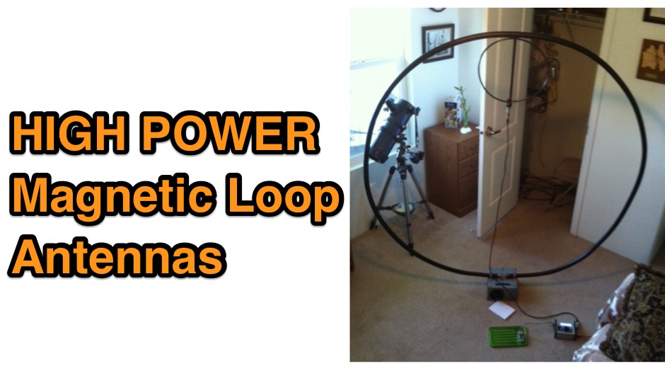
 This tutorial provides detailed instructions for constructing a DIY magnetic loop antenna, ideal for amateur radio operators seeking efficient short wave communication. The design features a remote tuning system utilizing an Arduino and RC servo, making it suitable for indoor use where larger antennas cannot be installed. Magnetic loop antennas are compact and can operate effectively in confined spaces, but they do require careful handling due to the high voltages and currents they generate during operation. Users should possess the necessary technical skills to implement this project safely. The tutorial includes a comprehensive overview of the antenna's theory, specifications, and mechanical design. It outlines the components needed, including a Soviet-made variable capacitor and a digital RC servo for tuning. Safety precautions are emphasized, as the antenna can produce several kilovolts of voltage and high currents. The project is not certified for safety, and users are advised to proceed at their own risk. The tutorial also provides diagrams and explanations of the antenna's operation, making it a valuable resource for both beginners and experienced operators looking to enhance their setup.
 -
 WB8LZR details the construction and initial field results of a multi-band vertical wire antenna, designed to complement his existing horizontal loop for improved DX on 80 meters. The antenna utilizes a 67-foot vertical wire, configured as a quarter-wave radiator on 80m, and employs a 1:1 current balun for RF isolation on 80m, 30m, and 17m. For bands like 40m, 20m, and 10m, where the wire acts as a half-wave or full-wave radiator, an additional impedance transforming _unun_ is integrated to manage the significantly higher feedpoint impedance and voltage. The author notes the vertical's performance as a receiving antenna, observing reduced noise compared to his main horizontal loop, particularly on 80m, and even hearing some long-path signals the loop missed. Initial QRP contacts, including a **1-watt** QSO with a _VP2 station_ on 30m, demonstrate its transmit capability. While the radial system is currently rudimentary, the project outlines practical considerations for multi-band vertical deployment and impedance matching.
 -
 Antennas for low-power operation resemble those for 100W use. Minor adjustments, like capacitor voltage ratings, may apply, but basic principles persist. Portable antennas, notably Backpack Antennas for weight-conscious setups, hold relevance beyond QRP. While some antennas function acceptably at higher power, efficiency issues arise at QRP levels. Testing antennas at 100W exposes weaknesses, particularly in tuners, crucial for efficient QRP operation.
 -
 Andrew Georgakopoulos, SV1DKD, modeled the End-Fed Half Wave (EFHW) antenna using MMANA-GAL software. He evaluated the EFHW-8010-2K from Myantennas.com for field operations, comparing it to random wires, OCFD, and dipole antennas. His results showed similar performance to OCFD, confirming EFHW's practical feeding advantage but with potential high-voltage risks at the feed point
 -
 EA4EOZ details the construction and testing of 50 MHz traps, a critical component for multiband antenna designs. The project addresses the challenge of sourcing high-voltage capacitors suitable for trap applications, exploring alternatives to expensive doorknob capacitors. The author successfully fabricated a capacitor using 1.6mm double-sided FR-4 PCB material, achieving a capacitance density of **2.6 pF/cm2**. Utilizing the _VE6YP calculator_, specific L and C values of 30 pF and 0.31 uH were determined for a 2cm diameter coil. Both the FR-4 PCB trap and a coaxial cable trap, constructed from _RG-58_, were built and tuned to approximately 50 MHz using a spectrum analyzer. The coaxial cable trap demonstrated superior performance, exhibiting a notch nearly **20dB deeper** than the FR-4 version. This practical comparison provides insights into trap construction for experimental antennas, with the coaxial cable trap selected for an antenna project intended for operation at up to 100 watts.
 -
 Four _Headway 38120_ LiFePO4 cells form the core of an 8AH 12V battery pack, designed for reliable emergency and field power in amateur radio operations. These batteries offer significant advantages over traditional lead-acid types, including a lifespan up to **10x** longer in charge/discharge cycles, lower internal resistance for faster recharging, and a flatter discharge curve that maintains voltage stability during use. Their inherent safety, being a flame-retardant technology, makes them a preferred choice for portable applications. Proper configuration, including parallel/serial setups, and careful charging/discharging protocols are crucial for maximizing battery life. Each cell has a nominal voltage of 3.2 volts, with a maximum charge voltage of 3.65 volts. A Battery Management System (BMS) is highly recommended to prevent overcharging or deep discharging, safeguarding the cells. The project emphasizes safety, noting the batteries' high short-circuit capacity of **200 AMPS** and the critical importance of incorporating an inline fuse between the battery pack and the load. Components like the battery holder, buss bars, and a suitable case are also detailed.
 -
 The DIY Power Meter project utilizes the _INA226_ high-side power monitoring chip, paired with an ATtiny85 microcontroller, to measure voltage, current, and power, displaying the results on a 128x32 OLED screen. The INA226 communicates via an I2C interface and is programmed with a calibration factor based on the shunt resistance and current register LSB. The project is designed to handle a maximum current of 500mA using a 0.16ohm shunt resistor, which can be adjusted to a 0.2ohm resistor, reducing the full-scale current range to 409mA with a resolution of **12.5uA**. The shunt resistor dissipates only 33mW at maximum current, making 1/4 watt resistors suitable for the setup. The PowerMeter.ino sketch configures the shunt resistance and maximum design current, automatically calculating the calibration factor. The project can be prototyped on a breadboard using an Arduino Uno, employing the Wire library for INA226 and OLED communication, and the u8g2lib library for the OLED display. For the ATtiny85 version, the Adafruit-TinyWireM and Tiny4kOLED libraries are used. The power meter is independently powered by a 3V CR2032 cell, with power switching options including manual switches or DC switched jacks. The low-side n-channel MOSFET switch configuration is tested but introduces voltage drop issues, making manual switching a more reliable option until a suitable DC switched jack is found. DXZone Technical Profile: INA226 | ATtiny85 | OLED Display | Power Meter
 -
 Detecting stray RF voltages on station grounds, chassis, and interconnecting cables is crucial for preventing program and hardware failures in the shack. This article details the construction and application of an LED RF V-probe, which offers significantly higher sensitivity compared to conventional neon lamp indicators. The probe leverages two specific properties of modern red LEDs: their ability to glow at microampere currents and their rectification capability at frequencies up to tens of megahertz. The design features a simple circuit with two LEDs, allowing for indication of both positive and negative RF voltage half-waves. The minimum detectable RF voltage is approximately 2 V, a substantial improvement over the 40-60 V threshold of neon bulbs. The resource illustrates the probe's physical construction on a PCB and provides a direct comparison demonstrating its superior sensitivity in detecting RF fields near a coil. Two operational modes are described: a non-contact mode for high RF voltages (above 15-20 V) and a direct-contact mode for measuring lower RF voltages, with a safety caution for the latter. Practical examples show the probe's use in analyzing RF voltage distribution across a radio station setup at 1.84 MHz and 24.9 MHz, revealing insights into common-mode current issues and the effectiveness of mitigation strategies like adding radials.
 -
 The **Yaesu FRG-100** shortwave receiver, introduced in 1992, operates across a frequency range of 50 kHz to 30 MHz, accommodating AM, LSB, USB, and CW modes, with an optional narrow-band FM capability. Its physical dimensions are 238 x 93 x 243 mm, with a weight of 3 kg, making it suitable for both portable and fixed station deployments. Power options include standard mains voltage or 12VDC, providing operational flexibility for diverse listening environments. The front panel integrates a manual tuning knob, an analogue signal strength meter, and an LCD display that provides critical information such as frequency, operating mode, memory channel, and time. Users can configure various operational parameters, including tuning steps and bandwidth filters, to optimize reception for specific signals. This review highlights the FRG-100's straightforward interface and its utility for shortwave listening enthusiasts. The design emphasizes user-friendly adjustments for settings, which contributes to its appeal among those interested in general coverage reception.