Search results
Query: radio waves
Links: 53 | Categories: 1
Categories
-
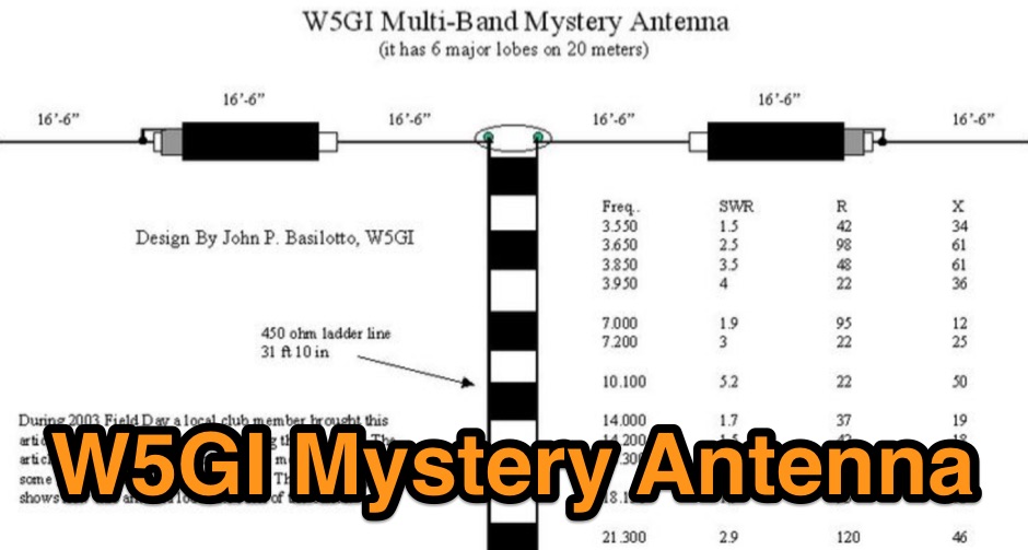 The W5GI Mystery Antenna is a versatile multi-band wire antenna designed for amateur radio operators. It covers frequencies from 80 meters to 6 meters, making it suitable for a wide range of operating conditions. The antenna features a low feed point impedance, allowing for easy matching with most radios, whether or not an antenna tuner is used. Its construction is straightforward, requiring only two vertical supports approximately 130 feet apart, making it ideal for hams without towers. Users have reported excellent performance, particularly on the 20-meter band, where it outperforms similar designs like the G5RV. This antenna is unique in its design, incorporating three half waves in-phase on 20 meters, resulting in a six-lobe radiation pattern. Despite its effective performance, the antenna is challenging to model, which adds to its mystique. The W5GI Mystery Antenna has gained popularity among amateur radio enthusiasts worldwide, with many users praising its ease of construction and effectiveness. Whether you're a beginner or an experienced operator, this antenna offers a fun and rewarding project that can enhance your HF capabilities.
 -
 The G5RV antenna, with an overall length of **31.10m (102ft)**, functions as a 3/2-wave on 20 meters when installed horizontally at 12m (39ft), exhibiting a resonant frequency of 14.150MHz and an approximate resistance of 80 ohms. Its 10.36m (34ft) stub line, designed as a 1/2-wave on 14.150MHz with a 0.97 velocity coefficient, acts as an impedance transformer across other bands, aiming for multiband operation without traps. On 20m and higher frequencies, the G5RV demonstrates improved gain compared to a standard dipole, attributed to the _collinear effect_ from multiple 1/2-waves along the wire. The original design sought a multiband solution for limited spaces, often requiring an Antenna Tuning Unit (ATU) for effective operation across bands like 80, 40, 30, and 20m, particularly with modern solid-state PAs. Variants, such as the F8CI modification, incorporate a 1/4 current balun at the stub line's base for symmetrical-to-asymmetrical transition, known as a _remote balun_. Proper flat-top or inverted-V installation is critical for maintaining symmetry and collinear gain, with inverted-V apex angles below 120° progressively diminishing higher-band performance.
 -
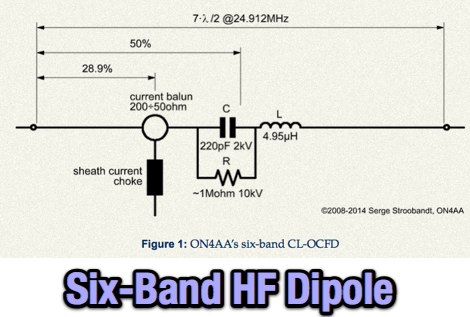 Theory and construction of a novel trapless center-loaded off-center-fed (cl-ocf) dipole or windom antenna for the 80, 40, 30, 20, 15 and 10m hf amateur radio bands
 -
 Sardine Can Antenna. is a BiQuad or Bi circle - wire length each side (8 x 1/4 waves ) 31 mm
 -
 We worry a lot about Standing Wave Ratio (SWR) in amateur radio since SWR is one indication of how well our antenna system is working. Most HF transceivers and antenna tuners have built in SWR meters. SWR is a measure of a transceiver' s output power verses the portion of that power reflected by the antenna system
 -
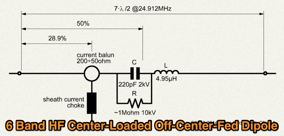 Multiband Center-Loaded Off-Center-Fed Dipole (CL-OCFD) antenna that work on 80m 40m 30m 20m 15m 10m. The Center-Loaded Off-Center-Fed Dipole (CL-OCFD) antenna, developed by Serge Stroobandt, offers a versatile solution for amateur radio enthusiasts, covering multiple HF bands (80, 40, 30, 20, 15, and 10 meters) without the need for an antenna tuner. This innovative design utilizes a capacitor for resonance on the 80-meter band and a resistor to manage static charges. The CL-OCFD enhances bandwidth and simplifies operation, making it a significant advancement on OCF Dipole design.
 -
 Schedules and local radios broadcasting from and to Iraq during war.
 -
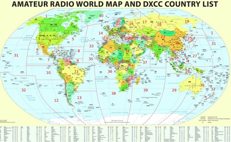 Large picture of a 2011 amateur radio map with DXCC country list
 -
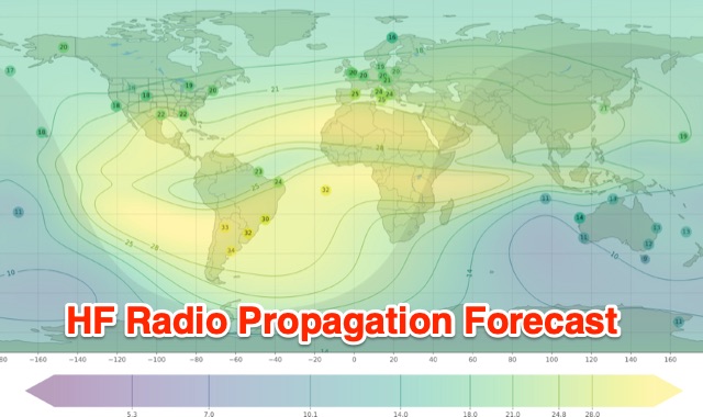 Understanding high-frequency (HF) skywave propagation is crucial for amateur radio operators seeking to optimize long-distance communications. This resource details the fundamental principles of HF radio propagation, including the properties of electromagnetic waves, the characteristics of various HF bands, and distinct propagation modes such as skywave, ground wave, and line-of-sight. It places significant emphasis on the ionosphere's pivotal role in refracting HF waves, explaining how solar activity directly influences ionospheric conditions and, consequently, propagation paths. The resource integrates real-time monitoring capabilities, featuring dynamic charts and data from DX clusters, WSPRnet, and the Reverse Beacon Network, which allow users to track current band activity and propagation conditions globally. It also delves into advanced topics like Near Vertical Incidence Skywave (NVIS) and gray line propagation, providing insights into ionosonde data and various propagation prediction models. The site presents a detailed analysis of solar-terrestrial interactions, geomagnetic indices, and space weather phenomena, illustrating their direct impact on HF communication reliability. Practical tools and applications are highlighted, including real-time QSO planners, online Maximum Usable Frequency (MUF) maps, and alerts for solar flares or geomagnetic storms. The guide systematically breaks down complex concepts into accessible chapters, offering a structured approach to learning about ionospheric regions, diurnal and seasonal effects, and the interpretation of propagation indicators like foF2, MUF, and Lowest Usable Frequency (LUF). This makes it a robust reference for hams aiming to deepen their technical understanding and improve operational effectiveness.
 -
 About numbers stations, and their criptic transmissions, where to listen to them and some audio recording samples by fascinating shortwaves
 -
 Long Waves, Short Antennas, designing antennas for MF and LF communications
 -
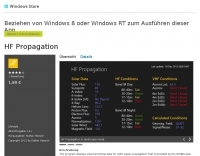 This program displays solar-terrestrial data for radio waves propagation that is provided by the N0NBH web-service.
 -
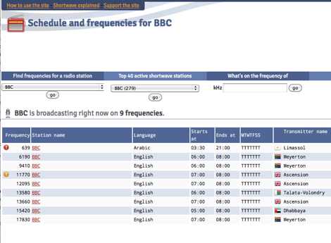 Presents a dynamic, searchable database of shortwave broadcast schedules from around the world, enabling users to locate active stations or plan listening sessions based on scheduled transmission periods and frequencies. The resource details specific station names, such as _Radio Habana Cuba_, _Deutsche Welle_, and _All India Radio_, alongside their operational times and assigned kilohertz frequencies. It also incorporates a distance calculator, which leverages geographical coordinates to estimate propagation paths, though it notes occasional data inaccuracies leading to transmitters appearing in oceanic locations. The platform's development log highlights continuous updates, including the integration of new seasonal schedules like "A24 frequencies" and "B23 schedule," reflecting the fluid nature of shortwave broadcasting. It documents challenges with geolocation services, particularly concerning Google API changes that impacted distance calculations and required user-side browser configuration adjustments for optimal functionality. The site owner, VAXXi, frequently communicates these technical adjustments and database updates, often acknowledging user contributions and donations. Distinctively, the resource provides a historical perspective through its update archives, illustrating the evolution of shortwave listening over more than a decade since its inception in 2011. It also mentions specific events, such as the BBC adding shortwave broadcasts for Ukraine on 5875 kHz and 15735 kHz, demonstrating its responsiveness to global events impacting broadcast schedules. The site's commitment to user feedback is evident in its bug reporting and feature request mechanisms, contributing to its ongoing refinement.
 -
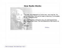 Excellent slides explaining radio and radiowaves generation basics
 -
-
 Presents the _K7AR DX NorthWest Web Cluster_, an online service for amateur radio operators to access real-time DX spots. The resource functions as a web-based interface, enabling users to monitor current band activity, identify rare DX stations, and track propagation conditions across various amateur bands. It aggregates spotting data, making it accessible without requiring a dedicated telnet client, thus simplifying access for many hams. The cluster integrates with the broader DX spotting network, offering a continuous stream of reported contacts. While specific performance metrics are not detailed, such web clusters typically update spots within **seconds** of submission, providing timely information crucial for DXing and contesting. Its utility lies in offering a quick, browser-based overview of the airwaves, comparable to traditional telnet clusters but with enhanced accessibility.
 -
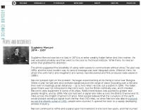 Guglielmo Marconi's foundational contributions to wireless communication began in 1894, inspired by Heinrich Hertz's discovery of radio waves in 1888. His initial experiments at his family home near Bologna quickly demonstrated signal transmission beyond line-of-sight, achieving distances up to **two miles** within a year. Marconi secured a patent in 1896, subsequently gaining interest from the British Admiralty after disinterest from the Italian government. By 1899, Marconi's system facilitated transmissions across the Bristol Channel (nine miles) and the English Channel (31 miles). A pivotal moment occurred in 1901 with the successful _transatlantic transmission_, defying the prevailing belief that Earth's curvature would limit practical range to approximately 200 miles. This achievement catalyzed the rapid development of the wireless industry. Marconi continued refining his inventions and, in 1909, shared the _Nobel Prize_ in physics with Karl Ferdinand Braun for their advancements in radio technology.
 -
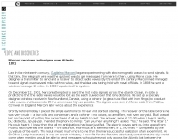 The early 20th century saw significant advancements in wireless communication, culminating in the first successful transatlantic radio signal. This historical account details Guglielmo Marconi's pioneering efforts, from his initial experiments with electromagnetic waves to his patented wireless system in 1900. It describes the technical challenges of long-distance radio transmission, particularly the prevailing belief that radio waves would be lost due to the Earth's curvature over vast distances. On December 12, 1901, Marconi established a receiving station in Newfoundland, Canada, utilizing a _coherer_ and balloons to elevate the antenna. Signals, consisting of the Morse code letter "S" (pip-pip-pip), were transmitted from Poldhu, Cornwall, England. The successful reception of these faint but distinct signals across **1,700 miles** confirmed Marconi's theories, marking an epoch in communication history. This achievement demonstrated the viability of global wireless communication, paving the way for future developments in radio technology.
 -
 Australia's largest range of Electronic Kits & Components In Stock for the Radio Experimenter, ATV, microwaves, HF Band pass filters
 -
 The radio voice of Canada broadcasts daily programs in French, English, Spanish, Arabic, Chinese, Russian and Ukrainian, on shortwaves, satellite and via RealAudio.
 -
 A very brief introduction to microwaves, by Thomas D. Williams, Ph.D., radio amateur WA1MBA
 -

-
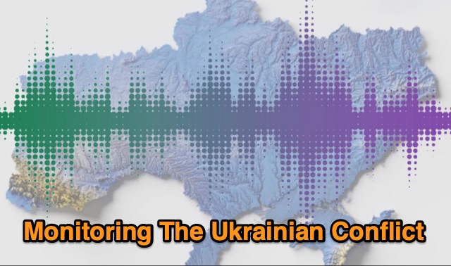 This article reports and collect some frequencies used during 2020 Ukraine war and reported as being used by army forces. HF communications are still a crucial part of military communications and can ben monitored on web sdr radios available on the internet.
 -
 A collection of ad Hoc empirical comments on VHF radio waves propagation by Pete Heins N6ZE
 -
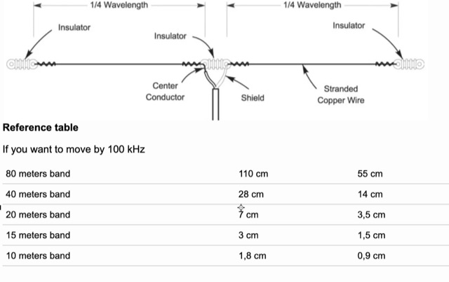 This is a standard calculation method that can help you while tuning dipole antennas, by adjusting wire lengths. This method can be used also when you need to add lenght to your wires, and can be additionally used to quarter waves vertical antennas
 -
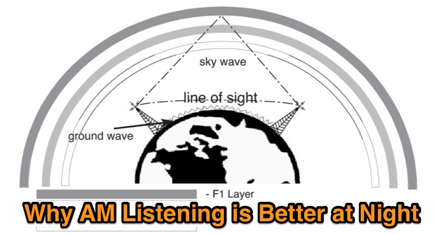 During the night, radio waves can travel a little farther up reaching the F1 layer, offering chances to lister AM Stations that are impossible to hear during the day. Learn more on sky-wave propagation on this article
 -
-
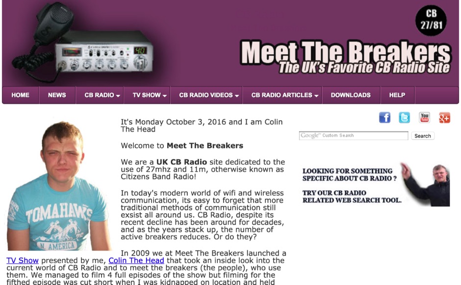 Meet The Breakers is a unique exploration of the CB radio culture in the United Kingdom, hosted by Colin The Head. This series delves into the lives of various CB radio enthusiasts, showcasing their setups, stories, and the vibrant community surrounding this hobby. Each episode features interviews with notable figures in the CB world, providing insights into their experiences and the equipment they use. The program not only highlights the technical aspects of CB radio, such as antennas and signal checks, but also captures the personal stories that make this hobby special. From collectors of rare equipment to modern-day users navigating the airwaves, Meet The Breakers offers a comprehensive look at the diverse personalities that contribute to the CB radio landscape in the UK. Whether you're a seasoned operator or new to the scene, this series is a valuable resource for anyone interested in the world of CB radio.
 -
 NJ2X is a licensed amateur radio operator (FCC Amateur Extra) who enjoys casting electromagnetic waves into the ether. NJ2X pursues many aspects of the hobby including chasing DX, participating in mini-DX expeditions, building equipment and antennas, and papering his shack walls with ARRL awards. NJ2X dedicates this amateur radio oriented site to helping others who also enjoy the greatest of scientific hobbies. The site is suitable for all readers - families, the young, and the young at heart.
 -
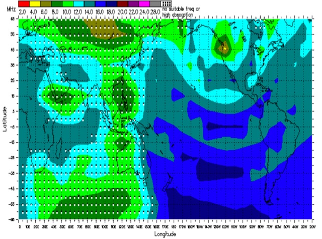 This paper presents the method of calculating the maximum usable frequency (MUF) and field strength of radio waves reflecting 2 times at the F2 ionosphere layer under inhomogeneous conditions of the ionosphere. The comparison between predicted and measured MUF has shown that the proposed method significantly increases the accuracy of calculation MUF.
 -
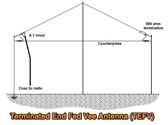 The Terminated End Fed Vee Antenna (TEFV) is a travelling wave antenna with constant current distribution. Unlike traditional resonant antennas, TEFV operates without standing waves, using a terminating resistor for broadband efficiency. With a combination of vertical and horizontal polarization, it offers wide bandwidth from 1.8 MHz to 30 MHz, eliminating the need for a tuner. Key components include a 9:1 unun transformer and a 500-ohm terminating resistor. Grounding and counterpoise enhance performance, and it can handle power losses of up to 30%. TEFV provides an effective, versatile antenna solution for amateur radio and broadcast applications.
 -
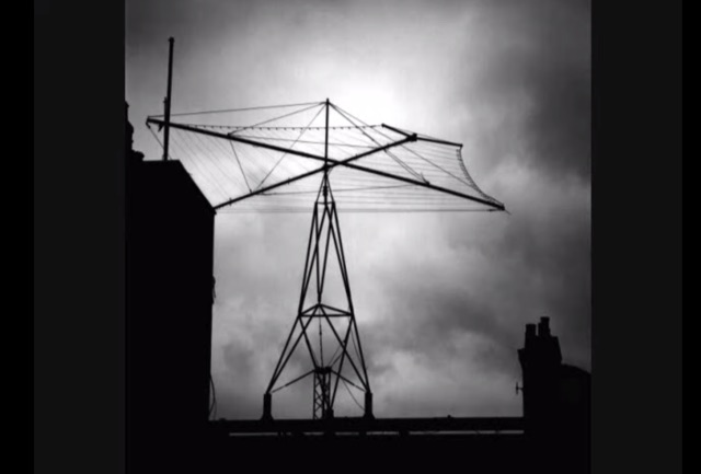 Encrypted messages, fancy technology, spies use them all to communicate, but sometimes the best way to hide is in plain sight. Right now, broadcasting across the airwaves around the world, are automated, anonymous shortwave AM radio stations that most governments won't acknowledge even exist, much less explain
 -
 Heinrich Hertz was the first to send and receive radio waves.
 -
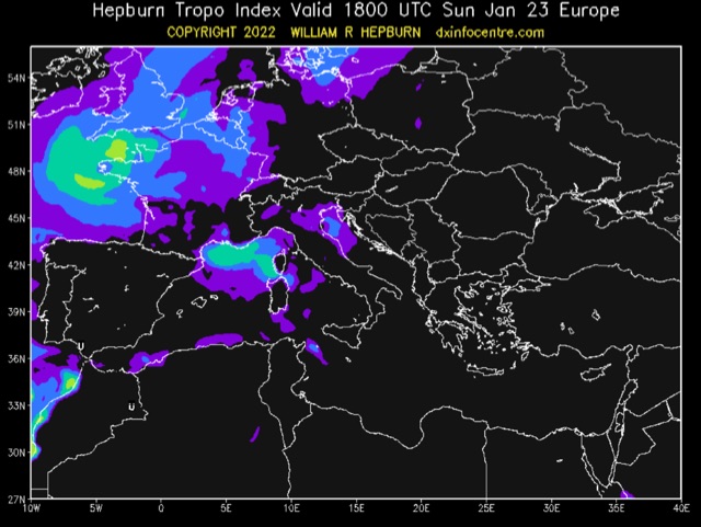 The areas noted in the forecast have the necessary atmospheric conditions to produce tropospheric bending of VHF, UHF and/or microwave radio waves. Tropospheric bending extends the range of radio & TV stations well beyond their normal limit and thus increases interference amongst stations as well.
 -
 Microwaves101 provides an extensive repository of information covering fundamental principles of microwave design, targeting engineers and radio amateurs interested in the higher frequency spectrum. The site features a detailed _encyclopedia_ of microwave terms and concepts, alongside practical design considerations for various components and systems. It serves as a foundational reference for understanding RF propagation, transmission lines, and active/passive microwave circuits. The resource includes numerous calculators for impedance matching, filter design, and other critical RF parameters, facilitating hands-on project development. Discussions on **10 GHz** equipment and **24 GHz** projects highlight practical amateur radio applications, extending to operations up to 134 GHz. Content spans from basic theory to advanced topics like MMIC design and antenna characteristics, supporting both educational and practical endeavors in microwave technology.
 -
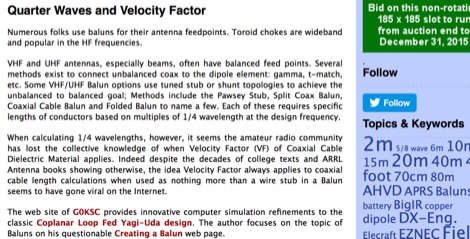 Coax Velocity Factor in Baluns, Does it Matter? Test results show coaxial cable velocity factor does not always enter into stub length calculations especially in the world of Baluns
 -
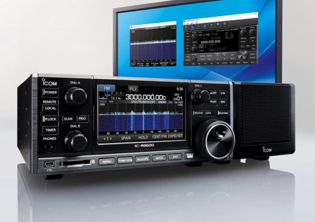 Tuning into the airwaves for new and interesting transmissions has fascinated enthusiasts since the very earliest days of radio. As a result of advances in computer and radio technology, the equipment packed radio rooms of the past are now replaced by scanning receivers sometimes just the size of a mobile phone. What can radio receivers/scanners pick up? What types of radio receivers/scanners are there? What can and cannot be monitored legally? Best practice when using a radio receiver/scanner
 -
 The video showcases the setup of a 300 MHz oscillator, a 100W radiofrequency amplifier, and a dipole antenna for transmitting radio waves, leading to the fluorescence of a nearby light bulb. It demonstrates the presence of standing waves on the dipole antenna and how intensity varies along its length. Additionally, the usage of a copper pipe as a receiving antenna is explored, showing changes in intensity depending on alignment and proximity to the transmitter. Finally, a B field antenna sensitive to magnetic fields is introduced, revealing brightness variations in different orientations. The video offers insightful observations on radio wave transmission and reception phenomena.
 -
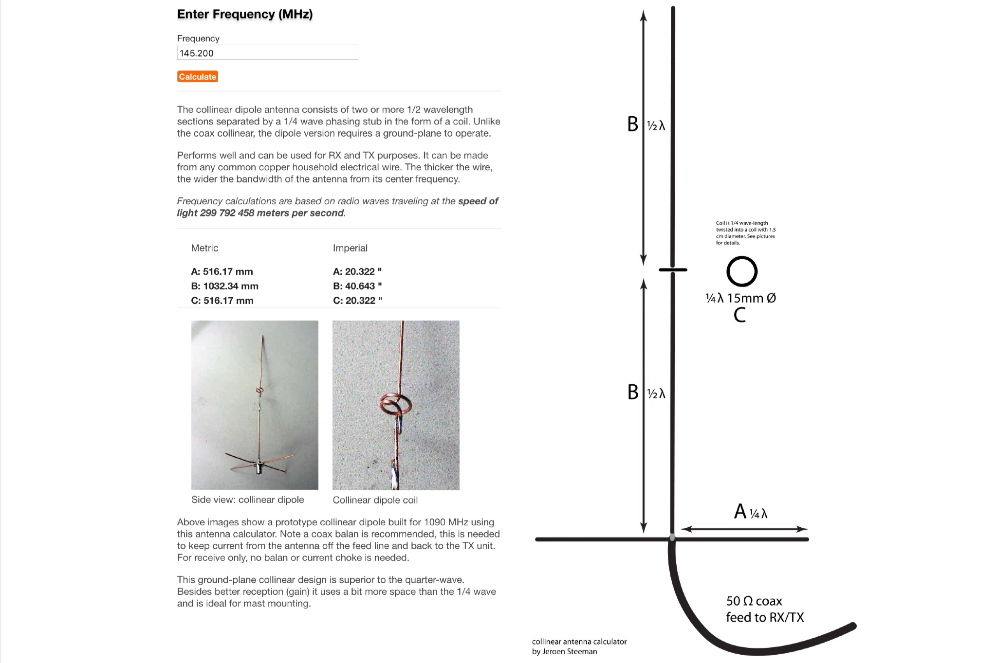 This page offers an online antenna designer to calculate the dimensions for a collinear dipole antenna at a specified frequency. The collinear dipole antenna is constructed with multiple 1/2 wavelength sections separated by a 1/4 wave phasing stub in the form of a coil. It requires a ground-plane to operate and can be used for both receiving and transmitting purposes. The antenna can be made from common copper wire, with thicker wire providing a wider bandwidth. The calculations are based on radio waves traveling at the speed of light. Ideal for ham radio operators looking to build their own antenna for improved reception and transmission.
 -
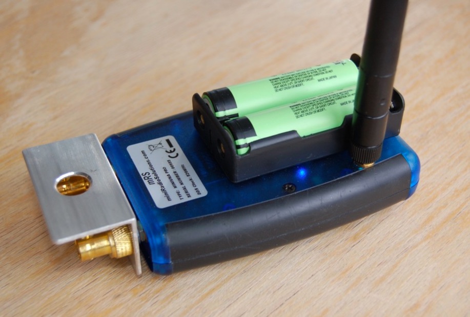 The mini Radio Solutions miniVNA PRO is the only affordable vector network analyser (VNA) I know of that offers remote wireless operation. This is very interesting because it allows to measure the input impedance of HF antennas installed at height without having to deal with coax cable lengths, baluns nor common mode suppression chokes. However, to render the miniVNA PRO truly field proof, it requires a number of significant modifications.
 -
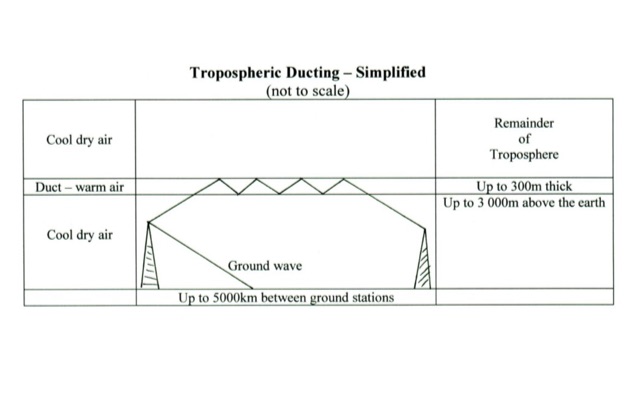 In the spring and during certain climatic events, radio waves can travel long distances due to an atmospheric phenomenon called Tropospheric Ducting.
 -
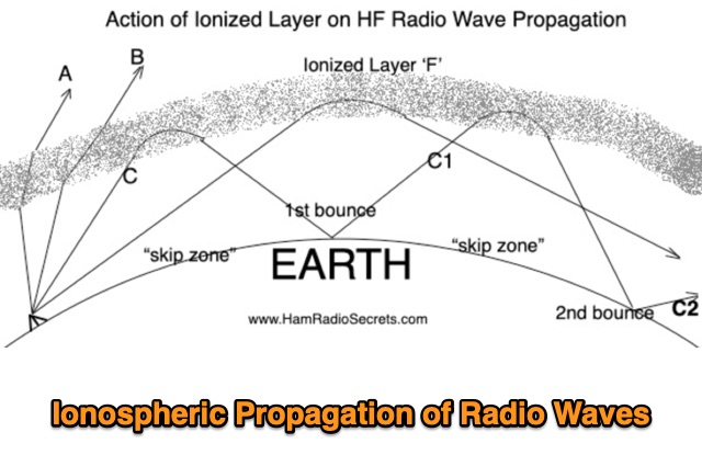 Ionospheric Propagation of Radio Waves in Action, How Do Ionized Layers Form to Enable Ionospheric Propagation of Radio Waves, the foundamental role of F layer, and the role of the other ionized layers
 -
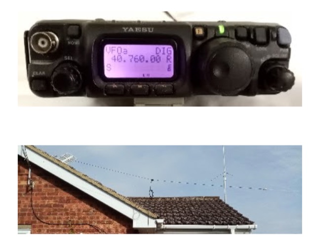 The 8m ISM band, a unique frequency range between 10m and 6m, holds potential for amateur radio enthusiasts, yet it remains largely unallocated. This spectrum offers fertile ground for research and self-training. The author's experience with low-power transmissions and WSPR testing highlights the band's capabilities and the need for a narrow, speech-free amateur allocation to encourage experimentation. Discover the world of 8m ISM radio exploration and its future possibilities.
 -
 This PDF file provides detailed information on HF propagation for ham radio operators. It covers the principles of how radio signals travel over long distances, including factors that affect signal strength and propagation. The content is useful for hams looking to improve their understanding of radio communication and optimize their transmissions. Whether you're a beginner or an experienced operator, this resource offers valuable insights into HF propagation that can enhance your communication skills and efficiency on the airwaves.
 -
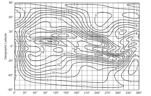 Come learn why it is very difficult to predict propagation on the top band. Ionospheric Variability, Time Variations of Ionospheric Parameters, Atmospheric Gravity Waves, Ionospheric Absorption and The Role of Negative Ions.
 -
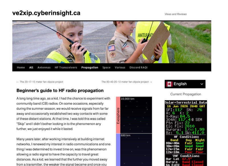 High Frequency (HF) radio propagation, particularly the phenomenon of "Skip," which enables long-distance radio contacts, is thoroughly explained for newcomers to the amateur radio hobby. The article begins by defining essential terms such as _radio signal_, atmosphere, troposphere, stratosphere, mesosphere, thermosphere, exosphere, and aurora, setting a foundational understanding for subsequent discussions. A significant portion of the content focuses on the ionosphere, identifying it as the primary driver of HF propagation. Its structure, including the D, E (E1, E2, E3), and F (F1, F2) layers, is detailed, along with how solar radiation influences these layers to refract radio waves back to Earth. The concept of "The band is opened!" is introduced, specifically noting refraction around **21 MHz**. The guide also touches upon ground waves, space waves, and temperature inversions affecting VHF/UHF propagation, contrasting them with the dynamic nature of ionospheric HF propagation. Factors like antenna polarization, takeoff angle, and the sun's solar cycle are mentioned as critical influences on signal path, with examples like 80-meter band propagation after sunset and 40-meter/20-meter bands offering near-constant propagation.
 -
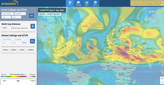 This website explains signal variations on a local radio net by tracking the foF2, a measure of ionosphere's ability to reflect radio waves. The website shows daily foF2 variations and how it affects Near Vertical Incidence Skywave (NVIS) propagation for local nets. It also considers D-layer absorption affecting lower bands and F2 MUF distance for long-distance communication. Additionally, the website tracks foEs for E-layer propagation and an EPI index for predicting Es chances.
 -
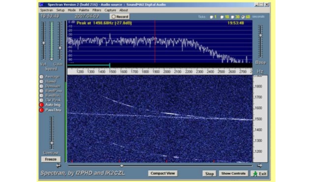 Getting started with Aircraft scatter, defined as the process of scatter radio waves of the body of a traveling aircraft in order to enhance the distance possible to bridge on VHF, UHF and microwaves. The ACS path, Equipment requirement and Operating techniques
 -
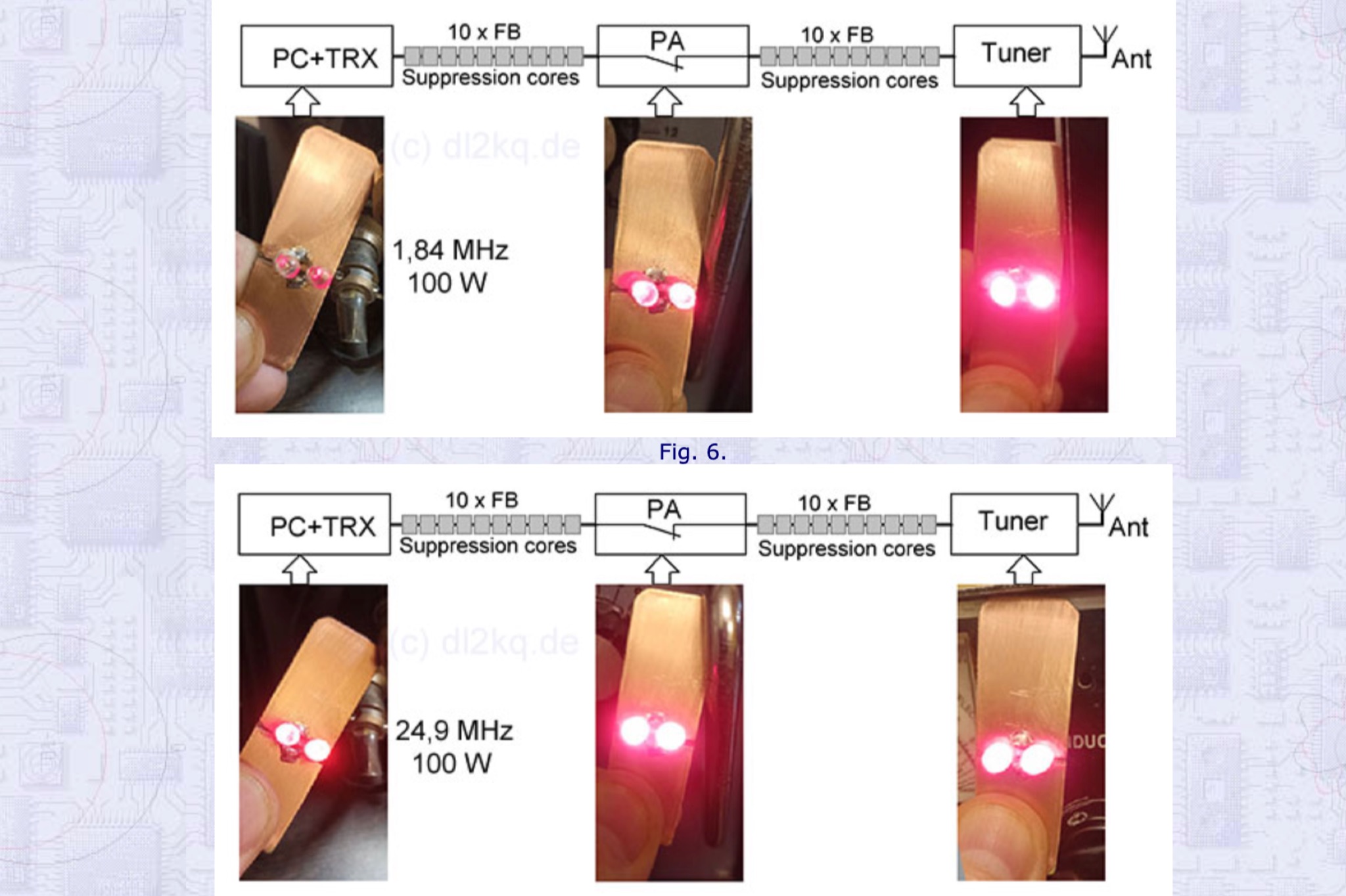 Detecting stray RF voltages on station grounds, chassis, and interconnecting cables is crucial for preventing program and hardware failures in the shack. This article details the construction and application of an LED RF V-probe, which offers significantly higher sensitivity compared to conventional neon lamp indicators. The probe leverages two specific properties of modern red LEDs: their ability to glow at microampere currents and their rectification capability at frequencies up to tens of megahertz. The design features a simple circuit with two LEDs, allowing for indication of both positive and negative RF voltage half-waves. The minimum detectable RF voltage is approximately 2 V, a substantial improvement over the 40-60 V threshold of neon bulbs. The resource illustrates the probe's physical construction on a PCB and provides a direct comparison demonstrating its superior sensitivity in detecting RF fields near a coil. Two operational modes are described: a non-contact mode for high RF voltages (above 15-20 V) and a direct-contact mode for measuring lower RF voltages, with a safety caution for the latter. Practical examples show the probe's use in analyzing RF voltage distribution across a radio station setup at 1.84 MHz and 24.9 MHz, revealing insights into common-mode current issues and the effectiveness of mitigation strategies like adding radials.
 -
 Radio wave propagation describes how radio waves travel from one point to another, classified as ground waves, skywaves, and free space propagation. Ground waves propagate over the earth's surface in low/medium frequencies, bending around obstacles but limited to short ranges. They enable AM/FM broadcasting and military submarine communication.