Search results
Query: rf problem
Links: 45 | Categories: 0
-
 Antenna Restrictions, Power Restrictions, RFI Problems, or Limited Space keeping you off the air?
 -
 Excellent guide to using ferrite cores for interference suppression. Understanding and Solving RF Interference and Noise Problems by Jim Brown K9YC Audio Systems Group, Inc. PDF File
 -
 Some antenna manufacturers place baluns at the incorrect location in LPDA arrays, or tell you to route the cable incorrectly. This can cause substantial RFI and all sorts of weird problems like RF into house wiring.
 -
 The IC-746PRO is a great rig. But it has a few reliability issues, especially with the earlier-production units. This article addresses four problem areas:. IC151 on the RF Unit. Driver circuit on the PA Unit. HRX-muting circuit on the CTRL Unit. Predriver on the PA Unit.
 -
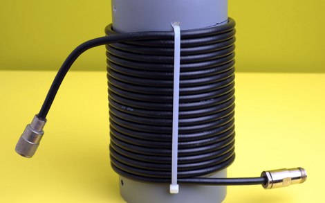 Are you having RF problems in the shack since you put up your HF vertical antenna? This is a common problem with an easy solution.
 -
 Problems using the tuner interface in the ICOM IC7000
 -
 At the moment the most used program is UA1AAF. It is an excellent program written by Boris, UA1AAF, to handle ARI International DX Contest. It can simulate K1EA or N6TR workings; it will be possible to connect the RTX to the computer using a standard interface in such a way as to transmit directly in CW from the keyboard; most of the controls are like K1EA's CT and N6TR's TR ; on line help provides almost all the information necessary for using the program. Is possible to insert QSO after the contest. An appropriate utility in included for conversion in ADIF format. The program is very small and therefore works without any problems on any IBM compatible computer with DOS 3.3 and over or Windows 95/98.
 -
 Understanding and solving RF interference problems using ferrite
 -
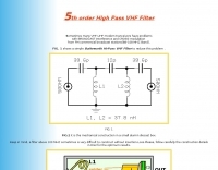 Sometimes many VHF-UHF modern transceivers have problems with BROADCAST Interference and CROSS-modulation from FM commercial broadcast stations this article shows a simple Batteworth HI-Pass VHF Filter to reduce this problem
 -
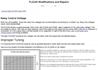 Common problems and improper operations of Yaesu FL 2100 RF power amplifier
 -
 Sherwood Engineering Inc. (SEI) offers a repository of technical presentations and white papers focused on optimizing amateur radio transceiver and receiver performance. Content includes detailed analyses of _roofing filters_, transmitted IMD, and receiver characteristics, with specific discussions on products like the Drake R-4C and Icom IC-781. Presentations from events such as Dayton Contest University (2008-2014) cover topics like "How To Optimize Rig Performance," "Transceiver Performance: 10 Years of Change," and "Choosing a Transceiver: Far from Simple." Additional white papers address HF mobile antenna efficiency, ground screen alternatives to buried radial systems, and common receiver problems with solutions. The site also provides historical product information for items like the SE-3 MK IV synchronous AM detector and various 455 kHz mechanical and crystal filters, though many products are no longer in production. Receiver test data and alignment tips for the R-4C are also available, offering insights into rig modifications and performance enhancements.
 -
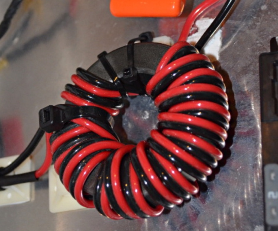
 The intrepid newcomer encounters common mode problems in a mobile environment. Implementing some common mode chokes will be possible to reduce interferences
 -
 This resource details the four primary functions of a ground system: lightning energy dispersion, equipment safety, RF return path provision for end-fed antennas, and management of induced RF currents. It clarifies that a ground system's effectiveness varies depending on its specific function, noting that a good lightning ground might not be an effective RF ground. The content emphasizes that proper antenna system design, including baluns and appropriate feedline lengths, often negates the need for an RF station ground to mitigate common mode currents or RFI in the shack. The article quantifies lightning energy, stating its peak is in the dozens or hundreds of kilohertz, with damaging energy extending to hundreds of megahertz, and currents reaching thousands of amperes. It recommends solid, wide, smooth copper surfaces for ground leads to achieve low impedance across a wide frequency range. The author, W8JI, shares practical insights from his station, which includes two 300-ft towers and four 130-ft wire verticals, detailing his use of common point grounds and _DX Engineering RR-8 HD_ antenna switches for lightning protection without coaxial surge protectors. Specific examples of antenna systems prone to common mode current problems are listed, such as random wire antennas without proper feedline lengths and off-center fed dipoles. The text also explains how a ground screen or radial system can reduce local noise sensitivity for vertically polarized antennas by covering the lossy earth.
 -
 Examines the Icom IC-2100H 2-meter mobile transceiver, detailing its operational characteristics and user experience. The review highlights the clear, easy-to-read display with internal labels, the button-filled microphone's functionality, and the rig's physical construction, including its weighty heat-sink and lack of a cooling fan. It also discusses memory programming, the unique amber-to-green backlight color options, and the radio's performance against _intermodulation_ in urban environments, noting it performs "pretty darn good" compared to other rigs. The analysis delves into a significant low-voltage cutoff problem, where the microphone ceases to function below approximately **12.6 VDC**, rendering the radio receive-only or causing it to stick in transmit. The author describes testing the voltage cutoff, observing it fluctuate from _12.38 VDC_ to 12.69 VDC. An update from Icom involved a "factory update" to the CPU's control code, which is strongly recommended for early-serial number units to prevent operational failure in low-power emergency scenarios.
 -
 Telephone EMI, questions and answers on how to solve interference problems to phone lines
 -
 Why all the mystery surrounding baluns ? To use or not to use baluns
 -
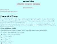 Article on tubes and their usage in power amplifiers design. Explain failures of tube in RF power amplifiers, a common problem in the SB-220 SB-221, TL-922 and other amplifiers.
 -
 Installing mobile radios in your new megabucks car can be a frightening proposition - especially if RF from your rig could damage your shiny new roadster
 -
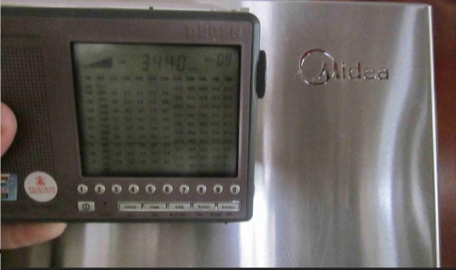
 The _Sci.Electronics FAQ: Repair: RFI/EMI Info_ document, authored by Daniel 9V1ZV, provides a detailed analysis of computer-generated RFI/EMI, focusing on its impact on radio reception. It identifies common RFI sources such as CPU clock rates (e.g., 4.77 MHz to 80 MHz), video card oscillators (e.g., 14.316 MHz), and even keyboard microprocessors, all of which generate square-wave harmonics across HF and L-VHF regions. The resource outlines a systematic procedure for pinpointing RFI origins, including disconnecting peripherals and using a portable AM/SW receiver with a ferrite rod antenna to localize strong interference sources. The document categorizes RFI mitigation into shielding, filtering, and design problems, offering practical solutions for each. It recommends applying conductive sprays like _EMI-LAC_ or _EMV-LACK_ to plastic casings of radios, monitors, and CPUs to create effective Faraday cages, emphasizing proper grounding and avoiding short circuits. For filtering, the guide suggests using line filters, ferrite beads, and toroids on power and data lines, and small value capacitors (e.g., 0.01 uF for serial/parallel, 100 pF for video) to shunt RFI to ground. It also discusses the use of bandpass, high-pass, low-pass, and notch filters on the receiver front-end or antenna feed to combat specific in-band noise.
 -
 Operating a ham station often involves encountering radio frequency interference (RFI), RF feedback, or RF burns, which are frequently misattributed to poor equipment grounding. This resource meticulously dissects these assumptions, asserting that RF grounds on the operating desk often merely mask more significant system flaws. It identifies five primary causes for RF problems, including antenna system design flaws, proximity of the antenna to the operating position, DC power supply ground loops, equipment design defects, and poorly installed connectors or defective cables. The content emphasizes that issues like "hot cabinets" or changes in SWR when connecting a ground indicate substantial RF flowing over wiring or cabinets, a phenomenon known as common-mode current. The article provides detailed explanations of common-mode current generation, particularly from single-wire fed antennas like longwires, random wires, and OCF dipoles, which inherently present high levels of RF in the shack. It also illustrates how vertical antennas, lacking a perfect ground system, can excite feed lines with significant common-mode current. Through simulations, the author demonstrates how a dipole without a proper _balun_ can cause RF problems at the operating desk, showing current patterns and voltage distributions on feed line shields. The discussion extends to the proper application of _RF isolators_ and _ferrite beads_, clarifying their role in modifying common-mode impedance on cable shields and cautioning against their use as a band-aid for fundamental system defects. The resource advocates for correcting the actual source of RF problems, such as antenna system issues or poor connector mounting, rather than relying on internal shack grounding or isolators. It highlights that properly functioning two-conductor feed lines, like coaxial or open-wire lines, should result in minimal RF levels at the operating position, even without a desk RF ground. The author shares personal experience, noting that his stations since the late 1970s have operated without RF grounds at the desks, relying instead on proper antenna system design and feed line integrity.
 -
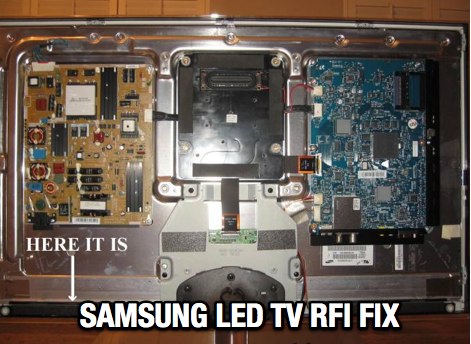 A workaround to common RF interference on Samsung TV LED causing several issues like changing channel, swithcing to demo mode, or changing volume.
 -
 Mobile RFI, often manifesting as persistent noise in the receiver even with the antenna disconnected, frequently originates from the vehicle's power supply system. This guide details systematic troubleshooting steps, beginning with isolating the radio from the car's 12-volt supply to confirm the power system as the noise source. It emphasizes the critical importance of drawing power directly from the battery using **heavy gauge wire**, bypassing the fuse block to leverage the battery's natural capacitance for RFI suppression and ensuring a solid RF ground. Proper routing of power lines through the firewall is also covered, advocating for dedicated grommeted holes to prevent inductive coupling from other wiring harnesses. The article stresses the necessity of fusing both positive and negative leads from the battery, a crucial safety measure to prevent damage to the rig and mitigate high-current risks should the battery's engine block ground become compromised during service. Addressing **alternator whine**, a common high-pitched noise that varies with engine speed, the resource suggests checking battery connections and the alternator-to-battery harness for looseness or corrosion. It also mentions the utility of adding an external RF noise suppression capacitor in parallel with the alternator's internal capacitor for enhanced filtering, and the effectiveness of commercially available in-line power supply filters.
 -
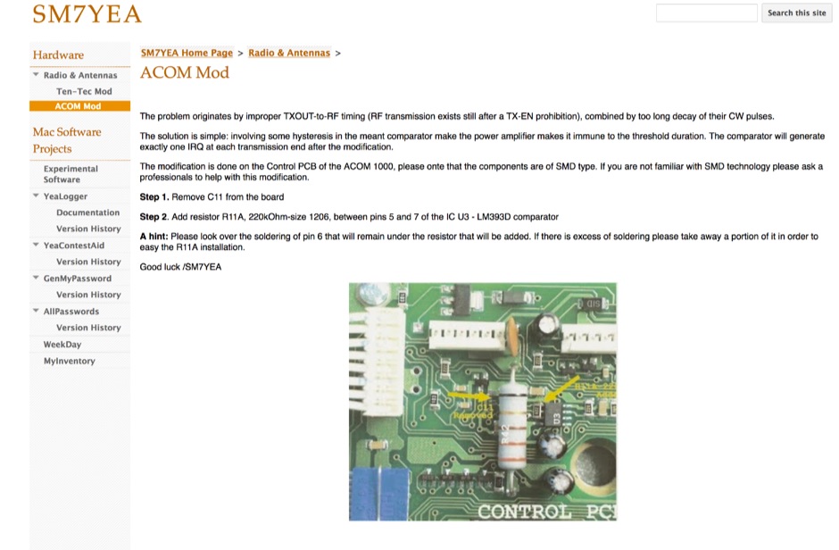 The problem originates by improper TXOUT-to-RF timing (RF transmission exists still after a TX-EN prohibition), combined by too long decay of their CW pulses.
 -
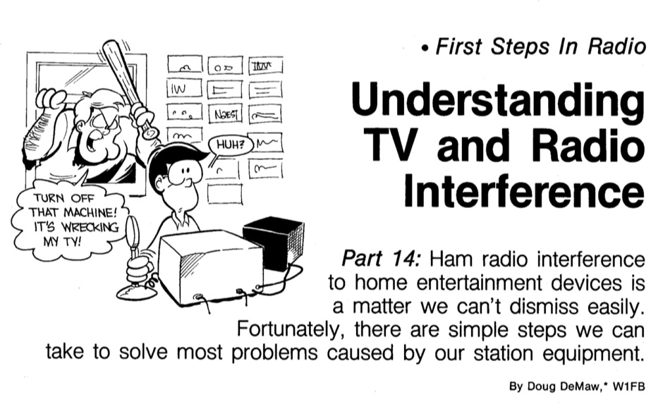 Simple steps you can take to solve most problems caused by station equipment
 -
 1500 watts PEP SSB is the power handling capability of the MFJ-989C HF Antenna Tuner, a popular choice among amateur radio operators. Users have shared a wide range of experiences, with some praising its durability and performance over decades of use, while others criticize its build quality and accuracy. The tuner features a built-in dummy load, SWR-wattmeter, and a balun for balanced line feeders, making it versatile for various antenna setups. However, discrepancies in RF power readings and SWR measurements have been noted, with some users finding the dual scale meter to be off by about 20% compared to a Bird wattmeter. Long-term users report that the MFJ-989C performs well with proper antenna setups, but caution against tuning at high power without initial adjustments at lower power levels. Some have experienced issues such as arcing when exceeding 400 watts, while others have had no problems even at higher power levels. The roller inductor and capacitors are functional, though some users have had to perform maintenance like tightening screws or cleaning components to ensure reliable operation. Despite mixed reviews, the MFJ-989C remains in production, suggesting continued demand. It's a tuner that requires careful handling and possibly some DIY fixes to achieve optimal performance.
 -
 Common problems of the 572B tubes often used in many RF Power Amplifiers
 -
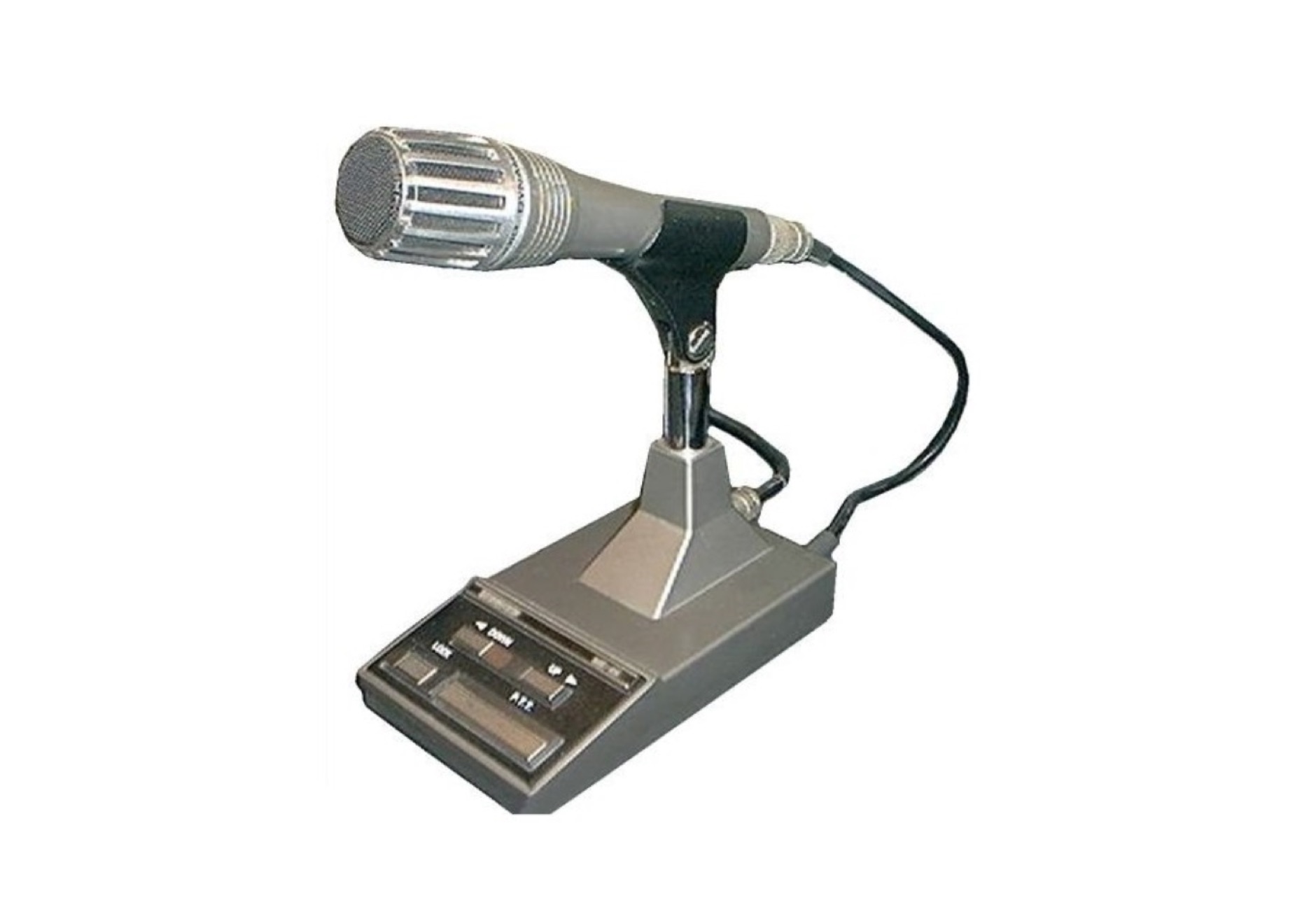 The Kenwood MC60A with preamp, suffers from RF feedback, a search on the web reveals the extent of the problem. This document explain how to fix this problem.
 -
 Nearly half of all reception problems are due to deficiencies or faults in the television receiver, the aerial lead or the aerial. This article will help you to check whether the problem you are having is due to one of these causes.
 -
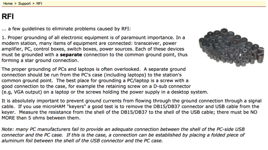 An article by microHam about guidelined to eliminate problems caused by RFI
 -
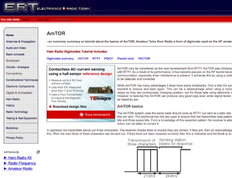 AmTOR may be considered as the next development from RTTY. AmTOR was introduced to overcome the problems with RTTY. As a result of its performance, it has become popular on the HF bands because it gives more reliable communication, especially when interference is present. It achieves this by using a coding system that allows errors to be detected and corrected.
 -
 Transmitting operations in the 50-54 MHz range offer some unique problems that over the past 50 years have stymied station owners, forcing them to tolerate quiet hours and hostility from family and neighbors attempting to enjoy other electronic services.
 -
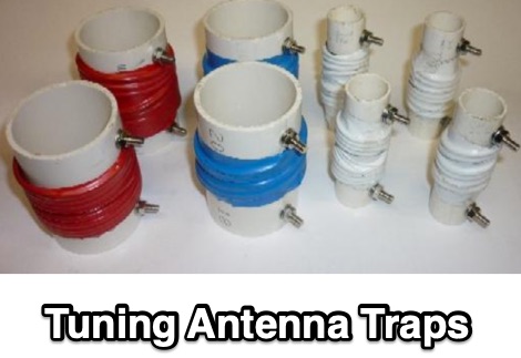 The problem with making your own trapped HF antennas is usually getting the coaxial traps tuned to frequency. This article explains a method using a RF signal generator at +10dBm output into the coaxial trap.
 -
 How to solve RFI problems caused by the charge controller, which is a PWM type charge controller, that generates a lot of EMI interference
 -
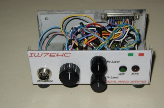 The use of an isolation interface between the radio and the pc is higly recommended,in order to avoid the problems that could be caused from ground loops. This project includes schematic and assembly instructions
 -
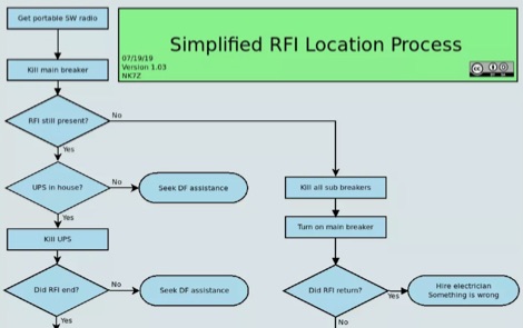 I have RFI, now what– Locating it. This article is the first of a three parts article, that covers the problem of locating the RFI source. Author make use of an SDR receiver to locate RFI emissions. Ai interesting RFI location process diagrams helps on following the various phases, permitting the discovery of almost 75% of the RFI issues.
 -
 Integrating a **160-meter vertical wire antenna** with an existing 80-meter Yagi system presents unique challenges for Top Band operation. This project outlines the author's experiences with seasonal antenna removal and reinstallation, a necessary task for agricultural land use. It details specific issues encountered, such as incorrect coil sizing and relay configuration problems, providing practical insights into common pitfalls. The article describes the iterative tuning process, comparing **NEC model** predictions with actual on-air performance. It emphasizes the importance of precise measurements and adjustments to achieve optimal resonance and impedance matching. The author shares lessons learned from troubleshooting, including the impact of ground system integrity and feedline considerations. Concluding with an antenna checkup, the resource addresses long-term maintenance aspects, including galvanic corrosion prevention and general upkeep for reliable operation.
 -
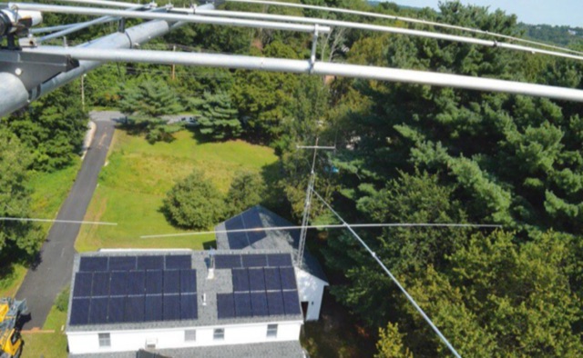 If you are having problems with RFI from Solar Panels this document from QST provides useful advice. According to this article it is possible to prevent and mitigate RF interferences, with your amateur radio equipment, by suppressing the RF either in the shack and to the solar power infrastructure.
 -
 The Smith Chart, named after its inventor Phillip H. Smith, is a graphic tool used to solve transmission line problems in the field of ham radio operations. By using the Smith Chart, ham radio operators can determine the feed point impedance of an antenna, design impedance-matching networks, and optimize power transfer between a source and its load. The chart consists of resistance and reactance circles, providing a visual representation of complex mathematical relationships related to transmission line operations. Understanding and utilizing the Smith Chart is essential for hams looking to enhance the performance of their RF circuitry.
 -
 This fall/winter 2 events has happened at about the same exact time. I finally got around to putting up an end fed long wire for 80M (and maybe 160M) The fridge big the bullet and we ended up purchasing a new fridge.
 -
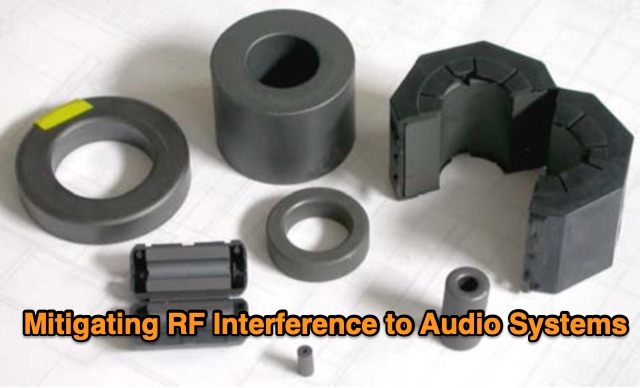 In this study, the author builds upon Muncy's research, demonstrating that radio-frequency current on cable shields affects audio systems through the "pin 1 problem" and shield-current-induced noise (SCIN). An enhanced equivalent circuit for ferrite chokes is proposed, addressing dimensional resonance and inductor self-resonance. Field tests confirm that chokes reduce interference across 500 kHz to 1,000 MHz. Guidelines for diagnosing and mitigating EMI from various sources are provided for product development and field installations.
 -
 Digital modes troubleshooting can be complex, even with devices like Digirig, which are designed for ease of use. This guide provides solutions for common setup issues in ham radio digital modes, applicable to Digirig and similar interfaces. Key troubleshooting tips include isolating problems, restoring previous configurations, ensuring correct USB and audio connections, and configuring software and hardware settings properly. Community forums offer additional support for specific issues.
 -
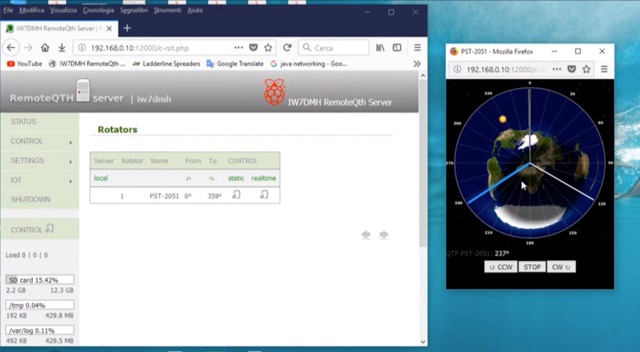 If you are a RemoteQth server user, and own a Prosistel rotor, you will have to deal with the problem of remoting your rotor. The solution suggested by RemoteQth is to build the K3NG interface that allows you to control any types of rotor.
 -
 A homemade oak plank drive-on mast holder proved functional but heavy and cumbersome. A lighter, compact commercial version from Amazon seemed ideal but couldn't fit the preferred Jackite pole. Costly alternatives, like a $100 mast holder from Three Mosquitoes Gear, were impractical. The solution came through DIY ingenuity: a piece of 2" PVC and hose clamps, repurposing materials already on hand. This simple, effective design perfectly accommodated the Jackite pole, demonstrating the power of resourceful problem-solving.
 -
 The article details how to eliminate Radio Frequency Interference (RFI) from the Behringer HA400 headphone amplifier when used in ham radio setups. While the HA400 is praised for its quality and affordability, it was not designed for RF environments, causing distortion when used with a 500-watt radio station. Initial attempts using clamp-on ferrites on the headphone and power cables only partially resolved the issue. Upon opening the unit, the author discovered the circuit lacked RF bypassing components. The solution involved installing 0.1μF (104) capacitors at key points in the circuit: the power supply input, audio circuits, and op amp inputs. This modification, combined with the external ferrites, completely eliminated the RFI problem, making the unit suitable for ham radio operations.
 -
 This resource details **cooling modifications** for Ameritron AL82, AL1200, and AL1500 HF amplifiers, specifically addressing heat issues encountered during high-duty-cycle digital mode operation. The author, WD4NGB, observed excessive heat in the tank area and band switch on an AL82, attributing it to insufficient exhaust over the 3-500 tubes and a complete lack of exhaust over the tank area. The modifications aim to prevent common failures such as damaged band switches and deformed insulating materials by increasing airflow and exhaust area. The page describes adding five holes to the chassis for enhanced cooling to the band switch and tank area, alongside enlarging the exhaust area over the inner 3-500 tube and the tank area on the amplifier cover, utilizing expanded metal for safety and RF shielding. The original cover featured 26.25 square inches of exhaust; the modified version significantly increases this to 48.5 square inches over the tubes and introduces an additional 15 square inches over the band switch. These changes are intended to resolve heating problems encountered during heavy, 100% duty cycle use in modes like RTTY or long SSB contests, which typically generate substantial heat. The article also discusses upgrading to a higher output fan, such as the G2E085-AA05-21, and modifying tube sockets for improved airflow and reduced back pressure, citing Tom Rauch (W8JI) of CTR Engineering as a source for parts.