Search results
Query: rg 58 coax
Links: 39 | Categories: 0
-
 This article describes how to make a quadrifilar helix (QFH) antenna easily, from inexpensive materials: uPVC plumbing pipe and RG-58U co-axial cable. A low-cost, easy-to-build Quadrifilar Helix (QFH) antenna for weather satellite reception using uPVC plumbing pipe and RG-58U coaxial cable. Unlike traditional designs requiring copper pipe and plumbing skills, this approach enables construction with basic tools and minimal technical expertise. The antenna's shorter, wider proportions favor higher elevation angles, reducing interference from horizon-level pager transmitters. Electrical connections are simplified at the antenna's apex, with the coaxial cable forming the radiating elements. Testing demonstrated consistent signal strength throughout satellite passes, proving effective weather satellite reception is achievable without precision engineering to sub-millimeter tolerances.
 -
 The Flower Pot Antenna project details a portable dual-band antenna primarily operating on 10 meters, with secondary resonance near the 30-meter band. Construction involves winding RG58 coaxial cable uniformly around a large plastic flower pot, approximately 70cm high with a 60cm top diameter. The design eliminates the need for radials, contributing to its compact and lightweight nature. Key construction steps include soldering the inner conductor to the shield at one end of the wound cable and connecting the wound cable's shield to the rig cable's inner conductor at the base. An LC network, comprising a variable capacitor (0-200pF) and an inductor (10 coils, 5cm diameter, 2mm wire), is inserted between the wound cable's inner conductor and the rig cable's shield. Tuning is performed with an antenna analyzer, adjusting cable length and the variable capacitor for optimal impedance on 10 meters. The antenna performs effectively when installed horizontally.
 -
 This drawing shows a simple 10 meter wire J-pole antenna designed for 28.4 MHz. It is a vertical, end-fed Zepp-style antenna made from common materials and intended for easy home construction. The main radiating element is a straight length of stranded copper wire, either 14 or 18 gauge, cut to about 16.5 feet. At the top, the wire is supported by an insulator, allowing the antenna to be hoisted vertically. The matching section is made from 450-ohm ladder line, approximately 7 feet 9.5 inches long, and shorted at the bottom. This matching stub transforms the impedance so the antenna can be fed with coaxial cable. The feed point is tapped about 6 inches above the bottom of the stub, with the shield and center conductor connected at the proper points. A choke balun is formed with five turns of RG-58 coax in a 4-inch diameter loop to help reduce unwanted RF on the feed line. The drawing notes that this antenna has about 0 dBd gain, similar to a dipole, but offers an omnidirectional pattern and low-angle radiation when installed high. Its main advantage is practical performance, simple construction, and effective coverage for 10 meter operation.
 -
 The Double Bazooka Dipole is a very efficient single band antenna which is very quite, and does not require the use of a balun. This antenna consists of coax (RG58) or other 50 ohm type with the shield split at the center and the feedline attached to the open ends
 -
 Demonstrates the construction and performance of an updated ZS6BKW multiband dipole, a variant of the _G5RV_ antenna, specifically designed for HF operation. The article details a real-world installation using 13.5m copper wire elements and 12.2m of 450 Ohm ladder line, configured as a sloping inverted-V with the apex at 10m and ends at 4m above ground. It covers the critical aspect of impedance matching, incorporating an 8-turn choke balun at the feedline transition to RG-58U coax to mitigate RF common mode current. Measurements confirm favorable SWR readings below **1.3:1** on 7.1 MHz, 14.11 MHz, 18.06 MHz, and 24.8 MHz, indicating effective resonance across 40m, 20m, 17m, and 12m bands. The installation also shows usable SWR dips on 3.55 MHz (5:1), 29.02 MHz (2:1), and 50.84 MHz (3:1), extending its utility to 80m, 10m, and 6m with an antenna tuning unit. Initial on-air results report clear reception of stations over **5000km** away, validating its DX potential.
 -
 The Coax trap program computes design parameters for the construction of coaxial traps for HF usage. Typically these are constructed from PVC tube and RG58/59 coax
 -
 A simple multi-band magnetic loop antenna designed for 20, 30 and 40 metres, made from 16 feet of RG58 coax cable. The performance is impressive for its size but not meant to replace a Yagi. The antenna features a tuning head, matching unit, tuning capacitors, band change switch, and matching transformer. The feedpoint is at the bottom of the loop. The document provides detailed instructions on assembly and operation.
 -
 A rotary trapped-dipole for 17 and 20 meters, as described by IZ7ATH, presents a practical solution for multi-band HF operation. The author, Talino, recounts his experience building this antenna for IK7ZCQ, detailing the evolution from an initial concept involving a grounded-driven element and gamma-match to a direct-fed, non-grounded design. His pragmatic approach, adapting available materials, is evident throughout the construction narrative, particularly with the use of eight tapered aluminum pipes for the driven element. Construction specifics include precise measurements for the aluminum tubing, with diameters ranging from 30 mm down to 16 mm, and a critical note on reducing tip thickness for weight optimization. The _traps_, initially a concern, are fabricated using 8 turns of RG58 coax on a 27 mm support, tuned to resonate at 18.1 MHz using a dip-meter. Talino emphasizes sealing the traps with RF glue and PVC tape to prevent water ingress, a crucial step for longevity. Field test results, conducted on a 10-meter pole in a clear garden environment, showed an SWR of 1.2:1 on 17 meters and 1.5:1 at 14.200 MHz. While SWR varied slightly when installed at Mario's QTH due to nearby objects, the antenna's performance remained commendable. The final half-dipole length is 46 cm for the 18 MHz tips, and the total weight is under 6 kg, with potential for further reduction.
 -
 OE1MWW monopole antenna made with common RG 58 or RG 213 coaxial cable
 -
 N0KHQ Moxon rectangle for 17 meters, constructed from RG-58 coaxial cable
 -
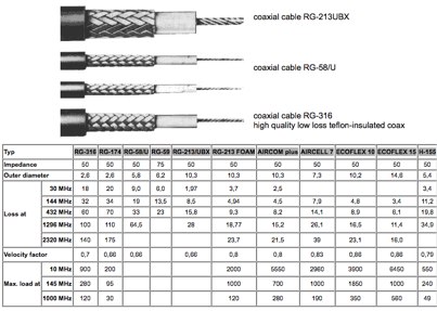 A page with several coax cable characteristics comparison. Includes RG-316 RG-174 RG-58/U RG-59 RG-213/UBX RG-213 FOAM AIRCOM plus AIRCELL 7 ECOFLEX 10 ECOFLEX 15 H-155
 -
 Constructing a Lindenblad antenna for 137MHz NOAA satellite reception involves specific design considerations for optimal performance. The resource details the use of 4mm galvanised steel fencing wire, 300-ohm television ribbon cable, and wood/plastic components for the antenna structure. Key dimensions for a 137.58MHz-resonant antenna are provided, derived from the ARRL Satellite Handbook, specifying s, l, w, and d as 42, 926, 893, and 654mm respectively. The antenna is designed for Right Hand Circularly Polarised (RHCP) signals, requiring the four folded dipole elements to be tilted clockwise by 30 degrees. A significant aspect covered is impedance matching between the antenna's 75-ohm impedance and a typical 50-ohm receiver input. A twelfth-wave matching transformer, constructed from 117mm sections of 50-ohm RG-58 and 75-ohm RG-59 coax with a 0.66 velocity factor, is described. The article also addresses coaxial cable and connector selection, recommending 75-ohm Type-N connectors for RG-6 cable in professional setups and F56/F59 connectors for general use, while strongly advising against PL-259/SO-259 connectors for VHF. Strategies for mitigating Radio Frequency Interference (RFI) are discussed, including antenna placement to shield from local TV transmitters and the use of commercial or DIY band-pass filters, such as cavity resonators or helical notch filters, along with ferrite chokes on coaxial cables. Antenna orientation is explored, noting the Lindenblad's 'cone of silence' directly overhead and its maximized sensitivity towards the horizon. An experimental vertical tilt of 90 degrees is presented as a method to improve overhead reception and reduce interference from strong horizontal signals, particularly relevant in high RFI environments like the Siding Spring Observatory site.
 -
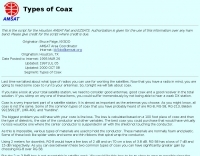 Coax is a very important part of a satellite station. It is almost as important as the antennas you choose. This article discusses choosing coaxial cables for satellite communication, emphasizing factors like line loss. It compares types such as RG-8, RG-58, Belden 9913/9913F, LMR-400, and hardline, highlighting their impact on signal preservation.
 -
 Presents a detailed construction guide for a **Quadrifilar Helix Antenna** (QHA) optimized for 137 MHz, specifically for receiving weather satellite transmissions. The resource outlines the author's experience building previous QHA designs, highlighting challenges with tuning and nulls, and then focuses on a refined design by John Boyer, documented by Steve Blackmore, which proved easier to build and yielded superior reception. The guide provides precise element dimensions, including 1.5m of 32mm PVC pipe for the mast and 8mm soft copper tubing for the helix elements. It specifies lengths for horizontal tubes (190mm, 90mm) and helix elements (903mm, 1002mm), along with instructions for drilling, assembly, and forming a **balun** by wrapping RG58 coax around the mast. The text emphasizes critical steps like ensuring elements are square and twisting in the correct direction to avoid phase issues. It includes references to original QST articles by Buck Ruperto (W3KH) and the WxSat program for decoding satellite transmissions, contextualizing the antenna's purpose. The article concludes with a sample NOAA 12 image from September 1998, demonstrating the antenna's reception capabilities.
 -
 A homemade VHF/UHF vertical antenna made essentially with RG58 coax cable, with a 9 turns choke balun to prevent the shield acting as a RF Radiator.
 -
 The Resonant Feedline Dipole (RFD) HF antenna design utilizes a single piece of coaxial cable and a stranded wire section, forming a 1/4-wavelength radiator. This configuration, based on a 1997 ARRL Handbook design (page 20.17), functions by RF traveling on the inside of the coax shield and returning on the outside, creating the second half of the dipole. A choke wound into the feedline prevents RF current from flowing back down the feedline. Construction details include using RG-58a/u coax for a 75m version, with a 1/4-wavelength section of stranded wire soldered to the center conductor. The document provides choke dimensions for RG-213, RG-8, and RG-58 coax across 3.5 MHz to 28 MHz, specifying cable length and number of turns. Dipole dimensions are also tabulated for frequencies from 3.6 MHz to 28.4 MHz, listing overall length and individual leg lengths. Field tests included deployment near Bryson City at 5 feet off the ground and as a sloper during WCARS Field Day in Asheville, yielding successful local and regional contacts.
 -
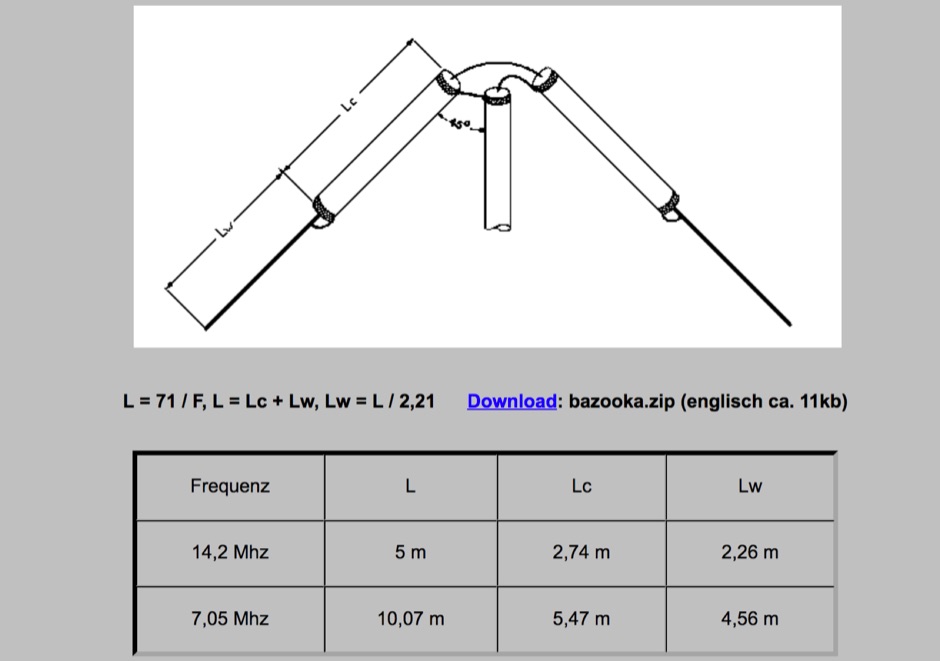 A bazooka antenna design in German with dimensions for 20m and 40m band with RG174 coax cable stronger than the common RG58
 -
 Demonstrates the construction of a 144 MHz turnstile antenna, detailing its design for omnidirectional, horizontally polarized VHF operation. The resource outlines the physical dimensions and materials required, including specific lengths for the radiating elements and the use of _RG-58_ coaxial cable for phasing. It covers the assembly process, emphasizing the critical spacing and connection points to achieve the desired radiation pattern and impedance matching for the _2-meter band_. The article presents measured _SWR_ performance across the 144-146 MHz segment, showing a low SWR of 1.2:1 at 144.5 MHz, which is suitable for general VHF use. It compares the turnstile's performance to a 9-element Yagi, noting the turnstile's advantage in providing consistent signal strength from all directions without requiring a rotator. Practical application for local FM simplex and repeater operations is implied, offering a simple yet effective antenna solution for fixed or portable stations.
 -
 The Double Bazooka Dipole is a very efficient single band antenna which is very quite,and does not require the use of a balun. This antenna consists of coax (RG58) with the shield split at the center and the feedline attached to the open ends.
 -
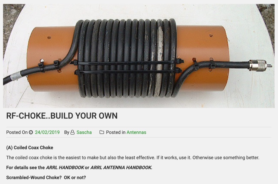 How to make an effective RF Choke. The coiled coax choke is the easiest to make but also the least effective. This article includes some general guidelines for winding coax chokes on a 10cm PVC pipe using RG-58 or RG-213 coax cable.
 -
 1.5 dB of matched line loss can be calculated for a given transmission line using this online tool, which employs a model calibrated from empirical data. The calculator allows radio amateurs to input specific transmission line types, such as _RG-8_ or _RG-58_, and then determine the expected signal attenuation. This is crucial for optimizing antenna system efficiency and understanding power delivery to the radiating element, especially for HF and VHF operations where feedline losses can significantly impact performance. Beyond matched loss, the calculator also provides an estimate for mismatched loss if the Standing Wave Ratio (SWR) is specified. This feature helps operators quantify the additional power loss due to impedance discontinuities between the transceiver, feedline, and antenna, which is a common concern in amateur radio installations. Accurate loss calculations are vital for effective station design and for predicting actual radiated power. The tool's utility extends to various operating scenarios, from fixed station setups to portable deployments, aiding in the selection of appropriate feedline lengths and types to minimize signal degradation. Understanding these losses is a fundamental aspect of maximizing the effectiveness of any amateur radio antenna system.
 -
 This web article details the construction of a 4-meter band coaxial dipole antenna, designed for operation between **70.000 MHz and 70.500 MHz**. The resource provides a bill of materials and step-by-step assembly instructions for a half-wave dipole constructed from _RG-58_ coaxial cable. The design specifies a direct 50 ohm feedpoint impedance, eliminating the need for an external matching network. Construction photographs illustrate the stripping and soldering processes for the coaxial cable elements, ensuring proper electrical connection and physical integrity. The article includes specific dimensions for the radiating elements, derived from calculations for the 70 MHz band. The project outlines the physical dimensions required for resonance at 70 MHz, with the outer braid forming one half and the inner conductor forming the other. The feedline connection is directly to the coaxial dipole's center, maintaining a 50 ohm characteristic impedance. While the article does not present SWR plots or VNA sweeps, it focuses on the mechanical construction and dimensional accuracy for achieving a functional 4-meter dipole. The design is intended for fixed station use, with no specific mention of polarization or height above ground, but implies a standard horizontal orientation for dipole operation. DXZone Focus: Web Article | 4m Coaxial Dipole | Construction Guide | 50 ohm Feed
 -
 Sort of similar to the one of the 6m omni. Instead of using twin-lead, this design makes use of a more or less regular double bazooka antenna (coaxial dipole). Your attention shall be drawn to the available standart literature, such as Rothammel. In order to "compute" the dimension, Karl Rothammel mentioned that the total length of the dipole shall be 95% of the free-space wavelength. The short-circuit bridges (closing the folded dipole) are to be placed at a distance-fraction being equal to the velocity factor of the coax cable used, which will be 66% using RG-58 or RG174.
 -
 Over 100 distinct RF connector types are available from AIR802, including popular UHF series PL-259 plugs and SO-239 sockets, designed for a wide array of coaxial cable dimensions. The company specializes in producing connectors compatible with common amateur radio cables like RG-8, RG-213, and RG-58, ensuring reliable signal integrity for antenna systems and shack interconnections. Their product line extends to various coaxial cable types and pre-made antenna cable assemblies, offering ready-to-deploy solutions for hams. AIR802 also provides custom cable assemblies and pigtails, catering to specific installation requirements for transceivers, tuners, and amplifiers. These pre-fabricated options simplify station setup, reducing the need for field termination of connectors. Michael Bryant is the contact for inquiries regarding their range of RF components, which are essential for building robust and efficient amateur radio stations.
 -
 Coaxial cable stripping for PL-259 connectors requires precise measurements to ensure optimal RF performance and mechanical integrity. For RG-8X, the outer jacket is stripped 1/2 inch, the braid 5/16 inch, and the dielectric 1/8 inch, leaving the center conductor exposed. RG-58 preparation involves a 1/2 inch jacket strip, 1/4 inch braid strip, and 1/8 inch dielectric strip. These specific dimensions facilitate proper soldering and crimping, minimizing impedance discontinuities at the connector interface. Different coaxial cable types, such as RG-8 and RG-213, necessitate varied stripping lengths due to their construction. The _PL-259_ connector, a common UHF type, relies on these exact preparations for a secure fit and low-loss connection. Incorrect stripping can lead to high SWR, RF leakage, and mechanical failure, impacting overall station efficiency. The guide details these critical dimensions for several popular coax cables. Using a dedicated _coax stripper_ tool or precise measurements with a utility knife improves consistency.
 -
 One of the featured products, the V350 CAMP, is a multiband vertical antenna covering 6 to 80 meters, priced at R$ 799,90, demonstrating the range of ready-to-use solutions available. The inventory includes various antenna types such as **HF**, **VHF**, and **UHF** designs, along with dual-band options like the J-Pole Dual V/UHF for R$ 235,00. For those building their own arrays, the store stocks essential components like element holders, clamps, junction boxes, and aluminum plates, alongside specialized items such as the KIT Isolador Central Dipolo - 01DX for R$ 99,90. The shop also provides a comprehensive selection of installation hardware, including diverse antenna mounts, PTT supports, and various coaxial cables like RG58 and RG213, with prices up to R$ 849,90 for RG213. Connectors such as UHF male PL259 and various adapters are readily available, ensuring compatibility for different setups. Additionally, specialized items like side handles for popular transceivers such as the FT857/891 and IC7300 are offered, catering to specific equipment needs. Beyond antennas, the store supplies practical accessories like transport bags, 12V power cables for transceivers, and even branded merchandise like the Antena Kit mug. Rodrigo Gonçalves, PP5BT, manages the operation from Blumenau, SC, Brazil, providing direct contact via WhatsApp at +55 47 9.9985.0155.
 -
 Determining the characteristic impedance (Z) of an unknown coaxial cable, a common challenge for many radio amateurs, can be resolved with a straightforward method. The impedance of a coaxial cable is derived from its inductance and capacitance, and importantly, these values are independent of the cable's length or the operating frequency. This means that measuring a random length of cable, such as 20 meters, provides sufficient data for calculation. The core of this technique involves an LC-meter to obtain the inductance (L) in microHenries (uH) and capacitance (C) in microFarads (uF). The impedance is then calculated using the formula Z = L/C. For instance, a measurement yielding L=1.2uH and C=450pF (0.00045 uF) results in an impedance of 51.6 Ohms, closely matching **RG-58** specifications. Similarly, a TV coaxial cable with L=1.8uH and C=320pF (0.00032 uF) calculates to 75 Ohms. While the accuracy of this method, depending on the LC-meter's tolerance, is approximately 10%, it proves sufficiently precise for practical determination of unknown coaxial cable impedance, as noted by Makis, SV1BSX, who credits Cliff, K7RR, for the formula's dissemination.
 -
 Constructing a dual-band antenna for 40 and 20 meters often involves compromises in size or complexity. This resource presents a compact _open sleeve dipole_ design that addresses these challenges by using 450-ohm ladder line and folded elements to achieve a total length of approximately **17.17 meters**, significantly shorter than a full-size 40-meter dipole. The design leverages electromagnetic coupling, where a primary radiator handles the 40-meter band, and a second conductor resonates on 20 meters without direct electrical connection. This configuration eliminates the need for traditional traps, loading coils, or switching components, simplifying construction and reducing potential loss points. The antenna is fed with RG-58C/U coaxial cable, and a common-mode choke is recommended at the feed point to suppress sheath currents, ensuring a cleaner radiation pattern and minimizing RF in the shack. The design is well-suited for portable operations, field deployments, temporary installations, and restricted urban environments where space is a premium, offering solid performance on both HF bands.
 -
 PRO-LINK specializes in the manufacturing and distribution of high-quality cabling solutions, including a wide array of fiber optic cables and various coaxial cable types. Their product line encompasses 50-ohm and 75-ohm coaxial cables, essential for diverse RF applications, alongside specialized RF cables and 10Base-T networking cables. The company also provides a selection of connectors and custom cable harnesses, catering to specific installation requirements. Since 1988, PRO-LINK has offered a 5-year warranty on its products, underscoring a commitment to durability and performance. The product catalog details specifications for different cable constructions, such as _RG-58_, _RG-213_, and _LMR-400_ equivalents, which are commonly used in amateur radio installations for antenna feedlines and inter-component connections. Their offerings support both commercial and amateur radio operators seeking reliable signal transmission. The company's focus on robust cable and connector solutions addresses the critical need for low-loss transmission lines in radio communication systems, ensuring signal integrity across various frequency bands.
 -
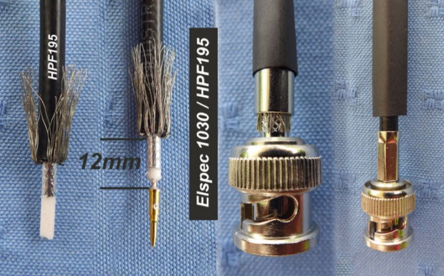 How to install a BNC connector on a coaxial cable like the ELSPEC1030AF / HPF195RG and 58C/U cables
 -
 Choking balun for lower HF and MF bands. (1.8MHz - 10MHz). Requiring a choking balun to isolate the potential RF pick up on the coax cable as it runs past equipment such as computer within the radio room at lower HF and MF frequencies a simple method of winding RG58 coax onto a Powdered Iron Toroid Core was constructed.
 -
 Operating an amateur radio station effectively requires reliable coaxial cable to minimize signal loss between the transceiver and antenna. SIVA Cavi, an Italian manufacturer, produces a range of coaxial cables, including specific 50 Ohm low-loss types suitable for amateur radio applications. Their product line features cables like **RG 58 SHF1**, **RG 213 SHF1**, and **RF 400 SHF1**, which are commonly deployed in HF and VHF/UHF setups. The company also offers specialized cables such as the **HF 214 UF Ultraflex**, a high-performance broadband low-loss 50 Ohm cable designed for flexibility and reduced attenuation across various amateur bands. These cables are engineered with solid or foam dielectric materials, impacting their electrical characteristics and suitability for different power levels and frequency ranges. For instance, foam dielectric cables often exhibit lower loss at higher frequencies, a critical factor for VHF/UHF operations. Beyond amateur radio, SIVA Cavi manufactures cables for digital video broadcast, offshore marine use, and fire detecting systems, demonstrating a broad engineering capability in coaxial cable technology.
 -
 This article describes the construction of a simple dual-band VHF/UHF end-fed vertical dipole antenna designed for local repeater access using an Icom IC-705 radio. Built from a single piece of RG58U coaxial cable, the antenna consists of a 460mm exposed inner conductor, 450mm of intact coax, and a 9-turn choke balun wound on a 27mm former. Mounted on a 10m Spiderpole, the antenna achieves excellent SWR readings (<1.2:1 on 2m, <1.5:1 on 70cm) and provides effective coverage of local repeaters with unexpected reach into distant locations.
 -
 This project details the construction of a compact, circularly polarized Quadrifilar Helix Antenna (QHA) designed for 146 MHz operation. The antenna features a 1/2λ1/2λ helical design with a 2.6:1 aspect ratio, providing 4.5 dB gain and a spheroid radiation pattern. It is ground plane independent and compatible with both vertical and horizontal polarizations, making it ideal for terrestrial and space communications. The design includes step-by-step instructions for building the antenna using readily available materials like aluminum rods, PVC pipes, and RG-58 coaxial cable. The antenna's performance has been validated through comparisons with commercial omnidirectional antennas, showing superior results.
 -
 Presents a detailed construction guide for a 9 dB, 70cm collinear antenna, utilizing readily available _RG58/U_ coaxial cable and PVC pipe for housing. The resource outlines the critical calculations for ½ wavelength sections at 444 MHz, incorporating the coaxial cable's velocity factor of 0.66, which yields a section length of 223 millimeters. It specifies the preparation and soldering of eight such half-wavelength sections, each cut to 231mm to allow for trimming, forming the core of the array. Further instructions detail the integration of a ¼ wave element (169mm #16 solid wire) at the top and a ¼ wave aluminum tube (160mm, 5/16 inch) at the bottom, crimped to the feed point's braid. The guide also addresses RF common mode current suppression by suggesting the use of _FT50-43_ toroids on the feedline. Final assembly steps cover mounting the antenna within ¾" PVC pipe using a wooden dowel, waterproofing connections, and initial SWR checks. The article also discusses scaling the design for different element counts and other VHF/UHF bands.
 -
 The Dipole Bazooka Antenna for 40 meters is a popular choice among amateur radio operators. Its design allows for easy construction using materials like RG58 coaxial cable and PVC. Measurements are calculated using specific formulas; for instance, at a frequency of 7,100 MHz, the total length is approximately 19.74 meters. This antenna offers a performance range of 97% to 99%, with an impedance of 49 to 52 ohms. Additionally, it can handle up to 1 kW of power and requires no modifications for connection.
 -
 Demonstrates the construction of an **ATU-100 (N7DDC)** automatic antenna tuner, detailing the assembly process from component arrival to final enclosure. The resource covers winding the tandem match transformer, connecting the OLED display, and integrating optional control buttons. Specific attention is given to modifying the EEPROM settings for **QRP operation**, reducing the minimum tuning power to 1 Watt, and addressing potential RF interference with CPU by adding capacitors to button connections. The build log includes practical tips such as adapting RG58 coaxial cable strands for PCB mounting and utilizing a repurposed Macbook Pro cover for the custom enclosure. The author references external GitHub pages for comprehensive information, R0AEK's resources for additional details, and a video by MW0SAW for EEPROM configuration across different ATU-100 variants. Future plans involve field testing the completed tuner during SOTA or other portable activations.
 -
 Learn how an experienced ham radio operator rebuilt his trap dipole antenna for 30, 40, and 80 meters after a storm damage. Discover the process of upgrading to a short trap dipole for 40, 80, and 160 meters using double-wound traps made from RG-58 coax. Follow along for construction details and tips on building this unique classi.
 -
 The 4m Slim Jim antenna project provides a construction guide for a low-cost, high-performance aerial designed specifically for the 70 MHz FM band. This design achieves a 1:1 SWR across the 4m FM band with straightforward adjustment of the feed point, utilizing RG-58 coax. Its low angle of radiation contributes to effective signal propagation. Construction involves using plastic knitting needles as spreaders and a telescopic fishing pole for support, with components secured using two-part epoxy. Annealed bare single-core copper wire forms the radiating element. The setup process includes raising the antenna at least 3 meters above ground for tuning, adjusting the RG-58 feed point for optimal SWR, and then soldering connections. Waterproofing is achieved with yacht varnish. The design emphasizes low wind resistance for durability, making it suitable for exposed outdoor installations. A PDF construction diagram is available to supplement the written instructions.