Search results
Query: transmit filter
Links: 48 | Categories: 1
Categories
-
 Circuits of SSB Transceiver, AM DSB Transmitter, Antennas, BFO, VFO, 807, FM Mike, Crystal filter and more.
 -
 Monitoring shortwave broadcast stations effectively requires accurate schedule information to identify transmissions. This online utility offers a straightforward, graphical interface designed to search for and display current shortwave radio broadcasting schedules. Users can precisely filter results by frequency, specific language, broadcaster, time of day, and even by shortwave band, which simplifies the process of pinpointing desired content. The database, last updated on March 26, 2023, details station callsigns (e.g., BBC), start and end times in UTC, days of the week, broadcast language, transmitter power in kilowatts, and azimuth. Crucially, it includes the precise geographical coordinates of transmitter sites, such as Woofferton in the UK or Al Seela in Oman. This data is invaluable for predicting signal paths and optimizing antenna direction for improved reception, a key consideration for serious SWLs. For instance, a search for BBC English broadcasts at 21:04 GMT quickly reveals multiple active frequencies like 17780 kHz from Woofferton, offering a clear overview of current transmissions. The tool processes queries rapidly, returning results within seconds, demonstrating its efficiency for broadcast listening enthusiasts seeking timely information.
 -
 Do your multiple-transmitter field day or contest efforts suffer from intrastation interference ?
 -
 This antenna is very useful for receiving or scanning purposes, but you can use it for transmitting, too. It is 2,94m long and has a pi-configuration (Collins-Filter) for the matching.
 -
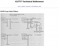 The page provides detailed information on coax stub filters for multi-transmitter setups, including specific lengths for different bands and types of coax. It also references additional technical notes for further analysis.
 -
 Constructing a Lindenblad antenna for 137MHz NOAA satellite reception involves specific design considerations for optimal performance. The resource details the use of 4mm galvanised steel fencing wire, 300-ohm television ribbon cable, and wood/plastic components for the antenna structure. Key dimensions for a 137.58MHz-resonant antenna are provided, derived from the ARRL Satellite Handbook, specifying s, l, w, and d as 42, 926, 893, and 654mm respectively. The antenna is designed for Right Hand Circularly Polarised (RHCP) signals, requiring the four folded dipole elements to be tilted clockwise by 30 degrees. A significant aspect covered is impedance matching between the antenna's 75-ohm impedance and a typical 50-ohm receiver input. A twelfth-wave matching transformer, constructed from 117mm sections of 50-ohm RG-58 and 75-ohm RG-59 coax with a 0.66 velocity factor, is described. The article also addresses coaxial cable and connector selection, recommending 75-ohm Type-N connectors for RG-6 cable in professional setups and F56/F59 connectors for general use, while strongly advising against PL-259/SO-259 connectors for VHF. Strategies for mitigating Radio Frequency Interference (RFI) are discussed, including antenna placement to shield from local TV transmitters and the use of commercial or DIY band-pass filters, such as cavity resonators or helical notch filters, along with ferrite chokes on coaxial cables. Antenna orientation is explored, noting the Lindenblad's 'cone of silence' directly overhead and its maximized sensitivity towards the horizon. An experimental vertical tilt of 90 degrees is presented as a method to improve overhead reception and reduce interference from strong horizontal signals, particularly relevant in high RFI environments like the Siding Spring Observatory site.
 -
 The RigPix database entry provides a comprehensive technical overview of the Icom IC-746 amateur HF/VHF transceiver, detailing its operational parameters and physical characteristics. It specifies the transmit frequency ranges across 10-160 meters plus WARC bands, 50-54 MHz, and 144-146/148 MHz, alongside receive coverage from 0.03-60 MHz and 108-174 MHz. The resource outlines supported modes including AM, FM, SSB, CW, and RTTY, noting a tuning step resolution down to 1 Hz and a frequency stability of ±5 ppm. Key electrical specifications are presented, such as a 13.8 VDC power supply requirement, current drain figures for RX (1.8-2 A) and TX (Max 20 A), and RF output power ranging from 5-40 W for AM and 5-100 W for FM, SSB (PEP), and CW. The entry details the triple conversion superheterodyne receiver system, listing IF frequencies at 69.01 MHz, 9.01 MHz, and 455 KHz, along with sensitivity ratings for various modes and bands. Transmitter section specifics include modulation systems and spurious emission levels. Additional features like a built-in auto ATU, electronic keyer, simple spectrum scope, DSP, and CI-V computer control are noted. The page also lists related documents, modifications, and an extensive array of optional accessories, including various filters, microphones, and external tuners, providing a complete profile of the IC-746.
 -
 One specific challenge in the KazShack, operating Single Operator Two Radios (SO2R), involved sharing a K9AY receive antenna between two transceivers without direct RF connection or manual feedline swapping. The solution, detailed in this project, adapts the **W3LPL RX bandpass filter** design to split 160m and 80m signals, feeding them to separate radio inputs while maintaining isolation. This approach also addresses the issue of strong broadcast band interference from a nearby 50KW WPTF transmitter on 680kc. The construction utilizes T-50-3 toroids and NP0 ceramic capacitors, built in a "dead bug" style on copper clad board. Each band's filter coils are identical and resonated to the desired frequency using an MFJ-259 antenna analyzer. A single DPDT relay, controlled by a remote toggle switch mounted on an aluminum panel, facilitates quick band switching between radios, simplifying low-band operations. While some signal loss is noted, the expected lower noise levels from the receive antenna are anticipated to compensate, potentially reducing the need for constant volume adjustments during toggling between transmit and receive antennas.
 -
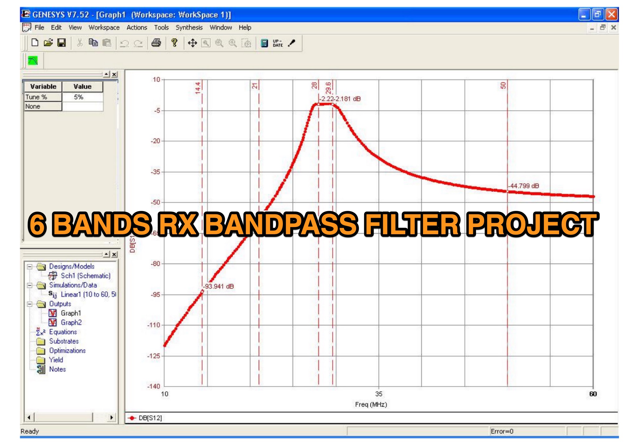 This is a 6 band receive only filter designed to protect your receiver front end and provide 45dB reject at the stop bands. This is a 6-band receive only filter designed to protect your receiver front end and provide 45dB reject at the stop bands. Stop band reject may be limited by the relay isolation. Worse case isolation is at 28 MHz or 35 dB or better. Relay K3/K8 protects the filter during transmit via the PTT line. A 25-50ms delay must be used between transmit and PTT. Do not rely on your radio to provide adequate delay with out using the PTT. You logging software must be set to allow a delay between PTT and time of 1st transmit. This filter will not work with VOX or QSK keying as you will damage the filter.
 -
 The QLF filter is a microprocessor based interface designed to go between a standard Morse code key and a radio transmitter
 -
 This article presents a technical investigation into spurious emissions from the Yaesu FT-847 transceiver when operating on the 70MHz (4-meter) band. The author discovered significant problems with both factory "UK spec" and modified units. Spectrum analysis revealed that when transmitting at 70.2MHz, the radio produces numerous spurious signals, with the most prominent emission at 45.6MHz measuring only 3dB below the fundamental frequency. The study also documents poor power efficiency on 4m (10.3% at 30W output) compared to 6m operation (23.5% at 30W). Tests verified that jumper configurations had no effect on filter selection. The author warns that using these radios on 4m may violate license conditions due to excessive spurious emissions.
 -
 TX RX Systems Inc. offers a robust catalog of RF conditioning products, including **transmitter combiners**, receiver multicouplers, and various RF filters. Their extensive experience, spanning over 45 years in the RF and Land Mobile Radio (LMR) industries, underpins their specialized offerings. They provide solutions for in-building RF coverage, repeater systems, and general RF management, catering to the demanding requirements of professional radio communications. Their product line features **bidirectional amplifiers (BDAs)**, signal boosters, and cavity filters, essential components for optimizing radio system performance. The company emphasizes reliable solutions, leveraging decades of field-proven expertise in designing and manufacturing critical RF infrastructure. From duplexers to cell enhancers, TX RX Systems focuses on delivering high-quality RF components and integrated systems designed to ensure clear and consistent radio signal integrity across diverse operational environments.
 -
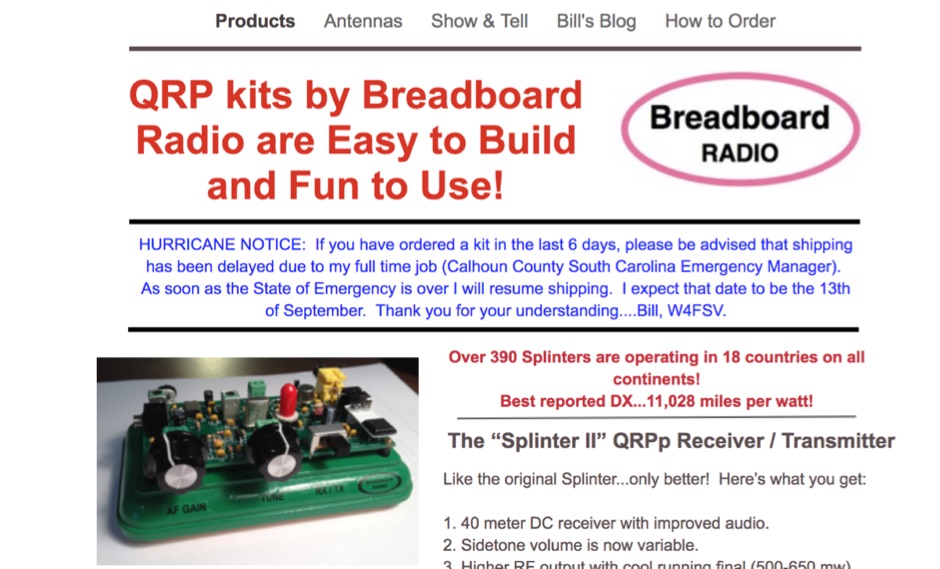 Maker of QRP Kits, QRP CW receiver and transmitters, audio CW Filters, antenna tuners, dummy loads, and morse code practice oscillator
 -
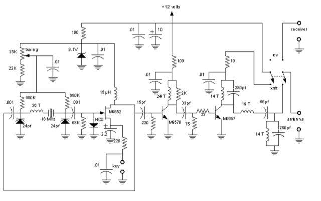
 Presents a QRP AM/CW transmitter project specifically designed for the 10-meter band, utilizing a crystal oscillator and a collector-modulated AM oscillator. The design employs a 2N2219(A) transistor in a Colpitts configuration, generating 100 to 350 mW of RF output power depending on the 9-18 Volt supply voltage and modulation depth. Frequency stability is maintained by a 28 MHz crystal, with fine-tuning possible via a Ct1 trimmer capacitor for approximately 1 kHz adjustment. The resource details the RF oscillator stage, implemented with a 2N2219 NPN transistor, emphasizing frequency stability and low power dissipation. It also covers the amplitude modulation stage, managed by a 2N2905 PNP transistor, which impresses audio information onto the carrier. Selective components (C3, C4, C7, C5) enhance voice frequencies within a +/- 5 kHz bandwidth, and modulation depth is controlled by R2 and R3. The project includes a 3-element L-type narrow bandpass filter (Ct3, L3, C10) to suppress harmonics and ensure a clean output signal. The project provides a complete schematic diagram, a comprehensive parts list including specific capacitor, resistor, and inductor values, and construction notes for the coils (L1, L2, L3). It also offers practical advice on enclosure requirements, suggesting an all-metal case or a PVC box with graphite paint for RF shielding. Operational parameters such as current draw (27mA@9V to 45mA@16V) and input impedance (50 Ohms) are specified, alongside guidance on antenna matching and the importance of a valid amateur radio license for 10-meter band operation.
 -
 Sherwood Engineering Inc. (SEI) offers a repository of technical presentations and white papers focused on optimizing amateur radio transceiver and receiver performance. Content includes detailed analyses of _roofing filters_, transmitted IMD, and receiver characteristics, with specific discussions on products like the Drake R-4C and Icom IC-781. Presentations from events such as Dayton Contest University (2008-2014) cover topics like "How To Optimize Rig Performance," "Transceiver Performance: 10 Years of Change," and "Choosing a Transceiver: Far from Simple." Additional white papers address HF mobile antenna efficiency, ground screen alternatives to buried radial systems, and common receiver problems with solutions. The site also provides historical product information for items like the SE-3 MK IV synchronous AM detector and various 455 kHz mechanical and crystal filters, though many products are no longer in production. Receiver test data and alignment tips for the R-4C are also available, offering insights into rig modifications and performance enhancements.
 -
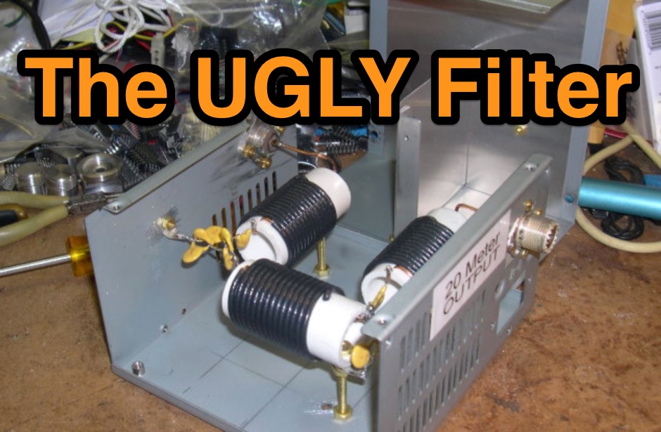 Project to build sets of band pass transmitting filters for reducing the interference between HF transceivers operated in close proximity
 -
 Third-order Cauer filters can boost performance of multi-transmitter, multi-operator contest stations to the next level. The filters are practical and you don’t need expensive test equipment to align them.
 -
 Over 45 years of dedicated work by Robert Sherwood, NC0B, culminated in a wealth of technical insights, particularly concerning **receiver performance** and the intricacies of transceiver design. The site provides access to numerous presentations from events like Dayton Contest University and W4DXCC, covering topics such as optimizing rig performance, the evolution of lab testing, and the impact of roofing filters on transmitted IMD and receiver characteristics. These resources offer detailed analyses and practical advice for serious operators and contesters. While product manufacturing, including the SE-3 MK IV synchronous detector and various Drake R-4C accessories like roofing filters and cooling kits, has ceased, the legacy of technical documentation remains. The site details specific products like the Icom IC-781 and R-9000, and offers insights into 455 kHz mechanical and crystal filters, along with DSP protection strategies. Crucially, the site features extensive receiver test data, allowing radio amateurs to compare the performance of various transceivers. This data, often presented in white papers and slide shows, includes detailed measurements and explanations of key performance metrics, serving as a valuable reference for understanding and selecting high-performance HF gear.
 -
 A 200 kHz bandwidth digital transmission system for image transfer in the Amateur Service is under development, specifically targeting VHF allocations. John B. Stephensen, KD6OZH, leads this project under an FCC Special Temporary Authority (STA) valid until September 10, 2006, authorizing emissions up to 200 kHz bandwidth in the 50.3-50.8 MHz segment. Current regulations typically limit bandwidths to 20 kHz on VHF amateur bands, making this STA crucial for testing wideband digital modes. The modem, a modified **OFDM** (Orthogonal Frequency Division Multiplexed) unit, was initially tested on the 70-cm band. It splits a high-rate data stream into multiple low-rate subcarriers to mitigate multipath echoes. The system uses a DCP-1 card with a Xilinx XC3S400 FPGA and Oki Semiconductor ML67Q5003 microcontroller. The transmitter, located at 36d 46m 30s N, 119d 46m 22s W, generates 150 WPEP into an 8 dBi gain vertical antenna, while the mobile receiver uses a Ham-stick. Three data formats for 50, 100, and 200 kHz channels are being tested, with encoded data rates of 96, 192, and 384 kbps. Verilog code for the VHF OFDM modem is 95% simulated, with modifications from the UHF version including increased filter coefficient precision and a change from Ungerboeck **TCM** to BICM for improved performance over fading paths. Final tests will involve one-way over-the-air measurements of bit error rates and coverage area.
 -
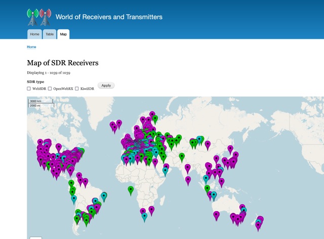 A searchable database of online websdr receivers, lists OpenWebRX, KiWi SDR and WebSDR from all over the world, providing a web interface to search and filter links to websdr
 -
 A synthesized 2.3 GHz Amateur Television (ATV) transmitter design, conceived by Ian G6TVJ, is presented, targeting broadcast-quality video performance on the 13cm band and extending up to 2.6 GHz. The core of the design utilizes a commercial Z-comm Voltage Controlled Oscillator (VCO) that tunes from 2.2-2.7 GHz, providing a +10 dBm output and simplifying RF alignment. This VCO's stability, originally intended for narrowband applications, readily accepts high-frequency video modulation, contributing to the transmitter's robust performance. The exciter stage, incorporating a Mini Circuits VNA 25 MMIC amplifier, boosts the signal to +16dBm, while a Plessey SP4982 prescaler divides the output frequency for the synthesizer. The synthesizer employs a Motorola MC145151 CMOS parallel IC, favored over the common Plessey SP5060 for its superior video modulation characteristics and ease of programming without microprocessors. This choice addresses issues like LF tilt and distorted field syncs often seen with SP5060 designs, particularly when operating through repeaters or over long distances. The MC145151 divides the signal further, enabling precise frequency stepping, with programming handled by EPROMs for channel selection and LED display. The loop filter network, critical for video integrity, was developed through experimentation to prevent the PLL from reacting to video modulation, ensuring a clean transmitted picture. The transmitter incorporates a Down East Microwave commercial power amplifier module, delivering approximately 1.6W output, driven by the exciter through a 3dB attenuator. Construction involves surface-mount SHF components on micro-strip lines etched onto double-sided fiberglass board, housed within a tinplate box. The design boasts no AC coupling in the video path, preserving low-frequency response, a common failing in other ATV transmitters. Performance tests with a 50Hz square wave revealed no LF distortion, and a calibrated "Pulse & Bar" signal showed a near 100% HF response, demonstrating its capability for high-quality ATV transmissions.
 -
 A Short Guide to Harmonic Filters for QRP Transmitter Output. - George Dobbs G3RJV
 -
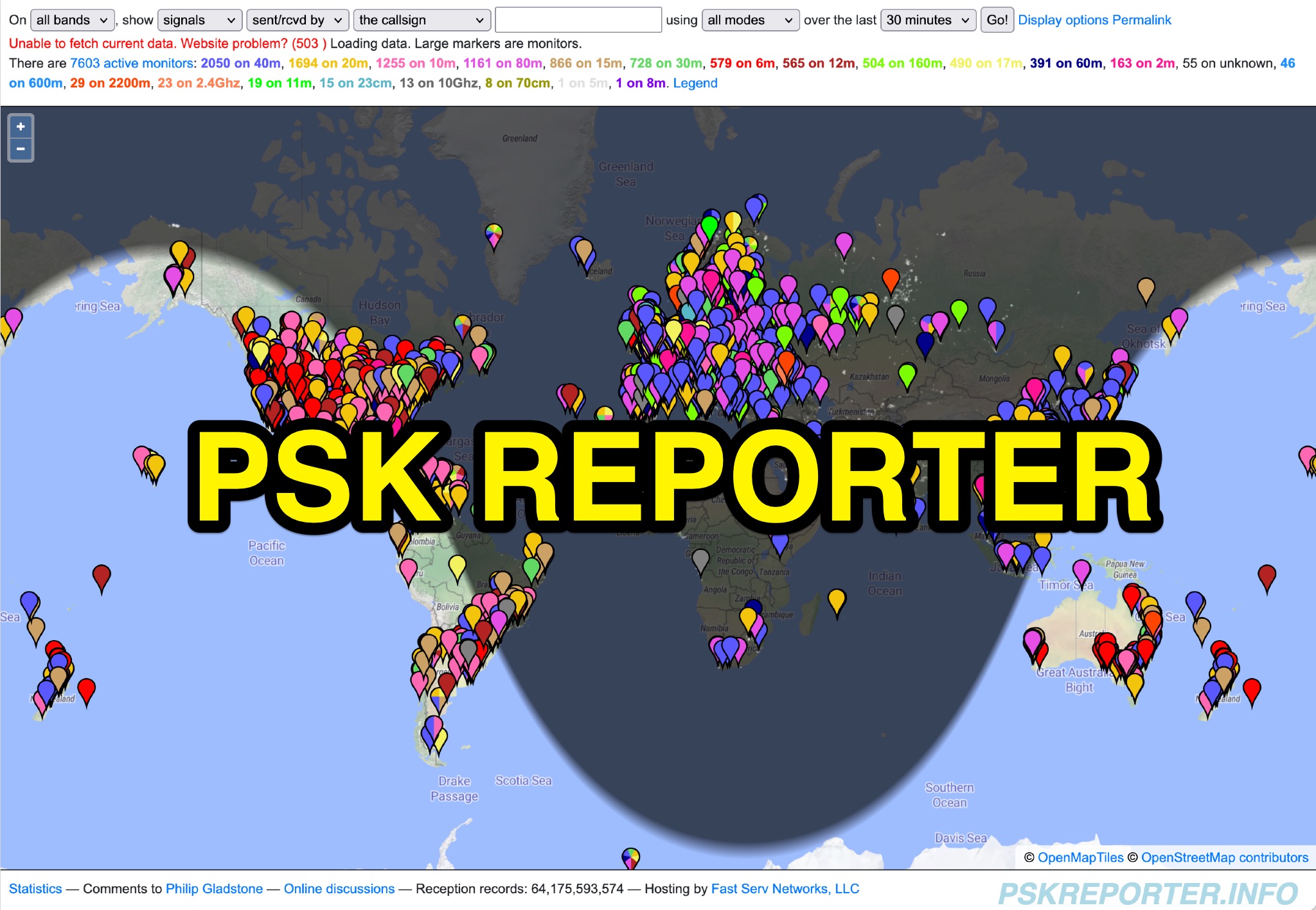 PSK Reporter provides a real-time visualization of amateur radio digital mode reception reports, aggregating data from a global network of monitoring stations. This platform is particularly useful for operators utilizing modes such as FT8, FT4, and PSK, allowing them to observe signal propagation paths and assess their station's reach. The interactive maps display reception reports, enabling hams to analyze band conditions and optimize antenna performance for various frequencies and times of day, aiding in understanding ionospheric conditions. Operators can filter reports by callsign, band, mode, and time, gaining insights into specific propagation events or evaluating the effectiveness of their transmit setup. The data collected helps in predicting optimal operating windows for DX contacts across various digital modes. Philip Gladstone is the contact person for comments and discussions regarding the system.
 -
 The Kenwood TS-870S HF transceiver features two state-of-the-art 24-bit 20 MIPS DSP chips, providing over 100dB out-of-passband attenuation and CW bandwidth adjustable to 50 Hz. It operates across 160-10 meters with 100 watts output, incorporating digital filtering, a beat canceller, and 100 memory channels. The radio also includes a transmit equalizer, RX antenna input, and a K1 Logic Keyer, enhancing signal processing and operational flexibility for amateur radio operators. Advanced capabilities include IF stage DSP, dual noise reduction, and an auto notch filter, all contributing to superior signal reception and clarity. The TS-870S offers a variable AGC, voice equalizer, and an RS-232C port for computer control, with Windows™ software supplied. Its built-in automatic antenna tuner functions on all bands for both transmit and receive modes, streamlining station setup and operation. Available accessories such as the DRU-3A digital recording unit, SO-2 high stability crystal oscillator, and VS-2 voice synthesizer option further extend the transceiver's utility. The unit requires 13.8 VDC at 20.5 Amps and is supplied with an MC-43S hand microphone, making it a comprehensive station component.
 -
 A cavity filter, often a critical component in _duplexer_ designs, functions as a sharply tuned resonant circuit, allowing only specific frequencies to pass while attenuating others. These filters are essential for maintaining signal integrity in environments where multiple transmitters and receivers operate simultaneously on closely spaced frequencies, such as in repeater stations. The article details how these filters, sometimes referred to as _notch filters_, achieve high Q factors, which are crucial for their performance. Understanding the principles of cavity filters is fundamental for any amateur radio operator involved in repeater operation or designing custom RF front-ends. The discussion covers the basic circuitry and operational characteristics that enable these devices to provide significant isolation, often achieving **-80 dB** or more between transmit and receive paths. This level of isolation is vital for preventing receiver desensitization and intermodulation distortion. Properly tuned cavity filters ensure that a repeater can transmit and receive simultaneously on different frequencies without self-interference, a common challenge in VHF/UHF operations.
 -
 Sixty-meter repeaters typically use a 1 MHz frequency separation between input and output, while 2-meter repeaters commonly employ a **600 kHz** split and 70-centimeter repeaters use a **5 MHz** offset. This article details the fundamental technical principles of amateur voice repeaters, explaining how they extend VHF/UHF communication range by receiving on one frequency and simultaneously retransmitting on another. It covers essential components such as receivers, transmitters, filters, and antennas, often situated on elevated locations for optimal coverage. The resource delves into the critical challenge of _desensing_—where the repeater's strong transmit signal overpowers its own receiver—and the engineering solutions employed, including antenna separation and the use of high-Q cavity filters. It also explores various control and timing systems, from basic squelch activation to more sophisticated microcontroller-based boards that manage functions like voice identification, time-out timers, and fault protection. Different access methods are discussed, including open access, toneburst, CTCSS subtone, and DTMF, each offering distinct advantages for managing repeater usage and mitigating interference. Furthermore, the article examines repeater linking, both conventional RF methods and modern internet-based solutions, highlighting how linking expands coverage and promotes activity across multiple repeaters or bands. It introduces less common repeater types such as 'parrot' repeaters, which use a single frequency and digital voice recording, and linear translators, capable of relaying multiple signals and modes simultaneously across different bands, often found in amateur satellites.
 -
 Microprocessor based interface designed receives a signal from a Morse key, processes it, and re-transmits it to the radio. A microprocessor in the circuit is pre-programmed with a proprietary algorithm which makes a number of measurements and adjustments to the less percise human generated code.
 -
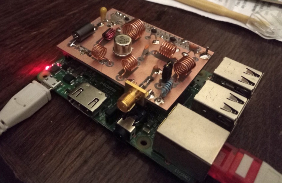 How to limit unwanted harmonics from your raspberry Pi radio transmitter by introducing filters.
 -
 Producers of custom name tags, luggage tags, club badges, Employee Name Tags, Special Event Badges, but also Comtech Amateur Radio Television Transmitters and Receivers D480 filters, Video cameras and accessories.
 -
 Drake TR-7 A.M. Transmit Filter Modification
 -
 A microprocessor based interface designed to go between a standard Morse code key and a radio transmitter. The circuit receives a signal from the key, processes it, and re-transmits it to the radio.
 -
 Thsi article describes a microcontroller driven semi-automatic antenna tuner capable of handling power levels up to 150 watts. The device is a low pass filter tuner manually tuned by setting the optimized L/C combination by hand and then storing the values into the EEPROM of the mictrocontroller to recall them later (seperately for each band from 80 to 10 meters including WARC bands)
 -
 rpitx is a general radio frequency transmitter for Raspberry Pi which doesn't require any other hardware unless filter to avoid intererence. It can handle frequencies from 5 KHz up to 1500 MHz.
 -
 This article introduces an Arduino-based QRP CW Transceiver designed for lower HF bands. The journey begins with the Wotduino, evolving from a keyer to a multi-mode beacon. The development includes a QRP transmitter and culminates in a receiver inspired by Roy Lewallen design. The transceiver, controlled through a control bus features a signal path, modulation, filtering, and adjustable frequency settings. Despite initial testing intentions, successful QSOs on 80 and 40 meters showcase its functional capabilities.
 -
 Home made 40 meter transceiver project. The receiver is a Progressive Receiver with a few modifications. The Transmitter is a modified MFJ Cub circuit. Includes schematic and circuit diagrams for Receive Input Filter, 3-Pole 500 Hz Cohn Filter and 7 MHz Double Tuned Bandpass Filter
 -
 This document details the construction, programming, and operation of a modular WSPR transmitter. The transmitter utilizes an ESP8266 NodeMCU, an SI5351 synthesizer with a TCXO for stability, and selectable low pass filters. Construction involves soldering headers, components, and assembling filter module. The ESP8266 is programmed via the Arduino IDE, requiring library installations and code modifications, including network credentials, callsign, and frequency . The transmitter is powered by USB or Vin terminals and its frequency is selected by jumpers and software settings. The document also covers FCC restrictions and how to use the WSPR network
 -
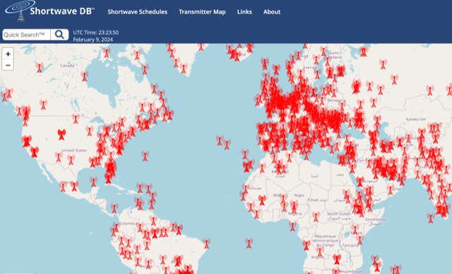 Worldwide Map of shortwave transmitters. Based on shortwave schedule database, this website let you serarch using filters for broadcasts schedule and at the same time to diplay the transmitter map.
 -
 1-watt 17-meter cw transmitter that was originally done about 10 years ago as a club project for RAMS, the Radio Amateur Megacycle Society. It uses a VXO, rather novel at the time. It also uses a bandpass filter at the output rather than the usual lowpass
 -
 A homebrew spectrum analyzer, the Specan, provides a crucial measurement capability often missing from the typical amateur radio shack, allowing for detailed analysis of RF signals up to 70 MHz. This double-conversion superheterodyne receiver design incorporates 112 MHz and 12 MHz intermediate frequencies, utilizing an _Si570_ as the local oscillator for fine tuning down to 1 Hz steps. It offers two resolution bandwidths: 300 KHz for broad spectrum sweeps and 1 KHz for precise close-in distortion measurements, achieving an 80 dB spur-free dynamic range at 1 KHz resolution. The project, a reboot of the classic _W7ZOI/K7TAU_ design from November 1998 QST, integrates an _Arduino_ microcontroller for controlling the Si570, managing a front-panel LCD, and communicating with a PC for spectrum plotting. This approach significantly reduces cost compared to commercial units, making advanced RF diagnostics accessible to homebrewers. The Specan can measure carrier suppression, VFO cleanliness, antenna VSWR, transmitter harmonics, and filter passband shapes, providing insights beyond what an oscilloscope or frequency counter can offer. Construction emphasizes modularity and careful shielding, with each stage built and tested individually on unetched copper clad board. The design includes detailed instructions for integrating the Arduino, building the Si570 oscillator, and aligning the various modules, often using the Specan itself for calibration. It requires a well-regulated linear power supply and can be built with common tools and readily available components, making it a practical and rewarding endeavor for those looking to enhance their RF test bench.
 -
 This article details the design and construction of a compact 20-meter QRP SSB transceiver by Pete Juliano, N6QW, measuring just 2 x 4 x 2 inches—small enough for a shirt pocket. Inspired by a 1963 QST design and refined from a prior version, it employs bilateral circuits, a 4.9152 MHz homebrew crystal filter, switched-crystal VXO for 60 kHz coverage (14.160-14.220 MHz), and standard components like ADE-1L mixers and IRF510 PA for 1W output. Key innovations include a double-sided PCB skeletal frame for shielding and isolation, Vectorboard sub-assemblies, and ultra-miniature relays. The bilateral receiver/transmitter shares stages, omitting AGC for simplicity, while a W3NQN LPF and optional 10W external amp enable DX contacts. Tune-up focuses on crystal matching and bias for linearity. Videos on YouTube demonstrate performance, confirming excellent stability and audio. Total cost nears $100, prioritizing portability over features like CW.
 -
 Effective suppression of harmonics and parasitic radiation from HF transmitters is crucial, especially with the increasing sensitivity of VHF/UHF radio channels to interference. This project details a hybrid low-pass filter (LPF) designed to operate across the HF bands up to 51 MHz, making it suitable for 6-meter band operations while providing deep VHF/UHF suppression. The design addresses the challenge of modern interference landscapes, where even microvolt-level signals can disrupt wireless sensors and other simple VHF/UHF receivers. The filter utilizes a single elliptic link, combining high cutoff steepness with robust suppression in the hundreds of megahertz range. A key feature is the use of only two standard capacitor values, simplifying construction and component sourcing. The article provides a detailed schematic, performance characteristics, and _RFSim99_ model file, demonstrating a reflection coefficient S11 below 0.017 (VSWR < 1.03) across 1-51 MHz, ensuring minimal degradation to the antenna system. Construction notes include coil winding specifications and capacitor selection guidance, with recommendations for _FR-4_ assembly. Two capacitor sets are presented, with the first variant recommended for its lower RF current demands, keeping currents below 3 A at 1 kW passing power at 51 MHz. Fine-tuning involves adjusting frameless coils, with considerations for capacitor tolerance and high-frequency capacitance measurement accuracy.
 -
 Learn how to enhance your 160 meter reception by building and using a custom band pass filter. Discover how this filter can reduce interference from strong AM broadcast signals, improving the overall performance of your receiver. Find out about the challenges of creating a filter that balances signal loss and attenuation at specific frequencies, and how it can benefit hams operating near powerful transmitters. Whether you're experiencing IMD issues or looking to optimize your 160 meter setup, this article provides practical insights and solutions for ham radio operators.
 -
 A dual insert microphone design for the Icom IC-7300 transceiver utilizes a **Besson BZ2400 M4 Rocking Armature** insert for frequencies from 500 Hz to 3 kHz, exhibiting a rising response of approximately 11 dB. A generic Electret Condenser insert, powered by the transceiver's microphone line, covers the low-frequency range from 100 Hz to 500 Hz. A Low Pass Filter is incorporated after the Electret insert to prevent frequency overlap, and a pre-set potentiometer (VR1) adjusts the low-frequency response, balancing the output of both inserts. The design emphasizes a "Close Talking" arrangement and addresses audio "colorization" by housing the Besson insert in a thick rubber holder with a foam boot, separate from the circuitry, with the Electret insert also wrapped in a foam boot. Critical importance is placed on using the correct BZ2400 M4 insert with 12 holes in its face plate. The frequency response table for the BZ2400 M4 insert shows 0 dB at 500 Hz, rising to +11 dB at 3000 Hz, while the Electret insert with the Low Pass Filter provides 0 dB at 100 Hz, rolling off to -9 dB at 500 Hz and -50 dB at 3000 Hz. This combination ensures a broad, balanced audio spectrum for SSB operation. The project includes a circuit diagram, a comprehensive parts list detailing components like a 1 Henry iron-cored inductor (L1) and various capacitors, and a board layout within the metal tube. The completed unit provides a tailored audio profile for the IC-7300, enhancing transmit audio quality.
 -
 The project details the construction of a GM3OXX OXO transmitter, designed to accommodate **FT-243 crystals** using 3D-printed FX-243 holders from John KC9ON. It presents specific frequency adjustments, noting a 7030 KHz HC-49/s crystal could be tuned from 7029.8 KHz to 7031.7 KHz with an internal 45pF trimmer capacitor. The build incorporates a modified keying circuit to prevent oscillator run-on key-up and includes a TX/RX switch for sidetone via a connected receiver, with the transmitter output routed to a dummy load on receive. Practical construction aspects are thoroughly covered, including the process of cutting a rectangular opening in a diecast enclosure for the FT-243 socket and the selection of a **low-pass filter** (LPF) based on the QRP Labs kit, derived from the W3NQN design. The author achieved approximately 800mW output power from a 14.75V supply, measured with an NM0S QRPoMeter, using a 16.5-ohm emitter resistor in the 2N3866 final stage. The article also touches upon the potential for frequency agility across the 40M band using multiple FX-243 units with various crystals. The narrative includes a brief diversion into Bob W3BBO's recent homebrew projects, such as his Ugly Weekender MK II transceiver, highlighting the enduring appeal of classic QRP designs. The author reflects on the personal satisfaction derived from building RF-generating equipment, irrespective of DX achievements, and shares experiences of making local contacts with the 800mW OXO transmitter on 40 meters.
 -
 The article discusses the construction of a UHF band-stop stub filter to protect an APRS receiver from potential damage during a balloon launch. The author, who communicates using a 441 MHz transmitter, needed to ensure that the RTL-SDR dongle receiving at 144 MHz wouldn't be damaged by the transmissions. The solution involved creating a quarter-wavelength open stub filter using coaxial cable, which attenuates the 441 MHz signal while allowing the 144 MHz signal to pass through. The filter's design is based on the principles of constructive and destructive interference, with careful measurement and trimming to achieve the desired frequency response. The final filter provided 34.8 dB of insertion loss at 441 MHz and minimal loss at 144 MHz, effectively protecting the receiver.
 -
 SAT filters ensure effective full-duplex satellite QSOs by mitigating interference between 145 MHz uplink and 435 MHz downlink signals. Custom coaxial and SMD-based filters address transmitter harmonic interference and improve receiver isolation, achieving over 70 dB suppression in the undesired band. Designed for simplicity, these filters maintain optimal VSWR and are housed in shielded brass enclosures. Practical implementations with Yagi antennas demonstrate compatibility with SDR systems, enabling seamless communication even in challenging satellite conditions, such as low-elevation passes and DX pile-ups.
 -
 The aprs.fi Android application offers immediate, real-time access to APRS position information, weather reports, and telemetry graphs, allowing users to zoom and browse stations globally without delay. It includes features like callsign and address search with history, multi-station tracking, and map filtering for elements such as weather stations and AIS targets. The app also supports KML and GeoJSON overlay files for enhanced map visualization. Users can beacon their position directly to aprs.fi or connect wirelessly to a Bluetooth, BLE, WiFi, or USB-attached TNC for receiving and transmitting position beacons without an internet connection. The application runs on the robust and fast aprs.fi database, providing _Dark Mode_ support for improved ergonomics in low-light conditions and high-resolution graphics for modern displays, including the full APRS symbol set. While the core application is a one-time purchase, some advanced functionalities, such as APRS text messaging, a high-performance software DSP modem, and _APRS-IS_ beaconing with up to **10 callsign profiles**, require an additional "Extra Features" subscription. This subscription also unlocks RX iGate functionality and extended time ranges for map and graph views, expanding its utility for serious APRS operators.
 -
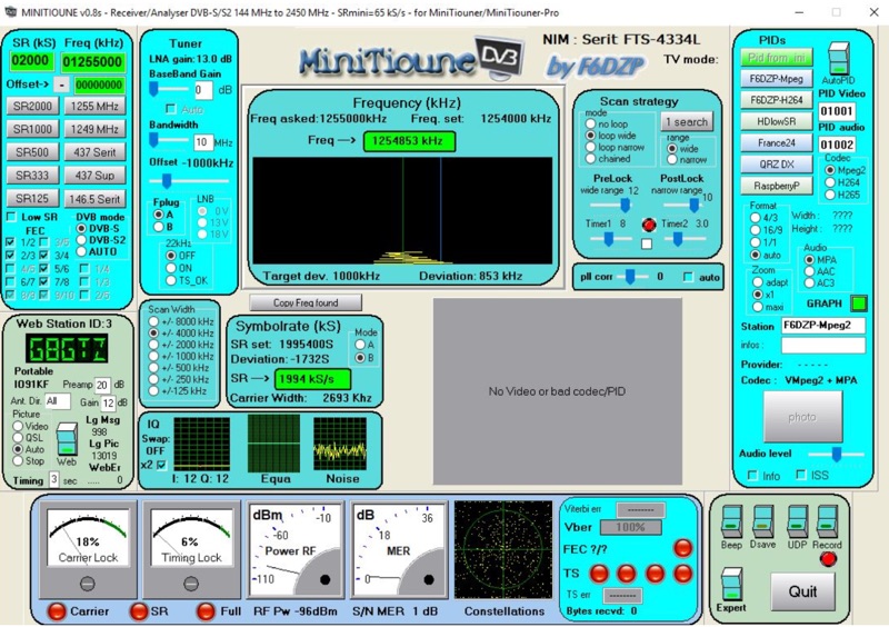 Receiving Digital Amateur Television (DATV) signals requires specialized software to interface with hardware tuners and decode the video stream. The _MiniTioune_ software, developed by F6DZP, serves this purpose, providing a Windows-based application for DVB-S and DVB-S2 reception and analysis. It is designed to work in conjunction with _MiniTiouner_ hardware, enabling hams to monitor DATV transmissions, including those from the QO-100 geostationary satellite. The resource outlines the initial setup process, including connecting the MiniTiouner hardware via a high-quality USB2 mini cable and running diagnostic test software. It details how to configure essential parameters such as symbol rate (SR), FEC rate, and DVB mode for various signal sources, from domestic satellite dishes to local DATV transmitters. Troubleshooting steps for common issues like "no video displayed" are also provided, often pointing to corrupted software filters or incorrect _Auto PID_ settings. Advanced features like the Web monitor for remote signal reporting and integration with _VLC_ media player for more tolerant decoding of non-DVB compliant signals are covered. The document also references a comprehensive user guide by W6HHC for the _MiniTiouner-Express_ system, which utilizes the same software, offering further in-depth assistance for operators.