Search results
Query: tuning coil
Links: 29 | Categories: 0
-
 Build your mobile antenna which outperforms Hustler by 10db and ATAS-100 by 18db. From 80 to 10m. The HB9ABX mobile HF antenna, designed for 10 to 80 meters, was developed by Felix Meyer and outperforms commercial antennas like HUSTLER and YAESU ATAS-100/120 in field tests. Made from fiberglass rods and enamelled copper wire, it includes a loading coil with adjustable taps for tuning across bands. Installation requires solid grounding, and adjustments are made via whip length and coil settings. An antenna tuner ensures optimal SWR. Users must handle fiberglass with care due to health risks. This design proved highly effective in South America and Europe.
 -
 The Flower Pot Antenna project details a portable dual-band antenna primarily operating on 10 meters, with secondary resonance near the 30-meter band. Construction involves winding RG58 coaxial cable uniformly around a large plastic flower pot, approximately 70cm high with a 60cm top diameter. The design eliminates the need for radials, contributing to its compact and lightweight nature. Key construction steps include soldering the inner conductor to the shield at one end of the wound cable and connecting the wound cable's shield to the rig cable's inner conductor at the base. An LC network, comprising a variable capacitor (0-200pF) and an inductor (10 coils, 5cm diameter, 2mm wire), is inserted between the wound cable's inner conductor and the rig cable's shield. Tuning is performed with an antenna analyzer, adjusting cable length and the variable capacitor for optimal impedance on 10 meters. The antenna performs effectively when installed horizontally.
 -
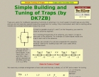 A new and simple method for tuning traps. You need 2-3Watt of your TRX and two homemade coupling coils by DK7ZB
 -
 W5ALT Indoor Vertical Antenna is a base loaded vertical antenna that can be tuned on almost all HF bands by adjusting a big coil. Operating a ham radio station from an apartment in Maracaibo, Venezuela, the author demonstrates effective communication with over 100 countries using a custom-built indoor vertical antenna. Addressing common misconceptions, the design uses a balanced approach with radials and a base-loaded vertical element made from affordable materials. The antenna fits discreetly indoors, covers 6 to 40 meter bands, and achieves acceptable SWR with an MFJ tuner. Despite limited space and typical apartment challenges, the setup enables reliable DX contacts, confirmed by numerous QSL cards, proving indoor antennas can perform well in constrained environments.
 -
 The Screwdriver Antenna Memory (SAM) product is designed to enhance the mobile antenna commonly called the "Screw Driver". It replaces your current control unit and provides an automated memory feature that eliminates the visual coil tuning method commonly used.
 -
 Presents the design and construction of the OK2FJ Bigatas, a portable, automatically tuned vertical antenna covering 80 through 10 meters. It details two distinct control systems: one utilizing BCD band data from Yaesu FT-857/897 transceivers, and another employing voltage level sensing for the Yaesu FT-817. The resource provides specific instructions for building the antenna's radiating element, loading coil with switchable taps, and the control circuitry, emphasizing the use of readily available components. The article outlines the physical construction of the antenna, including the use of duralumin tubes for the radiator and a PVC tube for the coil form. It specifies coil winding details, tap points, and the integration of radial wires for ground plane operation. The control electronics section provides schematics and component lists for both the BCD decoder (using a 74LS42 IC) and the voltage comparator (using an _LM3914_ bargraph driver), enabling rapid, automatic band switching without the minute-long tuning delays common in other systems. Crucially, the antenna achieves rapid band changes, with typical SWR values centered on common operating segments, such as **3.7 MHz** for 80m SSB. It also discusses modifications for CW operation on 80m and the trade-offs between antenna efficiency and full-range automatic tuning on higher HF bands, where manual adjustment of radiator length is suggested for optimal performance on 15m, 12m, and 10m. The resource includes construction photos and a discussion of cable requirements for reliable operation.
 -
 Operating a ZS6BKW antenna often involves understanding its lineage from the _G5RV_ design, with specific modifications by ZS6BKW to optimize performance on several bands. Through computational analysis and field measurements, the antenna's dimensions were refined to allow operation on 10, 12, 17, 20, and 40 meters without an antenna tuner. For 80, 30, and 15 meters, a tuner is necessary, though efficiency on 30 and 15 meters is noted as not particularly high. The physical configuration consists of two 13.755-meter radiating elements fed by a 12.20-meter section of 450-ohm ladder line. Tuning the antenna on the 20-meter band is critical, and any deviation in the ladder line's characteristic impedance necessitates recalculating the element lengths. The design is also referenced in the 12th edition of _Rothammel's Antennenbuch_, page 219. Proper common mode current suppression is crucial at the transition from ladder line to coaxial cable. This can be achieved with a common mode choke, such as several turns of coax wound into a coil or over a ferrite toroid like an Amidon T130. While a 1:1 balun is an option, it may introduce issues.
 -
 Presents a construction project for a linear-loaded 40-meter rotatable dipole, detailing the design evolution from mid-element coils to 300-ohm twinlead loading. It covers material selection, including repurposed fishing poles and EMT conduit, and outlines the assembly process for the antenna elements and mounting plate. The resource provides specific measurements for element lengths and linear loading sections, along with SWR plots demonstrating the antenna's resonance at 7.035 MHz with a 1.1:1 SWR, and bandwidth up to 7.120 MHz below 2:1 SWR. The article documents the antenna's performance during various RTTY and CW contests, including the SARTG RTTY and SCC RTTY contests in August 2006, and the ARRL DX CW and CQWW WPX RTTY contests in February 2007. It reports successful operation at 500-1000W, noting improved performance after replacing a faulty coax cable. Specific DX contacts from British Columbia, including stations in Europe and South Africa, are listed, illustrating the antenna's capability despite its shortened length and relatively low height of 55 feet. The content highlights practical considerations such as weatherproofing the connections and supporting the fiberglass elements to prevent sagging. It also includes a brief comparison to an inverted-V at similar height and a ground-mounted vertical, noting the rotatable dipole's quieter reception. The author shares insights into the iterative design process and tuning adjustments made to achieve optimal resonance.
 -
 GW4ALG's _136 kHz Pages_ document the evolution of vertical antennas for the 2200m band, starting with a prototype mounted on a house wall. This initial design, despite achieving the first **395 km** GM-GW QSO, suffered from significant insulation breakdown, high RF losses due to proximity to the house, and difficult tuning adjustments. The author details the challenges of maintaining resonance and matching with a variometer in the loft, noting that adding three earth spikes offered no measurable improvement over a simple water tap connection. The subsequent experimental 12m vertical, relocated away from the house, significantly reduced dielectric losses and proved far more effective. This antenna enabled GW4ALG to set a world DX record on 136 kHz with a **1916 km** QSO to OH1TN, and an intra-UK record of **703 km** to GM3YXM/P. The resource further explores the use of helium-filled balloons to extend the vertical radiator, achieving heights up to 27m, typically 20m, for enhanced low-band performance. Practical advice on balloon types, inflation, and critical insulation between the wire and balloon is provided, emphasizing safety and avoiding arcing.
 -
 Presents a QRP AM/CW transmitter project specifically designed for the 10-meter band, utilizing a crystal oscillator and a collector-modulated AM oscillator. The design employs a 2N2219(A) transistor in a Colpitts configuration, generating 100 to 350 mW of RF output power depending on the 9-18 Volt supply voltage and modulation depth. Frequency stability is maintained by a 28 MHz crystal, with fine-tuning possible via a Ct1 trimmer capacitor for approximately 1 kHz adjustment. The resource details the RF oscillator stage, implemented with a 2N2219 NPN transistor, emphasizing frequency stability and low power dissipation. It also covers the amplitude modulation stage, managed by a 2N2905 PNP transistor, which impresses audio information onto the carrier. Selective components (C3, C4, C7, C5) enhance voice frequencies within a +/- 5 kHz bandwidth, and modulation depth is controlled by R2 and R3. The project includes a 3-element L-type narrow bandpass filter (Ct3, L3, C10) to suppress harmonics and ensure a clean output signal. The project provides a complete schematic diagram, a comprehensive parts list including specific capacitor, resistor, and inductor values, and construction notes for the coils (L1, L2, L3). It also offers practical advice on enclosure requirements, suggesting an all-metal case or a PVC box with graphite paint for RF shielding. Operational parameters such as current draw (27mA@9V to 45mA@16V) and input impedance (50 Ohms) are specified, alongside guidance on antenna matching and the importance of a valid amateur radio license for 10-meter band operation.
 -
 The resource details the construction of a multiband trap-style Inverted-V antenna designed for operation on 3.5 MHz, 7 MHz, 14 MHz, 21 MHz, and 28 MHz. It presents specific winding data for the traps, including the number of turns, wire gauge, and coil former dimensions, crucial for achieving resonance on the target bands. The document provides a parts list and a diagram illustrating the antenna's physical layout and trap placement. It outlines the process for building the traps using PVC pipe formers and specifies the required capacitor values for each trap. The design emphasizes a practical approach to achieving multiband operation with a single feedline, a common goal for HF operators with limited space. The document includes a table with antenna segment lengths for each band, allowing for precise replication of the design. It also offers insights into tuning and adjustment, ensuring the antenna performs optimally across the designated amateur radio bands.
 -
 The **136kHz Vertical Antenna** at G3YMC employs a Butternut HF2V structure, standing 10m tall. It integrates a 6.5mH loading coil to achieve resonance, with a matching transformer for impedance adjustment. The antenna's configuration includes top loading via a 12m horizontal wire, enhancing capacitive impedance. Initial measurements indicated a high impedance of around 300 ohms, necessitating a transformer for a 50-ohm match. Despite challenges with ground losses, the vertical antenna has shown improved performance in specific directions, filling nulls present in the previous loop antenna setup. The tuning remains broad, with variations due to environmental factors affecting the matching. Ongoing adjustments and comparisons with the loop antenna will continue to refine its effectiveness.
 -
 The NB6Zep Antenna, an electrically shortened 80-meter end-fed wire, addresses space constraints for low-band operation by integrating two loading coils into a 37-foot wire. This design, modeled with _EZNEC_, explores configurations like the quarter-wave sloper and inverted-L, with the latter providing a more vertical radiation pattern and practical backyard deployment. The resource details specific coil construction, recommending 21 uH coils made from _BW coil stock #3026_ or similar, and outlines wire segment lengths for optimal tuning. Performance analysis indicates a radiating efficiency of approximately 27% with good ground conductivity, resulting in a signal typically 3-4 dB down compared to a full-size quarter-wave vertical. The antenna exhibits a narrow bandwidth, around 50 kHz, due to its high Q, necessitating a tuner for broader band operation. Feedpoint impedance is low, with ground resistance playing a critical role in achieving a usable SWR. The article emphasizes the importance of an effective ground rod at the feedpoint for proper operation and tuning, suggesting an antenna analyzer for precise adjustments. It confirms the antenna's suitability for DX, citing successful contacts from Oregon to the East Coast and Hawaii on a 160-meter variant, making it a viable option for urban operators seeking low-angle radiation on 80 meters.
 -
 Constructing a dip oscillator provides radio amateurs with a fundamental piece of test equipment for resonant circuit analysis. This particular design, adapted by VK3YE from a concept by _Drew Diamond VK3XU_, details a practical build using readily available components. The unit incorporates four plug-in coils, covering a frequency range from **2.6 MHz to 55 MHz**, mounted on 5-pin DIN plugs for versatility. A salvaged two-gang air dielectric variable capacitor, fitted with a vernier reduction drive, serves as the tuning mechanism, with the smaller gang optimizing bandspread at higher frequencies. In practical application, the dip oscillator is used by setting the meter needle to approximately two-thirds scale. When the instrument's coil is brought near a tuned circuit under test, a noticeable dip in the meter reading indicates resonance. This allows for precise measurement of resonant frequencies in antennas, filters, and other RF circuitry, proving invaluable for homebrewing and troubleshooting. The design emphasizes short wire runs for stable operation, particularly at the higher end of its operational range.
 -
 Isotron antennas are antennas of reduced size, without tuning. On 40 and 80m band, it is made of two plates into v whose angles are connected by a coil. In this article the description of a home made realization for the 40m band.
 -
 Constructing an End-Fed Half-Wave (EFHW) antenna offers a practical solution for HF operators seeking a multiband wire antenna without the need for extensive radial systems. This design typically employs a high-impedance transformer at the feed point, matching the antenna's inherent high impedance to a 50-ohm coaxial feedline. The article specifically details a 2012 approach, focusing on a transformer with a 49:1 turns ratio, which is a common configuration for EFHW antennas. The resource outlines the construction of a wire element cut for a half-wavelength on the lowest desired band, with specific coil arrangements enabling operation on harmonically related bands such as 40m, 20m, and 10m. It discusses the physical dimensions and winding details for the matching transformer, often utilizing a ferrite toroid core to achieve the necessary impedance transformation. The content provides insights into the operational principles and practical considerations for deploying such an antenna, including methods for tuning and optimizing performance across multiple amateur radio bands. While acknowledging that the presented information from 2012 may be superseded by newer insights, it serves as a foundational reference for understanding EFHW antenna theory and construction.
 -
 The _G3TSO_ Mobile Antenna Page details construction and tuning methods for mobile antennas operating across **10 to 160 metres**. The content describes a Hustler-based design, optimized for RF performance and vehicle speeds, featuring centre loading. For optimal operation on various bands, the loading coil placement requires clearance from the vehicle body. Antenna resonance is critical for efficient mobile operation. A mobile antenna's base impedance may be as low as 27 ohms, requiring specific matching to achieve maximum radiation, as a minimum SWR at the transmitter does not always indicate resonance or maximum output. Tuning involves physical adjustment of antenna length to achieve resonance at the operating frequency. The _G3TSO_ page outlines a tuning procedure utilizing a low-power signal source and a field strength meter to identify maximum radiation before impedance matching. Loading coil placement, either at the base, center, or top of the antenna, influences radiation efficiency and mechanical stability for mobile installations. Centre-loaded whips, such as the Hustler design, offer a compromise between efficiency and stability, often for single-band operation. Helically wound antennas, including those for **28 MHz**, may present base impedances around 17 ohms, resulting in a 3:1 SWR at resonance. Low resistance grounding at the antenna base is also specified for optimizing performance and minimizing RFI during mobile operation. DXZone Focus: Mobile | Any | Antenna Tuning | HF
 -
 This article describes the construction of a three-band vertical antenna for the WARC bands (10, 18, and 24.9 MHz). Unlike a previous design using thin wire requiring a complex matching device, this version uses a telescopic set of pipes, reducing reactances and simplifying the matching device to two coils and two capacitors. The article provides details on the antenna model, the matching device circuit, and tuning methods, including the use of frameless coils and variable capacitors. With proper tuning, the antenna achieves a VSWR not exceeding 1.3 across all bands, demonstrating a practical and efficient design for amateur radio enthusiasts.
 -
 Integrating a **160-meter vertical wire antenna** with an existing 80-meter Yagi system presents unique challenges for Top Band operation. This project outlines the author's experiences with seasonal antenna removal and reinstallation, a necessary task for agricultural land use. It details specific issues encountered, such as incorrect coil sizing and relay configuration problems, providing practical insights into common pitfalls. The article describes the iterative tuning process, comparing **NEC model** predictions with actual on-air performance. It emphasizes the importance of precise measurements and adjustments to achieve optimal resonance and impedance matching. The author shares lessons learned from troubleshooting, including the impact of ground system integrity and feedline considerations. Concluding with an antenna checkup, the resource addresses long-term maintenance aspects, including galvanic corrosion prevention and general upkeep for reliable operation.
 -
 This PDF article introduces a series of dual-tuned bandpass filters designed for input tuning in amateur band receivers. Developed by Stefen Niewiadomski, these filters feature 50-ohm input/output impedance and can be cascaded for improved roll-off outside the passband. The designs use readily available TOKO coils, with taps on the tuned winding for matching input circuits with impedances around 1k ohm. The inductors are core-tuned, with average inductance values provided for easier matching to other inductors.
 -
 Being frequently away from home, the author owner of an Elecraft KX3 missed the opportunity to work /M. They devised a portable antenna solution, incorporating a coil and car body, enabling multi-band tuning. Despite its unconventional design, the antenna exhibits promising performance, resembling a vertical dipole.
 -
 A vertical antenna project for POTA operations. This shortened antenna is aimed to work from 20 to 40 meter band implementing a loading coil, with an additional wire lenght, determined by on field testing and tuning.
 -
 For amateur radio operators engaging in portable operations like SOTA or POTA, rapid deployment of an effective antenna system is paramount. This video resource details the assembly process for the Buddipole multiband dipole antenna, showcasing its components and how they fit together. Rob, VK5SW, systematically presents the mast, coil arms, radiating elements, and the VersaTee hub, emphasizing the modular design that allows for quick configuration changes across various HF bands. The demonstration highlights the antenna's adaptability for different operating environments, from a ground-mounted vertical to a horizontal dipole. The video illustrates the ease with which the antenna can be packed and deployed, making it a practical choice for activations where setup time is limited. The Buddipole's design facilitates efficient band changes and tuning, crucial for maximizing QSO opportunities during field operations.
 -
 The PA0FRI Unbalanced/Balanced ATU is a home-built antenna tuner designed to efficiently match a W8JK 2-element beam antenna fed with a 450-ohm twin lead. Based on PA0FRI’s S-Match design, it optimizes energy transfer while maintaining balance, reducing losses, and ensuring proper radiation. The tuner uses a roller inductor, air variable capacitors, and a T200 iron powder coil, allowing fine-tuning across 14-50 MHz. Extensive lab tests confirm minimal attenuation and precise impedance matching, making it a reliable and efficient ATU for balanced antennas.
 -
 Learn how to construct a balanced Antenna Tuning Unit (ATU) for your ham radio equipment. Follow the instructions provided by Bengt, SM6APQ, to create a variable capacitor insulated from the ground for additional safety. Discover how to set up the ATU for the 20 to 10m band with proper spacing between coils. Use low power when adjusting the ATU for lowest SWR. Avoid using switches and opt for banana plugs for flexible connections. Visit the Creative Science Centre website for more information and resources on ATU construction.
 -
 The 1/4 wavelength vertical antenna project, initially designed for 20 meters, has evolved into a versatile portable solution covering 10 through 60 meters. K0BXB details its construction, emphasizing a bottom-loaded design with a tapped loading coil and four 10-foot counterpoise wires. The author shares personal experiences and field results, including **18 QSOs** during a park activation on 17m and 30m with 10 watts, and a **2,435-mile** contact with a contest station in Bonaire on 20m using 5 watts. Comparisons are drawn to commercial offerings like the _Wolf River Coils TIA_ and _QRPGuys Triband Vertical_, highlighting the DIY antenna's small footprint, light weight, and ease of tuning for POTA activations. The resource includes insights into using test equipment such as the _NanoVNA_ for SWR optimization and discusses various radiator lengths, from 17-foot wire to a 102-inch whip, demonstrating adaptability for different portable setups. Construction tips cover coil winding, tap placement, and connecting feedlines and radials using common components.
 -
 Effective suppression of harmonics and parasitic radiation from HF transmitters is crucial, especially with the increasing sensitivity of VHF/UHF radio channels to interference. This project details a hybrid low-pass filter (LPF) designed to operate across the HF bands up to 51 MHz, making it suitable for 6-meter band operations while providing deep VHF/UHF suppression. The design addresses the challenge of modern interference landscapes, where even microvolt-level signals can disrupt wireless sensors and other simple VHF/UHF receivers. The filter utilizes a single elliptic link, combining high cutoff steepness with robust suppression in the hundreds of megahertz range. A key feature is the use of only two standard capacitor values, simplifying construction and component sourcing. The article provides a detailed schematic, performance characteristics, and _RFSim99_ model file, demonstrating a reflection coefficient S11 below 0.017 (VSWR < 1.03) across 1-51 MHz, ensuring minimal degradation to the antenna system. Construction notes include coil winding specifications and capacitor selection guidance, with recommendations for _FR-4_ assembly. Two capacitor sets are presented, with the first variant recommended for its lower RF current demands, keeping currents below 3 A at 1 kW passing power at 51 MHz. Fine-tuning involves adjusting frameless coils, with considerations for capacitor tolerance and high-frequency capacitance measurement accuracy.
 -
 The LKJ Wednesday Night Special Antenna, designed by John Whiteman K5LKJ, is a compact 50-foot coil-loaded dipole for 80-meter operation, ideal for space-limited hams in residential areas. Using two 1-inch diameter PVC coils with 87 turns of #16 magnet wire each—placed 10 feet from the center—it tunes to 3.910 MHz for local nets like BVARC Rag Chew. Constructed with #14 wire, ceramic insulators, and Mini-8X feedline, it handles 1000W, performs well at low heights for NVIS, and requires a tuner for bandwidth. Collaborative tuning by club members ensured success.
 -
 This page discusses the construction and design of a shortened 2-element Yagi antenna for the 40-meter band, focusing on the driven element. The author shares insights on adding hats to the coil to reduce losses and improve performance. The article also mentions the use of EZNEC modeling software and an AIM4170 analyzer for tuning. Amateur radio operators interested in such antenna design and optimization for the 40-meter band can find useful information and practical tips on this page.