Search results
Query: two antennas
Links: 111 | Categories: 2
-
 The page describes two types of 2 meter J-Pole antennas, one made of copper pipe and a roll-up J-pole made of TV twin lead, providing dimensions, components, and construction details. It is authored by Dr. Carl O. Jelinek N6VNG.
 -
 Build a portable VHF yagi antenna for 2 meters. All you need is two rabbit ear antennas from Radio Shack, two CATV baluns, four feet of 3/4 CPVC pipe with one tee.
 -
 The RXO Unitenna, a vertical wideband antenna, offers operation across the 7-21 MHz spectrum, covering the 40, 30, 20, 17, and 15-meter amateur bands. This design focuses on achieving a low SWR across a broad frequency range, making it suitable for general HF operation without requiring an external antenna tuner for minor SWR variations. The antenna utilizes a unique loading coil and matching network to maintain efficient radiation characteristics across its operational bandwidth. Construction details within the PDF document include specific dimensions for the radiating element and the counterpoise system, which is critical for vertical antenna performance. The design incorporates readily available materials, simplifying the build process for radio amateurs. Performance graphs illustrate the SWR characteristics across the 7 MHz to 21 MHz range, demonstrating the antenna's wideband capabilities. The document also provides guidance on feedline connection and grounding considerations for optimal field deployment. This vertical antenna configuration is particularly useful for hams with limited space, offering a compact footprint compared to horizontal wire antennas.
 -
 Two well performing 50 MHz antennas designed with W7EL EZNEC along to many other antenna projects and related articles
 -
 WiNRADiO Communications, a division of Radixon Group, was established in 1996 to commercialize extensive research in radio communications. The company specializes in integrating radio and computing technologies, offering a diverse product range for government, military, security, and amateur radio enthusiasts. Their product line includes the WR-G65DDCe 'EXCALIBUR Sigma' HF/VHF SDR receiver, noted for its capabilities, and the G31DDC EXCALIBUR, recognized for its price/performance ratio in shortwave listening with improved AMS and Noise Blanker features. The company also produces the G39DDC series EXCELSIOR for serious monitoring, WR-G526e/G527e/G528e modular SDR solutions for high-performance applications like phase-coherent direction finding, and the low-cost WR-G305e/G305i VHF/UHF receivers. Professional counterparts, the WR-G315e/G315i, support APCO P25 decoders and trunking options. WiNRADiO's offerings extend to the PFSL-G3 field strength logging system for mobile signal coverage, advanced multichannel telemetry systems like the MS-8323, and specialized antennas such as the AX-31C Log-Periodic and AX-81S active HF antenna. DRM decoder software is available for G3 Series receivers, enabling clear reception of DRM broadcasts. The WSS-420 Weather Satellite Receiving System and various antenna rotators are also part of their product ecosystem. WiNRADiO supports multiple operating systems, with MacRadio for Apple Macintosh users and LiNRADiO for Linux developers, providing drivers and network receiver solutions like the RLX-810.
 -
 Hong Kong's only full-service amateur radio store. Full line of Amateur Radio and Two-way equipment and accessories from companies such as Yaesu, Icom, Kenwood, Motorola, MFJ, Alinco, Diamond, AOR and many, many more. Knowledgeable staff with many years of experience in the radio business TAX-FREE shopping (no sales, VAT, GAT or other taxes) HF, VHF, UHF transceivers, receivers, walkie-talkies, antennas, antenna tuners, coax and connectors
 -
 The KD6WD Moxon Antenna Project details the construction of 50-ohm two-element wire beam antennas, specifically Moxon rectangles, for the 10, 15, 17, and 20-meter bands. It utilizes AC6LA's software for critical measurement calculations (A-E) based on center frequency and wire size. Construction involves 16-gauge silver-coated copper wire, 16-foot telescoping fiberglass crappie fishing poles as spreaders in an "X" configuration, and various hub designs including aluminum tubing or PVC joints. A 1:1 current balun is used at the feedpoint, with wire nuts for connections, often achieving a 1:1 SWR across the design band. The project highlights practical applications, such as running a kilowatt into the antennas for greyline DX contacts, consistently yielding excellent signal reports. Comparisons to quad loops show 4 to 5 S-unit improvements in both receive and transmit. The Moxon design, according to L.B. Cebik's analysis, offers superior forward gain and front-to-back ratio among wire beams. The author notes a "DX-Vane" effect where a freely suspended Moxon automatically points to the strongest DX signal. Attempts at dual-band operation (17/20 meters) with a single feed were unsuccessful, reinforcing the Moxon's monoband nature, with EZNEC plots provided for a 17-meter Moxon at 30 feet.
 -
 EI7BA Multiband Cubical Quads projects, includes two elements quad antennas for 10 12 15 17 20 meters band. Performance considerations, detailed pictures and construction notes.
 -
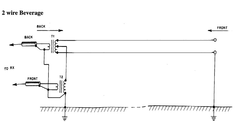 So you want to build a Beverage Antenna. This article offers insights on building a two-wire Beverage antenna for better reception. Key points include using long wire (at least a wavelength, ideally two), keeping it straight and away from vertical conductors, and sloping ends for noise reduction. The author recommends copper clad wire and mentions transformer design considerations for later discussion.
 -
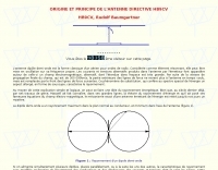 Basics and principles of the HB9CV antenna by Rudolf Baumgartner. This antenna join electric advantages of the two elements direct feeded aerials with the mechanical advantages of the Yagi antennas, in French.
 -
 The ARRL ANTENNA Vol 5 COMPENDIUM features an article detailing two portable 6-meter antennas: a 2-element quad and a 3-element Yagi with telescoping elements. The 2-element quad exhibits a measured gain of **4.2 dB** over a dipole, while the 3-element Yagi achieves **5.8 dB** over a dipole. Both designs prioritize ease of construction and rapid assembly/disassembly for portable operations. Specific dimensions are provided for a 3-element 6-meter quad using #14 bare copper wire. The reflector element diameter is 6.2958 meters, the driven element 6.125 meters, and the director 5.8547 meters. Element spacing is 0.9398 meters between reflector and driven, and 1.1684 meters between driven and director. The SWR is under _1.26:1_ from 50 to 50.4 MHz, with a feed point impedance of 48.75 -j0.13 Ohms at 50.2 MHz, suitable for direct 50 Ohm coax feeding with a current _balun_.
 -
 Radio Scanners Uniden Bearcat, Antennas, CB_Radios, Ni-Cad Batteries, Frequency Books, Accessories, Power Supplies and Cords, FM Two Way Radios, and other Related Merchandise
 -
 Technical reference about Accessories, Amplifiers, Antennas, Cable and Connectors, Filters, Geography, Grounding, Gunk, Matching Networks, Projects, Propagation Info Radios, RFI/EMI, Rotors, Station Setup, Towers.
 -
 You will find on these pages my experiences and results on antennas and local/non-local QRM/noise reduction. Using a broadband vertical active magnetic loop and a home made / designed broadband amplifier. Two vertical magnetic Alford loops are used in an array. Analog and Digital Signal Processing and a dual phase coherent Software Defined Radio (SDR) are used. By PA0SIM
 -
 Automatic Link Establishment (ALE) is a digital signaling protocol enabling HF radio stations to automatically establish communication links, crucial for emergency and disaster relief operations. HFLINK serves as a central international resource for ALE High Frequency Communications, HF Selective Calling (SELCALL), and general HF interoperability. The platform provides extensive information on ALE operation, including frequency networks, band plans, and software like _PCALE_ for amateur radio integration. It also documents significant events such as the _HF Interoperability Exercise (HFIE)_ and the _Global Simulated Emergency Test (GlobalSET)_, which allow ham operators to gain real-world experience in interoperable HF communications, often using specific frequencies like the USA 5 MHz ALE simplex frequency 5371.5 kHz USB. The site features articles on antenna types popular among ALE users, such as autotuners and broadband antennas like the _T2FD_ and the Broadband Butterfly Terminated Dipole (BBTD).
 -
 The BV6 50 MHz Yagis resource details the construction of two distinct Yagi antenna designs for the 6-meter band, specifically a 1-wavelength (1wl) model and a 2.1-wavelength (2.1wl) model. The 1wl Yagi, with a boom length of 5.850m, achieves a gain of **9.4 dBd**, while the 2.1wl Yagi, spanning 12.90m, boasts a gain of **11.9 dBd**. These designs adhere to a proven methodology for optimizing current slope and maintaining constant phase delay across parasitic elements, ensuring high gain per boom length and an _excellent pattern_. Both designs target a 50-ohm input impedance, facilitating straightforward feeding with a robust folded dipole. Final verification using NEC-II software confirmed the antennas' exceptional stacking capabilities, yielding stacking gains exceeding **5.8 dB** for a 2x2 array with minimal mutual detuning. The resource provides common mechanical data, including boom and element diameters, and specifies element lengths corrected for boom diameter. While the original _DUBUS Technik V_ publication contained incorrect element lengths, this resource provides the accurate dimensions for proper construction, emphasizing the use of readily available materials for cost-effective amateur radio deployment.
 -
 Simple gain antennas for the beginner, a 2 element HF yagi antenna
 -
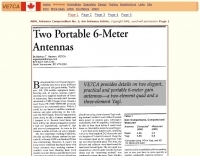 VE7CA reprint an interesting article taken from arrl antenna compendium. Two elegant practical and portable 6-meter gain antennas, a two-element quad and a tree-element Yagi antenna for 50 Mhz-6 meter band
 -
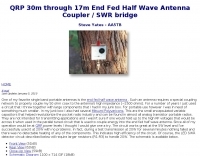 Wire antennas requires a special coupling network to properly couple my 50 ohm coax to the antenna's high impedance (5000 ohms)
 -
 VHF Antenna in a lunchbox. The magnetic loop on two metres band Lloyd Butler VK5BR
 -
 A Center-Fed Half-Wave Dipole is probably the simplest of antennas to construct and use. It is usually suspended between two supports, from it's end insulators, and has the feedline hanging from the center.
 -
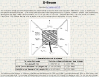 Two element X-Beam is a high-performance broad-band antenna that is ideal for Ham radio operators with limited space. X-Beams are inexpensive and easy to build. The performance of the simple X-beam is amazingly similar to larger, more conventional antennas by 4S7NR
 -
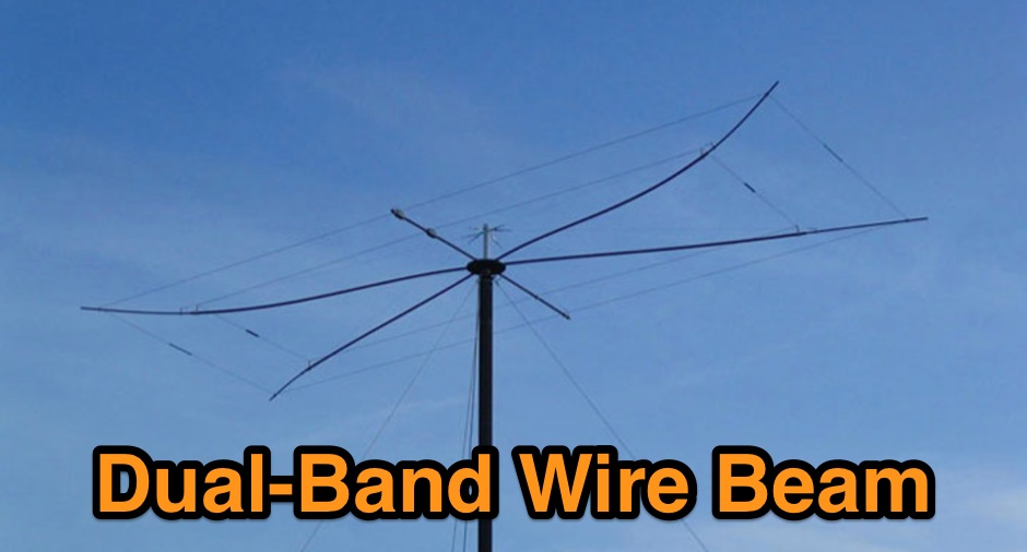 Operating on the 12-meter and 17-meter WARC bands often benefits from directional antennas that offer gain and front-to-back ratio in a compact footprint. This resource details the construction of a dual-band wire beam, specifically a _Moxon Rectangle_ design, for these two bands. It outlines the use of fiberglass tubing for spreaders, _Flexweave_ wire for the elements, and an aluminum hub with die-cast flanges to create a robust structure. The design allows for a single 50-ohm feed point, simplifying station setup and minimizing feedline loss. The project provides specific dimensions and material choices, enabling a homebrewer to replicate the antenna. While inspired by L.B. Cebik's (W4RNL) theoretical work, this implementation focuses on practical construction techniques for a physical build. The resulting antenna offers directional characteristics suitable for DXing and contesting on 12m and 17m, providing an alternative to full-sized Yagis or compromise verticals, particularly for those with limited space.
 -
 Match & display imped of antennas, can graphically visualize and compare two sets of measured impedances simultaneously.
 -
 Constructing a linear focus parabolic antenna for WiFi operation involves precise metalwork, as detailed in this project. The author, AB9IL, shares a build that can be completed in a few hours, emphasizing the hands-on process of shaping and assembling metal components. This design aims to provide enhanced signal range for 2.4 GHz wireless networks, a common challenge in many ham shacks and home setups. The project outlines the practical steps required, from initial measurements to the final assembly, including cutting, bending, and bolting various metal parts. While specific gain figures are not provided, the parabolic design inherently offers significant _directional gain_ compared to omnidirectional antennas, making it suitable for point-to-point links or extending network coverage over distances. The construction process focuses on readily available materials and basic shop tools, aligning with the DIY spirit prevalent in amateur radio. This antenna project is presented as a straightforward build, requiring attention to detail in fabrication to achieve optimal performance.
 -
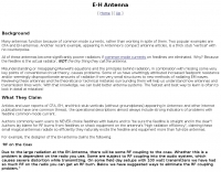
 Various tests and designs, with photos of home made EH Antennas,simple and networked, and also sone CAN Antennas.
 -
 For radio amateurs seeking compact, directional antenna solutions, the Moxon Rectangle offers an attractive alternative to traditional two-element Yagis. This resource compiles several articles by L. B. Cebik, W4RNL, exploring the **Moxon Rectangle** design, which provides gain comparable to a full-size two-element array but with a significantly improved **front-to-back ratio** and a direct 50-Ohm feedpoint match. The collection covers both wire arrays, particularly for lower HF bands, and rotatable aluminum beam constructions, addressing various aspects of this popular antenna configuration. The articles delve into specific band applications, including designs for 10 meters, 40 meters, and 2 meters, alongside discussions on multi-banding techniques and pattern characteristics. Comparisons are drawn between the Moxon and other antenna types, such as VK2ABQ Squares, highlighting the Moxon's advantages in terms of size and performance. Practical construction notes are provided for both wire and aluminum versions, offering insights into building these antennas for different operating environments.
 -
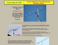 For two purposes a Cross-Yagi can be useful Satellite work or if you need both vertical and horizontal polarization for terrestrial contacts
 -
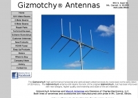 The Charles Gizmotchy high performance horizontal and vertical beam antennas. Two, Six, Ten and eleven meters antennas
 -
 A compact Beam Antenna That Can Be Built At Home. Made with lightweight wooden "X" frame with two folded and linear loaded wire elements. The two elements are approximately a half-wave each.
 -
 JJ0DRC's HF multi-band delta loop antenna project, initially conceived during the waning peak of Cycle 23, addresses the common challenge of achieving effective DX operation from a small residential lot in Japan. Dissatisfied with a ground plane antenna's performance in SSB pile-ups, the author sought a beam-like solution without a tower, drawing inspiration from a JJ1VKL article in CQ Ham Radio Sep. 2000. The antenna, constructed in October 2000, employs two 7.2-meter fishing rods (37% carbon fiber, reinforced with cyano-acrylate glue and aluminum tape) and 1mm enameled wire, fed by an Icom AH-4 external antenna tuner. While the exact beam pattern remains unmeasured, JJ0DRC observed a significantly higher callback rate compared to dipole antennas, particularly on higher bands. The system's circumference length of 15-20m is crucial for maintaining a good beam pattern across HF bands, though performance on lower bands like 80m, 40m, and 30m becomes less directional as the length deviates from a full wavelength. Ongoing maintenance addressed degradation issues, including aluminum tape cracking and wire breakage at connection points due to strong winds (often exceeding 10-15m/s in winter). The author reinforced rod connections with IRECTOR PIPE SYSTEM components and INSU-ROCK ties, and improved wire attachment methods using Cremona rope and epoxy bond to enhance durability.
 -
 Over **10 million** antennas and flags have been sold worldwide by Firestik Antenna Company, a veteran-owned manufacturer specializing in both CB and amateur radio communication products. Their offerings include a range of antennas, mounting accessories, and coaxial cables, designed for various mobile and fixed applications. The company provides technical support and maintains a network of dealers for product availability. Firestik products are known for their fiberglass construction, which is evident in their _Firestik_ and _Firefly_ antenna lines. The company also produces unique items like the "342 mile per hour Firestik flag," highlighting their diverse manufacturing capabilities beyond just radio antennas. They emphasize their commitment to quality and customer service, including direct technical assistance. The company is located in Tempe, Arizona, and operates under the registered trademark of _Pal International Corporation_. They actively protect their brand, including variations like Firestick and Firestix, ensuring proper representation of their products in the market.
 -
 A vertical dipole for 10, 15, 20 and 40 meters made adapting two Hustler Model 6-BTV antennas by w6sdo
 -
 This resource details the conversion of an 80m elevated vertical antenna to include 160m operation, focusing on a relay-switched design over a trap-based approach. It presents specific feedpoint impedance values, such as **32 ohms** for 80m and **14 ohms** for 160m, and discusses the challenges of SWR drift encountered with the prior trap system during RTTY contesting. The article thoroughly explains the design choices for elevated radials, referencing _N6LF QEX data_ to debunk common myths regarding radial length and height, demonstrating that non-resonant radials can offer superior current uniformity. The construction section provides practical insights into building the vertical, including guying strategies, material selection from scrap pipe, and weatherproofing the relay assembly. It highlights the use of a common mode choke for the relay switching line, measuring approximately 5K ohms on both 160m and 80m, and details the L/C matching network's role in achieving a 50-ohm match at the end of a 300-foot RG-11 run. The author describes a precise VNA-based radial trimming procedure, achieving resonant values within a 3 KHz range. The content emphasizes the practical application of theoretical antenna principles, particularly concerning the interaction between the vertical element, cap hats, and the matching network. It offers a candid assessment of component selection, such as using junkbox parts and acknowledging the need for future upgrades to static drain resistors. The article serves as a comprehensive case study for advanced antenna builders tackling multi-band vertical designs.
 -
 Demonstrates the design and construction of a 9-element Yagi antenna for the **70 cm band** (432 MHz), based on the DK7ZB concept. The resource details EZNEC+ calculations for a single antenna, providing gain, sidelobe suppression, and front-to-back ratio figures. It also presents a comprehensive analysis of stacking two such antennas, including optimal stacking distance (1000 mm) and the resulting performance enhancements for the stacked array, such as an increased gain of 17.03 dBi. The article includes detailed drawings, wire file dimensions in millimeters, and azimuth/elevation plots for both single and stacked configurations. Practical construction steps are documented with original photographs, illustrating element mounting, the **28 Ohm matching system** using two quarter-wave 75 Ohm transmission lines, and the critical N-connector wiring. It also covers the iterative process of fine-tuning the driven element length to achieve a return loss of 20 dB, validating the EZNEC+ simulation results with actual measurements.
 -
 One specific challenge in the KazShack, operating Single Operator Two Radios (SO2R), involved sharing a K9AY receive antenna between two transceivers without direct RF connection or manual feedline swapping. The solution, detailed in this project, adapts the **W3LPL RX bandpass filter** design to split 160m and 80m signals, feeding them to separate radio inputs while maintaining isolation. This approach also addresses the issue of strong broadcast band interference from a nearby 50KW WPTF transmitter on 680kc. The construction utilizes T-50-3 toroids and NP0 ceramic capacitors, built in a "dead bug" style on copper clad board. Each band's filter coils are identical and resonated to the desired frequency using an MFJ-259 antenna analyzer. A single DPDT relay, controlled by a remote toggle switch mounted on an aluminum panel, facilitates quick band switching between radios, simplifying low-band operations. While some signal loss is noted, the expected lower noise levels from the receive antenna are anticipated to compensate, potentially reducing the need for constant volume adjustments during toggling between transmit and receive antennas.
 -
 Solves antenna matching problem with two phased antennas. Stacked rotary beams are popular. However, connecting two 50 Ohm antennas together presents some problems.
 -
 Many antennas function because of common mode currents, rather than working in spite of them. Two popular examples are CFA and EH antennas. Another recent example, appearing in Antennex's compact antenna articles, is a thick stub "vertical" with no counterpoise.
 -
 About beverage antennas, Enhanced F/B Beverages, Bandwidth of Directivity, arrays. This article describes two phasing systems for Beverage antennas that improve directivity and cancel rearward signals. These systems use lossy elements and require minimal components to achieve broadband performance.
 -
 The **HFRadioSales.au** resource provides a commercial outlet for amateur and commercial radio operators seeking HF SSB equipment and related services. It focuses on the Australian market, offering new and refurbished transceivers, antennas, tuners, and a wide array of spare parts for brands like Codan, Barrett, and Qmac. The site details its role as a licensed dealer for new Barrett Communications and Codan radio and antenna systems, including specific models such as the Barrett 4050, 2050, and 950, and Codan Envoy and NGT series. This platform supports various applications, including vehicle, 4WD, outback, marine, and base station setups, catering to networks like HF Radio Club, VKS737, and RFDS. It also features commercial-grade antennas from Bushcomm, such as the BBA100C and SWC100, available for fast shipping from their Queensland warehouse. The site includes an FAQ section with general information on mobile HF communications in Australia and timelines for specific transceiver models.
 -
 DK7ZB provides detailed construction plans for Moxon antennas utilizing tapered aluminum tubing, specifically outlining dimensions for 50 MHz, 28 MHz, 24 MHz, and 21 MHz bands. The resource emphasizes maintaining specific taper lengths for optimal performance and describes a tuning method involving symmetrical element shifts. It also addresses stacking considerations, noting that two Moxons can be stacked 1m apart with a 90° rotation to avoid severe detuning, unlike co-planar mounting. Performance figures for the 50-MHz Moxon include a gain of **4.1 dBd** and a front-to-back ratio of _30 dB_. The construction utilizes copper fittings for element connections, with a recommendation to varnish edges against corrosion. The page features images of built antennas by _DK8UH_ and VK2QO, illustrating practical implementations for the 6-meter and 10-meter bands, respectively.
 -
 Demonstrates the design principles and performance characteristics of **corner reflector antennas**, emphasizing their high gain and directional properties. It covers critical design factors such as the corner angle and the spacing between the radiating dipole and the reflector vertex. The resource explains how reducing the corner angle increases gain but lowers feed impedance, making matching more challenging. Practical angles of 90 degrees or 60 degrees are discussed, with 90 degrees offering easier impedance matching despite slightly lower gain. Details key design considerations, including reflector side length exceeding two wavelengths and reflector width greater than one wavelength for a half-wave radiator. It specifies reflector construction using wire netting, sheet metal, or parallel metal spines spaced less than 0.1 wavelength. The article provides a table with general dimensions for UHF and VHF bands, noting typical impedance values of 50 to 75 ohms and expected SWR of 1.7:1 on the lower band edge. Adjustable radiator-to-vertex spacing is highlighted as crucial for final tuning.
 -
 The G5RV multiband HF antenna, designed by Louis Varney (G5RV) in 1946, is a popular compromise antenna offering good overall performance on most HF bands when paired with an external antenna tuner. The basic full-size G5RV measures 102 feet across the top for 80 through 10 meter operation and is fed at the center via a 34-foot low-loss feed-stub. This interaction between the radiating section and the feed-stub facilitates matching across 80-10 meters with a standard tuner, often eliminating the need for ladder line directly to the shack. The antenna's design center frequency is 14.150 MHz, configured as a 3/2-wave dipole on 20 meters, with its 102-foot length derived from long-wire antenna formulas. Construction details emphasize the matching section, which can be open wire, ladder line (window-type), or TV twin lead. Each type has a specific velocity factor (VF) affecting its physical length for an electrical half-wave on 14 MHz; for instance, open wire requires 33.7 feet (VF 0.97), ladder line 31.3 feet (VF 0.90), and TV twin lead 28.5 feet (VF 0.82). The article provides formulas for calculating these lengths and discusses the antenna's behavior on individual bands, from 3.5 MHz where it acts as a shortened dipole, to 28 MHz where it functions as two three-half-wave long-wire antennas fed in-phase. Practical construction notes include recommendations for vertical descent of the matching section, sealing the coax junction, providing strain relief, and winding a coaxial choke coil to mitigate common mode current. The resource also presents dimensions for double-size (204 ft) and half-size (51 ft) G5RV versions, along with their corresponding matching section lengths for various line types, making it a versatile reference for hams considering this classic wire antenna.
 -
 The NCDXF/IARU International Beacon Project operates a worldwide network of 18 high-frequency radio beacons, continuously transmitting on 14.100, 18.110, 21.150, 24.930, and 28.200 MHz. These beacons, initially launched in 1979 with a single station and expanded to the current 18-beacon system in 1995, provide reliable signals for both amateur and commercial users to assess current **ionospheric propagation** conditions. The system's design, construction, and operation are managed by volunteers, covering hardware and shipping costs. The resource details the evolution of the beacon network, including the transition from Kenwood TS-50s transmitters to Icom IC-7200 radios with a new controller design implemented in 2015. It explains how listening for these 100-watt signals, transmitted to vertical antennas, allows operators to determine band openings and optimal propagation paths globally. The content also references three QST articles providing historical context and technical specifics of the beacon project. Practical information includes methods for identifying transmitting beacons via a schedule or specialized software like FAROS and Skimmer, which integrates with the **Reverse Beacon Network** for automated monitoring.
 -
 Experiments with spiral dipole antennas. Includes two spiral antenna designs for 20 and 40 meters band by KN9B
 -
 A fractional bandwidth of up to 30:1 characterizes spiral antennas, making them highly effective across a very wide frequency range, often from 1 GHz to 30 GHz. The resource details two primary types: the **Log-Periodic Spiral Antenna** and the **Archimedean Spiral Antenna**, defining each with specific polar functions and illustrating their planar configurations. It explains that spiral antennas are typically circularly polarized, with a Half-Power Beamwidth (HPBW) of approximately 70-90 degrees, and a peak radiation direction perpendicular to the spiral plane. The content elaborates on critical design parameters affecting radiation, including the total length (outer radius) for lowest frequency, the flare rate ('a' constant) for optimal radiation versus capacitive behavior, the feed structure (often an infinite balun) for high-frequency operation, and the number of turns (typically 1.5 to 3 turns). It also discusses the theoretical impedance of 188 Ohms for Log-Periodic spirals, derived from Babinet's Principle, noting actual impedances are often 100-150 Ohms. The article presents a simple construction method for an Archimedean spiral, demonstrating VSWR and efficiency measurements. Measurements from a constructed spiral antenna show a VSWR that is fairly constant across the band, albeit with a mismatch loss of about 3 dB. The antenna efficiency remains around -5 dB (31.6%) across its operating range, indicating a decent wideband radiator despite opportunities for optimization.
 -
 This article compares two commercial vertical antennas for the 4-meter amateur radio band: the Watson WVB-70 half-wave and the Sirio CX4-71. The Watson measures 2.03m in length, costs around £40, and exhibited adequate performance but required additional waterproofing after rain affected its VSWR readings. The longer Sirio CX4-71 (3.02m) performed noticeably better, delivering signals approximately 2 S-points stronger than the Watson. The Sirio demonstrated high build quality, a stable 1.2-1.4:1 VSWR, and weather resilience, though minor VSWR fluctuations were observed during rain and frost. Both antennas are half-wave designs requiring no ground plane radials.
 -
 This resource details the four primary functions of a ground system: lightning energy dispersion, equipment safety, RF return path provision for end-fed antennas, and management of induced RF currents. It clarifies that a ground system's effectiveness varies depending on its specific function, noting that a good lightning ground might not be an effective RF ground. The content emphasizes that proper antenna system design, including baluns and appropriate feedline lengths, often negates the need for an RF station ground to mitigate common mode currents or RFI in the shack. The article quantifies lightning energy, stating its peak is in the dozens or hundreds of kilohertz, with damaging energy extending to hundreds of megahertz, and currents reaching thousands of amperes. It recommends solid, wide, smooth copper surfaces for ground leads to achieve low impedance across a wide frequency range. The author, W8JI, shares practical insights from his station, which includes two 300-ft towers and four 130-ft wire verticals, detailing his use of common point grounds and _DX Engineering RR-8 HD_ antenna switches for lightning protection without coaxial surge protectors. Specific examples of antenna systems prone to common mode current problems are listed, such as random wire antennas without proper feedline lengths and off-center fed dipoles. The text also explains how a ground screen or radial system can reduce local noise sensitivity for vertically polarized antennas by covering the lossy earth.
 -
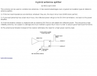 This scheme can be used to combine two antennas
 -
 The collinear J-Pole, often known as the Super-J, does improve the behavior over a regular J-Pole. As many attest, there is an advantage when vertically combining 1/2 radiating sections to have a bit of separation between the half-wave end points. The Super-J has very little separation between the two half-wave radiators.