Search results
Query: verticals antenna
Links: 55 | Categories: 3
-
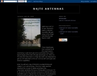
 Details the construction of a J-vertical antenna specifically for the 10-meter band, offering a practical alternative to a _Slim Jim_ design for 28 MHz. The resource outlines the use of aluminum tubing for the half-wave vertical section and coaxial cable for the quarter-wave matching section, providing specific calculations for element lengths based on frequency and coaxial cable velocity factor. It contrasts the performance of the J-vertical with center-fed dipoles and end-fed verticals, noting superior results in previous comparisons. The article further presents a more recent iteration of the J-vertical, constructed using a fiberglass pole and insulated wire, with updated dimensions for 28.8 MHz. It includes practical advice on weatherproofing connections and securing the antenna for durability against adverse conditions, referencing the survival of an original _J Vertical_ during 110 MPH winds in 1987. The SWR performance is reported as 1.1:1 at 28.6 MHz, maintaining below 1.5:1 across 28.3 to 29 MHz.
 -
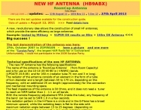 The HB9ABX RoomCap antenna document details the construction and performance characteristics of a compact HF antenna design. It presents a series of comparative field tests conducted between July and September 2005, evaluating the HB9ABX antenna against established designs like the Microvert MV-500, Cushcraft R5/R7000 verticals, and a 5-element DJ2UT Yagi beam. Specific test scenarios include mobile installations, rooftop deployments, and comparisons on 20m, 40m, 80m, and 160m bands, with signal reports from various European and DX stations. The resource emphasizes the antenna's small physical footprint and its claimed efficiency across multiple HF bands. Test results consistently show the HB9ABX antenna performing comparably to, and often outperforming, larger reference antennas in terms of received signal strength, with reported differences of 1 to 2 S-points (6-12 dB) in many contacts. Notably, a 20m DX test on July 26, 2005, indicated the 1.3m HB9ABX radiator yielded 2-3 S-points stronger signals than an R7000 vertical for US DX stations. An August 12, 2005, test on 40m highlighted the HB9ABX's superior signal-to-noise ratio in urban QRM, demonstrating 10-18 dB better performance than an R7000. The document includes specific callsigns, signal reports, and QTHs for each comparison, providing empirical data for the antenna's performance claims.
 -
 End-Fed antennas are NOT balanced systems; but neither are verticals, ground planes, discones, windoms, zepps, Marconis, half-slopers, et al. Additionally, the low-impedance antenna port of your transmitter/receiver is not balanced.
 -
 Low weight Titanium Verticals, Log-Periodics, Yagi antennas, Quads, towers and antenna accessories by Titanex
 -
 Presents the KE4UYP linear-loaded vertical antenna design, which introduces very little loss on 80 or 160 meters, achieving an overall radiation efficiency of 80% to 85%. This design addresses common pitfalls of traditional base-fed verticals by placing the majority of the current at the top of the antenna, eliminating the heavy reliance on extensive ground radial systems. The author's initial 10-meter model, only three feet tall, yielded 5/9 signal reports to Anchorage, AK, and Europe, confirming its effectiveness. The antenna incorporates both vertically and horizontally polarized radiators, with a 1/4 wavelength horizontal counterpoise located at the feed-point, near the top, to create an almost totally omnidirectional pattern with high wave angle horizontally polarized radiation. This dual polarization ensures even illumination across all take-off angles, making it effective for both local contacts and **DXing**. The vertical element is linear loaded, adding capacitance reactance and making it longer than the horizontal element to achieve resonance and raise the feed-point impedance to 50 ohms. Fine-tuning the antenna requires careful adjustment, as tower reactance can vary. The article suggests starting with 80 feet for 80m and 170 feet for 160m for the vertical wire, then trimming for resonance. Bandwidth specifications include 300 kHz under 2:1 **SWR** on 80m and 100 kHz on 160m when suspended between trees, or 150 kHz on 80m when side-mounted on a tower.
 -
 Multi Band Quad,Cushcraft R5, R7, R7000, repair and maintenance, Remote Antenna Switching, Hexagonal Beam, Automatic Band Decoder, Low Band Verticals, Crank-up Tiltover Tower etc
 -
 Programs for common antennas and some experimental, includes, dipoles, quad, Yagi, verticals, discone, jpole skyhoppers and parabolic antennas
 -
 A 2-meter Turnstile antenna, detailed for amateur satellite communication, offers a straightforward build for those looking to engage with orbiting transponders. The author, WB8ERJ, shares his personal design and construction methods, emphasizing the antenna's simplicity and effectiveness for LEO (Low Earth Orbit) satellite work. This design provides a circularly polarized signal, crucial for mitigating _Faraday rotation_ and signal fading often encountered with linearly polarized antennas when tracking satellites. Construction involves readily available materials like PVC pipe and copper wire, making it an accessible project for many hams. The article includes practical advice on element spacing and feed point considerations, drawing from the author's hands-on experience in the shack and field. It highlights the antenna's utility for receiving signals from various amateur satellites, including the popular AO-91 and AO-92. The Turnstile's inherent omnidirectional pattern in the horizontal plane, combined with its circular polarization, yields consistent signal reception, often resulting in **stronger decodes** and **more reliable contacts** compared to basic dipoles or verticals.
 -
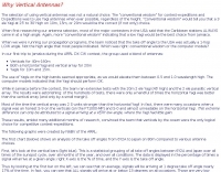
 Why a vertical antenna or longwire antenna might require a balun
 -
 Java script antenna calculators for ground planes, half wave verticals, quad antenna, 5/8th wave vertical antenna, dipole and inverted vee antennas
 -
 End-Fed Half-Wave Antennas (EFHWAs) are analyzed for their utility in portable QRP operations, emphasizing their simplicity, efficiency, and predictable radiation patterns compared to other portable antenna types. The discussion contrasts EFHWAs with vertical antennas, random length wires, and center-fed dipoles, highlighting the common pitfalls of each, such as ground system dependency for verticals and feedline issues for dipoles. The article details the electrical half-wavelength calculation using the formula L (Ft) = 468/F(MHz) and explains how EFHWAs can be resonant on harmonic frequencies, enabling multiband operation. Various deployment configurations are presented, including the inverted L, inverted Vee, sloping wire, and vertical setups, each with specific advantages for radiation angle and polarization. For instance, a vertical EFHWA offers a low angle of radiation suitable for DX contacts without requiring an extensive ground system. The resource also addresses the counterpoise requirements, suggesting a quarter-wavelength wire or connection to a metallic structure for decoupling. A schematic diagram for a simple parallel-tuned circuit tuner, based on the _Rainbow Bridge/Tuner_ design, is provided, detailing component values for 30 and 40 meters, including a 6 microhenry toroidal inductor and a 20-100 picofarad mica compression capacitor. The tuner's adjustment process for SWR matching is also outlined.
 -
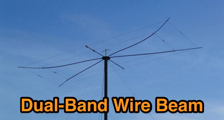 Operating on the 12-meter and 17-meter WARC bands often benefits from directional antennas that offer gain and front-to-back ratio in a compact footprint. This resource details the construction of a dual-band wire beam, specifically a _Moxon Rectangle_ design, for these two bands. It outlines the use of fiberglass tubing for spreaders, _Flexweave_ wire for the elements, and an aluminum hub with die-cast flanges to create a robust structure. The design allows for a single 50-ohm feed point, simplifying station setup and minimizing feedline loss. The project provides specific dimensions and material choices, enabling a homebrewer to replicate the antenna. While inspired by L.B. Cebik's (W4RNL) theoretical work, this implementation focuses on practical construction techniques for a physical build. The resulting antenna offers directional characteristics suitable for DXing and contesting on 12m and 17m, providing an alternative to full-sized Yagis or compromise verticals, particularly for those with limited space.
 -
 A potpourri of 160-Meter vertical antennas and modeling issues, inverted-L, 3-element parasitic array, 1/4-wavelength monopole
 -

-
 In 1999, W5GVE presented a detailed construction article for a 2-meter _DDRR_ antenna, specifically designed for mobile operation. This unique antenna, a Directional Discontinuity Ring Radiator, offers a compact footprint, making it suitable for vehicular mounting where traditional quarter-wave verticals might be impractical. The design emphasizes ease of homebrewing, utilizing readily available materials and basic workshop tools, allowing radio amateurs to build an effective mobile antenna for the 144 MHz band. The article provides insights into the antenna's performance characteristics, noting its low profile and potential for reduced wind loading compared to taller mobile whips. W5GVE's experience with the DDRR design suggests it can provide reliable communications on the 2-meter band, even in challenging mobile environments. The construction details include specific dimensions and assembly steps, guiding the builder through the process of creating a functional antenna. This project offers a practical alternative for hams seeking a discreet yet effective 2-meter mobile antenna, potentially achieving **3 dB** gain over a standard mobile whip.
 -
 G4URH calculations to design your own antennas, ground plane, half wave antennas, Quad Antennas and 5/8 verticals
 -
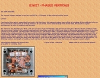
 Experiments with phased wire vertical antennas on 40 meters at VA7ST
 -
 2 element reversible verticals, small footprint, big results.
 -
 NEC4WIN is a 32 bits commercial antenna simulation software based on MININEC3 developed by the Naval Ocean Systems Center in the 70s and 80s. It runs under Windows and can be used to simulate, analyze and optimize wire antennas, beams, verticals, etc. NEC4WIN has limitations. They are the same as Mininec3 on which the engine is based.
 -
 The array consists of 7 vertical antennas arranged as 6 verticals in a hexagon shape plus 1 additional vertical in the center of the hexagon
 -
 GW4ALG's _136 kHz Pages_ document the evolution of vertical antennas for the 2200m band, starting with a prototype mounted on a house wall. This initial design, despite achieving the first **395 km** GM-GW QSO, suffered from significant insulation breakdown, high RF losses due to proximity to the house, and difficult tuning adjustments. The author details the challenges of maintaining resonance and matching with a variometer in the loft, noting that adding three earth spikes offered no measurable improvement over a simple water tap connection. The subsequent experimental 12m vertical, relocated away from the house, significantly reduced dielectric losses and proved far more effective. This antenna enabled GW4ALG to set a world DX record on 136 kHz with a **1916 km** QSO to OH1TN, and an intra-UK record of **703 km** to GM3YXM/P. The resource further explores the use of helium-filled balloons to extend the vertical radiator, achieving heights up to 27m, typically 20m, for enhanced low-band performance. Practical advice on balloon types, inflation, and critical insulation between the wire and balloon is provided, emphasizing safety and avoiding arcing.
 -
 Amateur Radio Station owned by Matt Strelow. The station is designed for competition in the multi-operator multi-transmitter category of high-frequency DX contests. Running with 7 towers 6 rotators, 8 beverage listening antennas, and 4 spotting verticals
 -
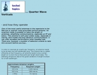 One of the most useful antennas in the repertoire is the Marconi or quarter wave grounded vertical antenna. Its invention made it possible to halve the length of antennas, simplifying communications, especially at HF and below.
 -
 A ATU for beam and vertical antennas by PA0FRI
 -
 This 80M antenna is a pair of raised 1/4-wave verticals
 -
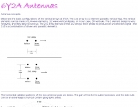 Configurations of the vertical antenna arrays used at 6Y2A
 -
 Demonstrates the construction and implementation of a **two-element phased vertical array** for 40 meters, utilizing _Christman phasing_ techniques. The author, W4NFR, details the process from building individual 1/4-wave aluminum verticals to integrating them into a phased system. The resource covers antenna spacing of 32 feet, elevated radial design, and the critical steps for tuning each vertical to achieve a 1.1:1 SWR before combining them. It also provides insights into calculating precise coax lengths for feedlines and the phasing delay line, emphasizing the use of an MFJ-269 Antenna Analyzer for verification. The finished system exhibits good front-to-back nulls, with an overall SWR ranging from 1.6:1 to 2.2:1, which is managed by an antenna tuner. The project includes detailed photos of the relay box, showing 12 VDC relays capable of handling 5KV, and the control box in the shack for switching between three different antenna pattern configurations. Static bleed-off chokes are incorporated for protection, and the construction emphasizes robust weatherproofing for outdoor elements.
 -
 This project details the construction of a **full-sized 40-meter vertical antenna**, born from a renewed interest in 7 MHz operation and a desire for improved effectiveness over simple dipoles. The author, K5DKZ, initially focused on VHF experimentation, which provided an inventory of aluminum tubing and fiberglass spreaders for this endeavor. Before this vertical, K5DKZ utilized an 80/40 meter inverted-vee trap dipole and a 40-meter broadband dipole, but now primarily uses a pair of full-sized, phased, quarter-wave verticals spaced 35 feet apart for serious 40-meter work. The construction involves a base-heavy design for stability, using a 44.5-inch section of 1-1/4 inch steel TV mast driven into 1-3/8 inch aluminum tubing, insulated by a 105-inch section of Schedule 40 PVC pipe. The assembly reaches 31 feet, close to the 32 feet required for a quarter-wavelength on 40 meters, with fine-tuning achieved by winding wire onto a fiberglass spreader. The design is explicitly presented as a foundation for a two-element 40-meter Yagi beam, outlining modifications like substituting aluminum for steel in the base and using an inductive hairpin match for the driven element. The article also discusses tuning considerations for a large 40-meter beam, noting the 100 to 200 kHz upward frequency shift when raised, and suggesting methods for installation on a tower. The author emphasizes the cost-effectiveness and good performance of the monopole approach, especially when multiple verticals are needed.
 -
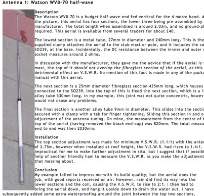
 This article compares two commercial vertical antennas for the 4-meter amateur radio band: the Watson WVB-70 half-wave and the Sirio CX4-71. The Watson measures 2.03m in length, costs around £40, and exhibited adequate performance but required additional waterproofing after rain affected its VSWR readings. The longer Sirio CX4-71 (3.02m) performed noticeably better, delivering signals approximately 2 S-points stronger than the Watson. The Sirio demonstrated high build quality, a stable 1.2-1.4:1 VSWR, and weather resilience, though minor VSWR fluctuations were observed during rain and frost. Both antennas are half-wave designs requiring no ground plane radials.
 -
 This resource details the four primary functions of a ground system: lightning energy dispersion, equipment safety, RF return path provision for end-fed antennas, and management of induced RF currents. It clarifies that a ground system's effectiveness varies depending on its specific function, noting that a good lightning ground might not be an effective RF ground. The content emphasizes that proper antenna system design, including baluns and appropriate feedline lengths, often negates the need for an RF station ground to mitigate common mode currents or RFI in the shack. The article quantifies lightning energy, stating its peak is in the dozens or hundreds of kilohertz, with damaging energy extending to hundreds of megahertz, and currents reaching thousands of amperes. It recommends solid, wide, smooth copper surfaces for ground leads to achieve low impedance across a wide frequency range. The author, W8JI, shares practical insights from his station, which includes two 300-ft towers and four 130-ft wire verticals, detailing his use of common point grounds and _DX Engineering RR-8 HD_ antenna switches for lightning protection without coaxial surge protectors. Specific examples of antenna systems prone to common mode current problems are listed, such as random wire antennas without proper feedline lengths and off-center fed dipoles. The text also explains how a ground screen or radial system can reduce local noise sensitivity for vertically polarized antennas by covering the lossy earth.
 -
 Phased wire vertical antennas for 40 meters band
 -
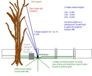 An indeal stealth antenna made by multiple quarter wave verticals, supported by a tree.
 -
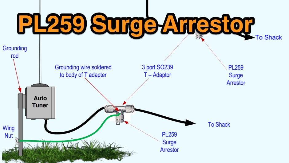 Limiting static surges on dipoles, verticals or end fed antennas
 -

-
-
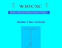 Double T Bar Vertical antenna are vertical antenna with cross bars on the top and bottom. These crossbars provide capacitance loading thus reducing the size of the antenna
 -
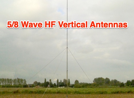 The advantage of 5/8 wave antenna is that it has the lowest angle of radiation and has about 1dB more gain when compared to 1/4 and 1/2 verticals. So the 5/8 should be the favourite choice for DX.
 -
 A 220-ft tower that has five catenary lines, each about 500 feet long. Four of these lines, running NE, SE, SW, and NW support four 1/4-wavelength wire verticals used in a 160-meter four-square antenna.
 -
 Maltronix, HF antennas, dipoles and verticals, switching power supply, power distribution, antenna switch
 -
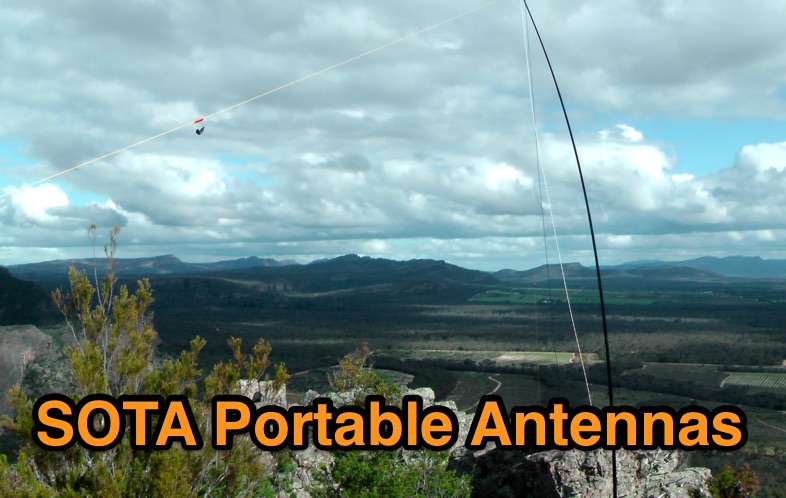 A review of some portable antennas for SOTA operations, including linked dipoles, end-fed, verticals
 -
 K1JJ presents a compilation of insights regarding vertical radial ground systems, specifically applied to 160m vertical arrays. The resource details 19 distinct observations and recommendations, emphasizing that ground radials primarily reduce ground losses rather than influencing pattern formation. It explains that RF current flows inefficiently through average soil, necessitating copper radials to create a low-resistance path back to the antenna base. The content suggests that **50-60 radials** are generally sufficient to achieve optimal efficiency, with diminishing returns beyond that number, and that radials should be laid on the surface for best performance. The discussion also addresses practical aspects such as wire gauge, installation techniques using 'U' shaped staples, and methods for connecting radials in multi-element arrays. It highlights the importance of radial length, stating that 1/4 wave radials are a crucial minimum, and that for 160m, radials should be at least _100 feet_ long. The resource critically examines the efficacy of elevated radials versus ground radials, noting that while a few elevated radials may suffice for VHF, HF applications, particularly on 160m, require extensive ground radial systems to efficiently collect RF currents in the near field. It also touches on the impact of radial systems on parasitic elements and the significance of symmetrical radial patterns for minimizing losses. Further practical advice includes wire type recommendations, proper soldering and weatherproofing techniques for radial connections, and considerations for integrating steel towers into the ground system. The author shares personal experience with installing 60 quarter-wave and half-wave radials under each of three in-line verticals, expressing satisfaction with the results.
 -
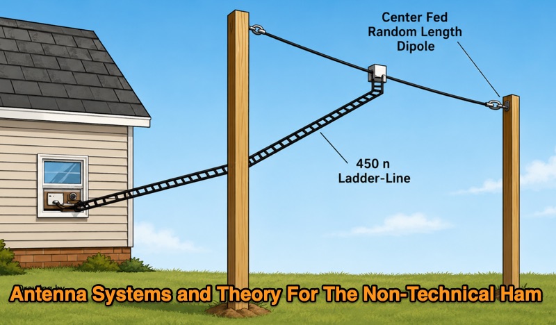 The 60-page PDF document, "Antenna Systems and Theory For The Non-Technical Ham" by Jim Abercrombie, N4JA, provides a foundational understanding of antenna systems. It explains basic antenna theory, including how antennas work, electromagnetic wave polarization, and the role of frequency. The resource details various antenna types such as flat top dipoles, inverted-V dipoles, shortened loaded dipoles, G5RV dipoles, Carolina Windoms, and end-fed configurations. Vertical antennas, including ground-mounted trapped verticals and inverted-L verticals, are also covered. Directional beam antennas like monoband Yagis, cubical quads, and log-periodic arrays are discussed. Propagation modes, including ground-wave, direct wave, and skywave propagation, are explained in detail, with specific attention to the D, E, and F layers of the ionosphere and their effects on HF communication. Technical concepts such as standing wave ratio, decibels, resistance, and reactance are defined, along with calculations for half-wave resonant dipole lengths. The document addresses feed-line radiation, balun applications, and critical antenna and tower safety considerations. It aims to dispel common antenna myths and educate hams on making informed antenna choices.
 -
 A comparison of commercial 4m verticals by by Ian Hogan G6TGO
 -
-
 This article provides a detailed guide on how to build a no holes roof mount for ham radio antennas. The author shares their design that can hold 2 masts and offers tips on installation. The mount is versatile and can handle small 144 Mhz or 432 Mhz beams, as well as small verticals. With adjustable angles and spacing, the mount can be customized to fit different roof types. Additionally, the author suggests affordable options for obtaining Dish antenna mounts. Overall, this DIY project offers a cost-effective solution for ham radio operators looking to mount antennas on their roofs.
 -
 Experiments on vertical antennas for HF bands.
 -
 This Field Day Vertical Antenna project is the result of many years of attending various field day sites and realizing that what was needed is a simple, easy to assemble vertical antenna. The design of this Field Day Antenna is not very novel and leverages ideas from Butternut verticals and ARRL publications. The one essential requirement was that the antenna can be raised by just one person. The design of this Field Day Antenna is an above ground mounted ground plane vertical.
 -
 Steve Nichols, G0KYA, presents a practical examination of ground systems for vertical antennas, drawing heavily on the empirical research of Rudy Severns, N6LF. He explains that a robust radial field is crucial for ground-dependent verticals, effectively replacing the antenna's "missing half" and mitigating severe RF absorption in lossy soil. Nichols clarifies that surface radials do not strictly require a quarter-wavelength; instead, deploying a minimum of 16 to 32 shorter wires often yields superior results compared to fewer, longer ones. The presentation also addresses the common SWR paradox: a poor ground might show a perfect 1:1 match, but adding radials, while potentially raising the SWR to around 1.4:1, significantly improves true radiation efficiency. Nichols defines counterpoises as elevated wire networks that substitute for earth connections, offering solutions for limited-space installations, such as the **Folded Counterpoise (FCP)** for 160 meters. This resource provides actionable engineering data for optimizing vertical antenna performance.
 -
 Operating from Banana Island, Sierra Leone (AF-037), the 9L2019 DXpedition by F6KOP and a ten-operator team used the callsign 9LY1JM from January 9-21, 2019. This detailed report covers the logistical challenges, including securing visas and licenses with local assistance from Mark 9L1YXJ and Gregory of Dalton’s Guest House. The team deployed monoband quarter-wave verticals on the beach and two Beverage on Ground (BOG) antennas for Europe/Asia and the USA, operating four stations simultaneously. Technical hurdles encountered included high tides submerging antennas, requiring repositioning, and persistent QRM between closely spaced stations, mitigated by doubling filters. CW signal irregularities at 30-32 WPM were resolved by PC and WINTEST restarts. A significant FT8 logging bug was identified and corrected with on-site software. Despite these issues, the team logged over 4,000 QSOs in the first 24 hours, averaging 5,000 QSOs daily, with a peak of over 6,000 in one day. Propagation varied, with excellent 160m conditions on January 12 yielding over 750 QSOs, and a later four-hour opening pushing the 160m total past 1,600. High bands were challenging due to low solar activity, but mid-bands provided intense pileups and rapid continent-wide contacts. The DXpedition concluded with nearly 50,000 QSOs, including a successful school QSO with Collège Doisneau de Sarralbe (57), managed by F1ULQ and F6KFT.
 -
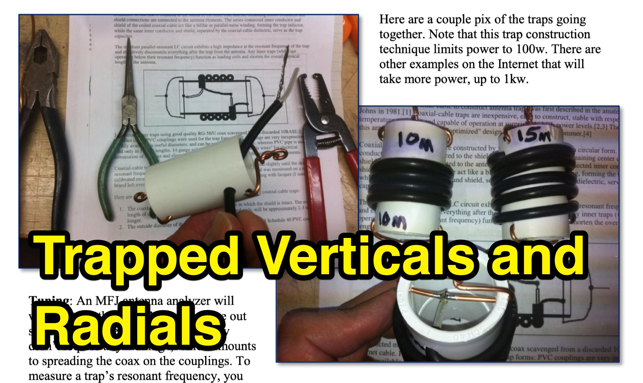 This PDF document provides detailed information on the design, construction, and tuning of trapped vertical antennas with radials for ham radio operators. It covers the theory behind trapped antennas, practical considerations for installation, and tips for optimizing performance. Whether you are a beginner looking to build your first HF antenna or an experienced operator seeking to improve your station setup, this guide offers valuable insights and instructions. By understanding the principles outlined in this document, hams can enhance their operating experience and make the most of their radio communication capabilities.