Search results
Query: 4 square
Links: 130 | Categories: 4
-
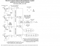 N6RK receive 4 square antenna with transformer coupled antennas and true hibrid combiner
 -
 WorkedGrids is a Windows application that displays a map showing the amateur radio grid squares contacted and logged in using a third-party logging program. WorkedGrids uses colors to display information on a per-band basis. Up to four bands can be displayed concurrently by VE2ZAZ Bert
 -
 This document details the design and construction of a Vinecom 6N4 dual-band Yagi antenna for the 50MHz (6-meter) and 70MHz (4-meter) amateur radio bands. The antenna features 9 total elements (4 elements for 50MHz, 5 elements for 70MHz) on a 4.236-meter aluminum boom. Computer simulations using MMANA software predict 7.21 dBd gain on both bands with front-to-back ratios of 16.01dB (6m) and 15.37dB (4m). The design uses 12.7mm diameter elements mounted on a 32mm square boom, weighing 5.7kg total. Practical measurements with an MFJ-269 analyzer confirmed good SWR performance across both bands after element length adjustments.
 -
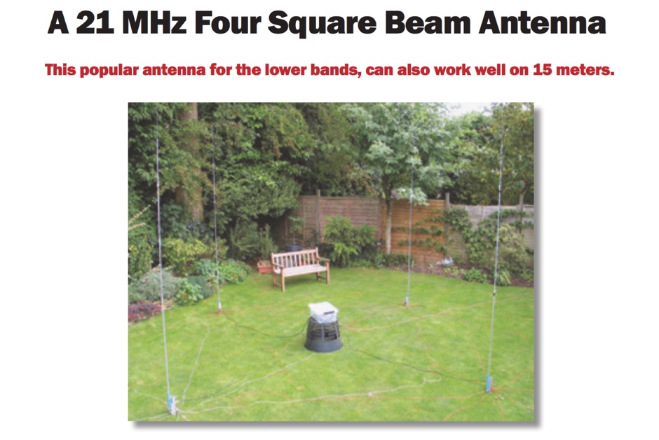 A 21 MHz Four Square Beam Antenna This popular antenna for the lower bands, can also work well on 15 meters, QST Article
 -
 Displays amateur radio grid squares worked from third-party logging programs, providing a visual representation of contacts on a world map. This Windows application uses colors to differentiate up to four bands concurrently, calculating the total number of grid squares worked per band. It reads plain-text log files, including fixed-width, character-delimited, ADIF, and Cabrillo formats, dynamically updating the map as log files are saved during contests or general operation. Primarily targeting **VHF** and above operators, WorkedGrids aids in grid square collection for contesting and awards. The software offers a fixed-resolution continental viewpoint, zoom-in capabilities, and supports printing or copying the map to the clipboard. It operates on Windows 95 through Windows 11, requiring minimal CPU and RAM, and features a non-invasive installation. The program has undergone several updates, with version 7 released on March 3, 2024, addressing minor fixes and improving stability.
 -
-
 Demonstrates the adaptation and construction of a 7-element DK7ZB Yagi antenna for the 4-meter band (70 MHz), utilizing components from a defunct 2-meter CUE DEE Yagi. The resource details the modifications made to the original DK7ZB design to fit the shorter CUE DEE boom length, specifically adjusting element lengths for 6mm rod elements while reusing existing mounting holes for the reflector and last director. It provides precise element lengths for the reflector, dipole (12mm aluminum tube), and five directors, along with a note on cutting elements for transport. The article includes a 4NEC2 simulation file for performance analysis and an SWR plot, confirming the antenna's electrical characteristics. It also specifies the calculation for the quarter-wavelength matching cable using SAT752F coaxial cable, resulting in a 909mm length. Practical application is shown with the finished antenna in operation at JO20XC, listing several activated Maidenhead squares such as JO56PA and JP40KS, validating its effectiveness for portable 70 MHz operations.
 -
 This PDF document details the construction of a **70 MHz** Big Wheel antenna, a horizontally polarized omnidirectional array. The design utilizes three full-wave loops, each approximately **2160 mm** in diameter, arranged in a triangular configuration. The resource provides mechanical dimensions for the antenna elements and a comprehensive bill of materials, specifying component quantities and types, such as M8 stainless steel bolts, 15x15x1.5 mm square aluminum tubing for spacers, and 8 mm aluminum rod for the arcs. The central hub is constructed from two 160x160x8 mm aluminum plates, with four 40 mm long polyamide insulators supporting the radiating elements. The feed system incorporates a 50 mm diameter aluminum pipe for mounting and a matching stub constructed from a 120x20x2 mm aluminum sheet, connected via M8x10 mm bolts. The resource includes a diagram illustrating the mechanical dimensions and assembly points, including the N-connector fixing point and the center conductor attachment. The project was published on May 25, 2011, by Peter OE5MPL and Rudi OE5VRL. DXZone Focus: PDF | 70 MHz Big Wheel | Mechanical Dimensions | **2160 mm** loop diameter
 -
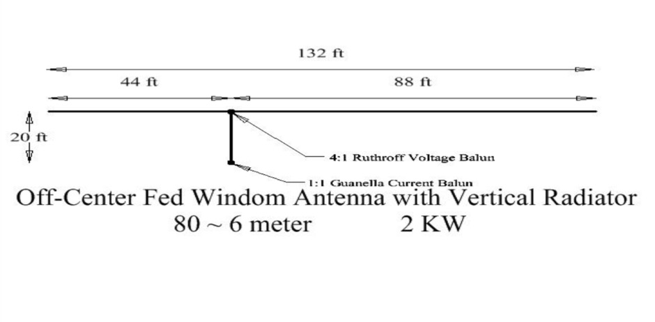 80 to 6 meters, 2 KW, designed to be used at heights of only 25 to 45 feet, includes a twenty foot long vertical radiator
 -
 Calculating the length of a resonant square quad loop
 -
 "Learn about PIC Microcontrollers from our Books ""Easy PIC'n"" and ""PIC'n Up The Pace"" See tables of contents for our books at our web site."
 -
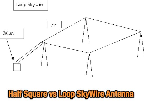 An article at NFARL web site about differences in setting up a half-square antenna versus a Loop Skywire by W4QO
 -
 This large, colorful wall map features current geographic detail and labels, grid squares, call sign prefixes, boundaries and more.
 -
 A eham article on a square copper dipole antenna for 50 MHz by K0FF
 -
 Over 100 amateur radio beacon audio files are presented, offering a direct auditory experience of propagation conditions across a wide spectrum of frequencies, from 1.8 MHz to 47 GHz. These recordings, primarily captured by IW3FZQ and IK3NWX, document signals from beacons such as DK0WCY, IY4M, GB3RAL, and S55ZRS, providing a valuable resource for **propagation study** and **beacon monitoring**. Each entry in the list specifies the beacon's callsign, its operating frequency in kHz, and the recording operator. This compilation includes signals from beacons located in various grid squares like JN55VF, JO44VQ, and IO91IN, illustrating diverse geographical origins. The frequencies covered span the 160m, 80m, 40m, 30m, 20m, 17m, 15m, 12m, 10m, 6m, 4m, 2m, 70cm, 23cm, 6cm, 3cm, 1.2cm, and 6mm amateur bands. Users can listen to these recordings to identify characteristic beacon tones and observe signal strength variations. The resource also invites other radio amateurs to contribute their own beacon audio files, fostering a collaborative archive of propagation data. The last update to this collection was on March 24, 2009, indicating a historical snapshot of beacon activity. Accessing the files requires the Real Player software.
 -
 The resource provides specific information regarding amateur radio operations from various French islands, focusing on geographical and visual data. It includes photographic documentation of locations and detailed maps, which are crucial for operators planning DXpeditions or seeking to understand the unique challenges and opportunities presented by island activations. The content aims to support enthusiasts interested in rare grid squares and IOTA (Islands On The Air) awards. While currently under maintenance, the site's stated future enhancements include QSL card examples, which would offer practical insights into confirmation processes for these specific entities. The emphasis on French islands distinguishes it from more general DX resources, providing a concentrated body of information for a niche but active segment of the amateur radio community, particularly those pursuing island-specific operating awards.
 -
 PSELab is a freeware Windows application useful to estimate power spectrum and short-time spectral distribution of signals. The application uses periodogram, least squares Prony, Burg, covariance, MUSIC and some other methods. To estimate short-time spectral distribution, the application uses short Time Fourier transform, pseudo-Wigner-Ville transform, least squares Prony, Burg, covariance, MUSIC and some other methods.
 -
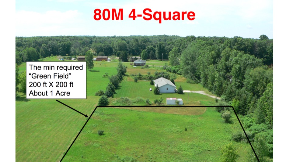 An antenna project to obtain a bigger signal on the 80 Meter (3.5 to 3.8 MHz) amateur radio band
 -
 Hi-Z Antennas offers specialized high-impedance receiving systems, primarily focusing on phased vertical arrays for HF reception. Their product line includes preamplifiers designed for shortened vertical antennas, featuring optimized 15dB gain and array-matched characteristics. These components are engineered to enhance weak signal reception and improve signal-to-noise ratio across the HF spectrum. The company provides controllers for managing multiple vertical elements in a phased array configuration, enabling directional reception patterns. These systems are particularly effective for mitigating local noise and interference, a common challenge in urban and suburban operating environments. Specific offerings include solutions for 160-meter and 80-meter bands, addressing the unique requirements of low-band DXing. Technical details often reference components like the 2N3866 transistor in preamp designs and discuss concepts such as out-of-band attenuation. The focus remains on optimizing receiving antenna performance through impedance matching and active amplification, rather than transmit capabilities.
 -
 A 38-foot Tristao Tower, similar to the U.S. Tower HDX538, was installed twice by the author, first in 1980 and then reinstalled in 1989. The resource details the challenges of self-performing heavy construction tasks like breaking concrete and digging a 3' x 3' x 6' deep footing, contrasting it with hiring professionals for the second installation. It highlights the financial and physical costs associated with DIY tower foundation work, noting a rebar cage cost of $65 in 1980 versus $150-$175 today, and the expense of tools for bending rebar. The content emphasizes the critical importance of obtaining building permits, recounting how a permit in Buena Park, California, nullified a neighbor's complaint about TVI. It also discusses the necessity of adhering to local building codes, such as the 1975 UBC and the subsequent 1985 UBC recertification requirement, which reduced the allowed antenna wind loading from 30 square feet to 20 square feet for the author's _KT34A_ Yagi. The footing depth also increased from 6 feet to 6.5 feet under the newer code. Practical advice includes hiring licensed contractors for specialized work, delaying antenna installation for a month after raising the tower, and verifying buried utilities before any excavation. The author provides specific examples of utility location services like _DigAlert_ in California, underscoring the legal and safety implications of neglecting this step. The narrative is grounded in personal experience, offering a realistic perspective on tower projects.
 -
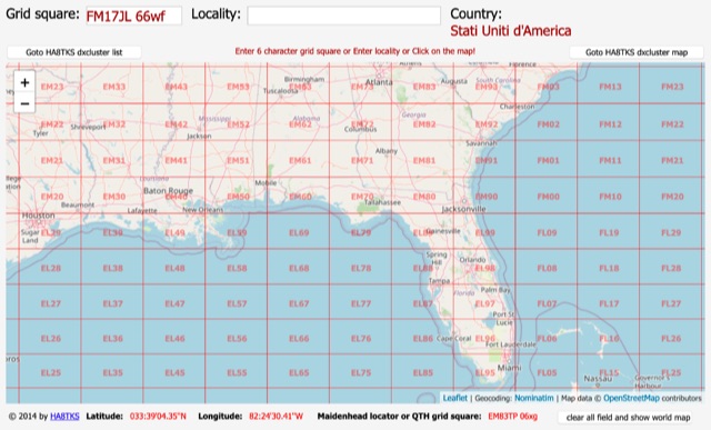 An online interactive grid square map made with openstreet map. Just point and click and zoom in to determine an accurate grid square locator till 10 digit resolution
 -
 A 220-ft tower that has five catenary lines, each about 500 feet long. Four of these lines, running NE, SE, SW, and NW support four 1/4-wavelength wire verticals used in a 160-meter four-square antenna.
 -
 by Jim Stafford, W4QO appeared in QRP Quarterly, Fall, 2006
 -
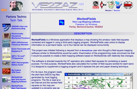 WorkedFields is a windows free software to displays a map showing the amateur radio field squares contacted and logged in using a third-party logging program.
 -
 Presents Eagle Stainless Tube & Fabrication as a certified distributor specializing in various tubing products essential for antenna construction and other amateur radio projects. It details their offerings, which include aluminum tubes in fractional, metric, and heavy wall specifications, alongside stainless steel bar stock in round, square, and flat profiles. The resource highlights the availability of a diameter sizing chart and direct contact options for specialists, indicating a focus on providing specific material dimensions and expert support for custom fabrication needs. The company emphasizes its role as a supplier of raw materials, crucial for hams engaged in DIY antenna builds or structural components for their shacks. Their inventory supports the precise mechanical requirements often encountered in radio frequency engineering, where material strength, weight, and corrosion resistance are critical design factors for outdoor installations. The site primarily serves as a product catalog and contact point for sourcing specialized metal tubing and bar stock, providing technical specifications and material grades relevant to robust amateur radio infrastructure.
 -
 Optimizing weak signal reception on the HF bands, particularly in the presence of strong local QRM, often necessitates specialized receiving antenna systems. This resource details the _HI-Z Antennas_ product line, focusing on phased vertical arrays designed for superior noise rejection and directivity. It covers components such as the 4-Square and 8-Element array controllers, which allow for rapid switching of receive patterns, and dedicated low-noise preamplifiers to improve system sensitivity. The site also presents various bandpass filters, crucial for mitigating out-of-band interference and enhancing the dynamic range of the receiver. The HI-Z systems are engineered to provide significant front-to-back and side rejection, often yielding **20-30 dB** of attenuation to unwanted signals, which is critical for DXing and contesting. Users can achieve a notable reduction in local noise, allowing for the discernment of signals that would otherwise be buried. The array controllers facilitate quick pattern changes, enabling operators to null out interference or peak weak signals from distant stations, effectively extending the reach of their receive capabilities by improving the signal-to-noise ratio.
 -
 Several bash scripts are provided to automate common amateur radio tasks on Linux and FreeBSD systems, addressing the need for quick access to specific data without navigating web interfaces. These utilities include `call` for fetching US callsign details from callook.info, `qth` for obtaining address information for US and Canadian callsigns, and `grid` for determining grid squares based on license addresses. Each script is designed for command-line execution, allowing for single lookups or interactive sessions, and emphasizes a KISS (Keep It Simple, Stupid) programming philosophy. Another script, `au_kp.sh`, is tailored for weak signal VHF operators, fetching and displaying the NOAA 30-minute Aurora forecast and GFZ Space Weather Kp index data. This script generates static images, requiring re-execution for updates, and is intended to be run as a clickable desktop object for real-time space weather monitoring. It helps operators track propagation conditions, especially during solar cycle peaks. Beyond bash scripts, the resource offers a PHP/web page `fortune` implementation, including Henrik Aasted Sorensen's PHP script, sample HTML/CSS, and a HOWTO guide for creating fortune files. W3DHJ provides several amateur radio-themed fortune files, such as "Ham Humor & Wisdom" with 354 entries and "VHF Rover Humor & Wisdom" with 223 entries, along with other general humor and wisdom collections. These fortune files are designed with embedded HTML for web page display and are refreshed monthly, offering a total of 21,400 entries.
 -
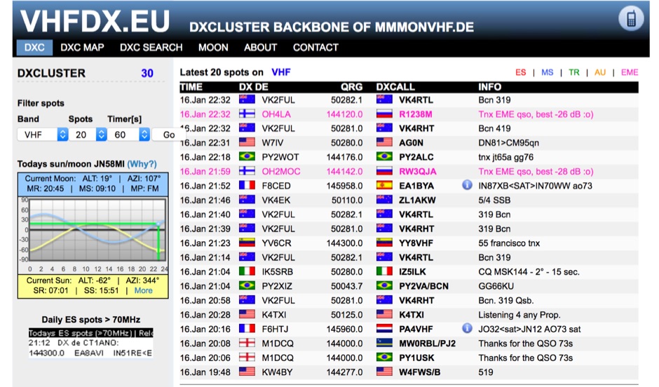 Presents the VHFDX.EU web cluster, a specialized resource for VHF, UHF, and microwave DX spotting. It details the cluster's functionality, including real-time spot aggregation and a DXCluster Map interface for visualizing activity. The resource highlights its integration with the MMMonVHF backbone, ensuring a robust data flow for monitoring band openings and propagation events across higher frequencies. It also references reviews of the ON4KST and N0UK chat systems, which are frequently used in conjunction with VHF DX operations. The platform offers a mobile-optimized view for on-the-go access to DX spots, catering to portable and mobile operators. It further provides daily ES (Sporadic E) spot summaries, a critical feature for VHF operators tracking this specific propagation mode. The cluster serves as a central point for operators to share and receive information on rare grid squares, contest activity, and general band conditions above 50 MHz.
 -
 The _Sci.Electronics FAQ: Repair: RFI/EMI Info_ document, authored by Daniel 9V1ZV, provides a detailed analysis of computer-generated RFI/EMI, focusing on its impact on radio reception. It identifies common RFI sources such as CPU clock rates (e.g., 4.77 MHz to 80 MHz), video card oscillators (e.g., 14.316 MHz), and even keyboard microprocessors, all of which generate square-wave harmonics across HF and L-VHF regions. The resource outlines a systematic procedure for pinpointing RFI origins, including disconnecting peripherals and using a portable AM/SW receiver with a ferrite rod antenna to localize strong interference sources. The document categorizes RFI mitigation into shielding, filtering, and design problems, offering practical solutions for each. It recommends applying conductive sprays like _EMI-LAC_ or _EMV-LACK_ to plastic casings of radios, monitors, and CPUs to create effective Faraday cages, emphasizing proper grounding and avoiding short circuits. For filtering, the guide suggests using line filters, ferrite beads, and toroids on power and data lines, and small value capacitors (e.g., 0.01 uF for serial/parallel, 100 pF for video) to shunt RFI to ground. It also discusses the use of bandpass, high-pass, low-pass, and notch filters on the receiver front-end or antenna feed to combat specific in-band noise.
 -
 The South Alabama Radio Club is located in Covington County, Alabama in grid square EM61
 -
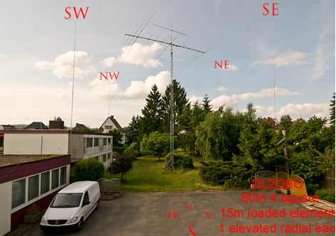 A project for a ground mounted 4 square antenna by DM9EE
 -
 This circuit is very simple and has a fantastic range of potential uses.
 -
 A synthesized 2.3 GHz Amateur Television (ATV) transmitter design, conceived by Ian G6TVJ, is presented, targeting broadcast-quality video performance on the 13cm band and extending up to 2.6 GHz. The core of the design utilizes a commercial Z-comm Voltage Controlled Oscillator (VCO) that tunes from 2.2-2.7 GHz, providing a +10 dBm output and simplifying RF alignment. This VCO's stability, originally intended for narrowband applications, readily accepts high-frequency video modulation, contributing to the transmitter's robust performance. The exciter stage, incorporating a Mini Circuits VNA 25 MMIC amplifier, boosts the signal to +16dBm, while a Plessey SP4982 prescaler divides the output frequency for the synthesizer. The synthesizer employs a Motorola MC145151 CMOS parallel IC, favored over the common Plessey SP5060 for its superior video modulation characteristics and ease of programming without microprocessors. This choice addresses issues like LF tilt and distorted field syncs often seen with SP5060 designs, particularly when operating through repeaters or over long distances. The MC145151 divides the signal further, enabling precise frequency stepping, with programming handled by EPROMs for channel selection and LED display. The loop filter network, critical for video integrity, was developed through experimentation to prevent the PLL from reacting to video modulation, ensuring a clean transmitted picture. The transmitter incorporates a Down East Microwave commercial power amplifier module, delivering approximately 1.6W output, driven by the exciter through a 3dB attenuator. Construction involves surface-mount SHF components on micro-strip lines etched onto double-sided fiberglass board, housed within a tinplate box. The design boasts no AC coupling in the video path, preserving low-frequency response, a common failing in other ATV transmitters. Performance tests with a 50Hz square wave revealed no LF distortion, and a calibrated "Pulse & Bar" signal showed a near 100% HF response, demonstrating its capability for high-quality ATV transmissions.
 -
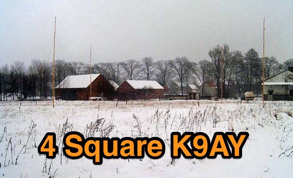 4 Square K9AY Array project for 80 and 40 meters band
 -
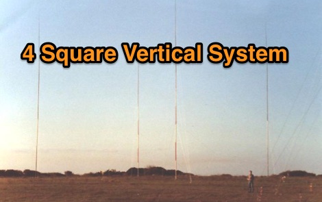 This page is a short description of the four phased verticals system for 160m 80m and 40m
 -
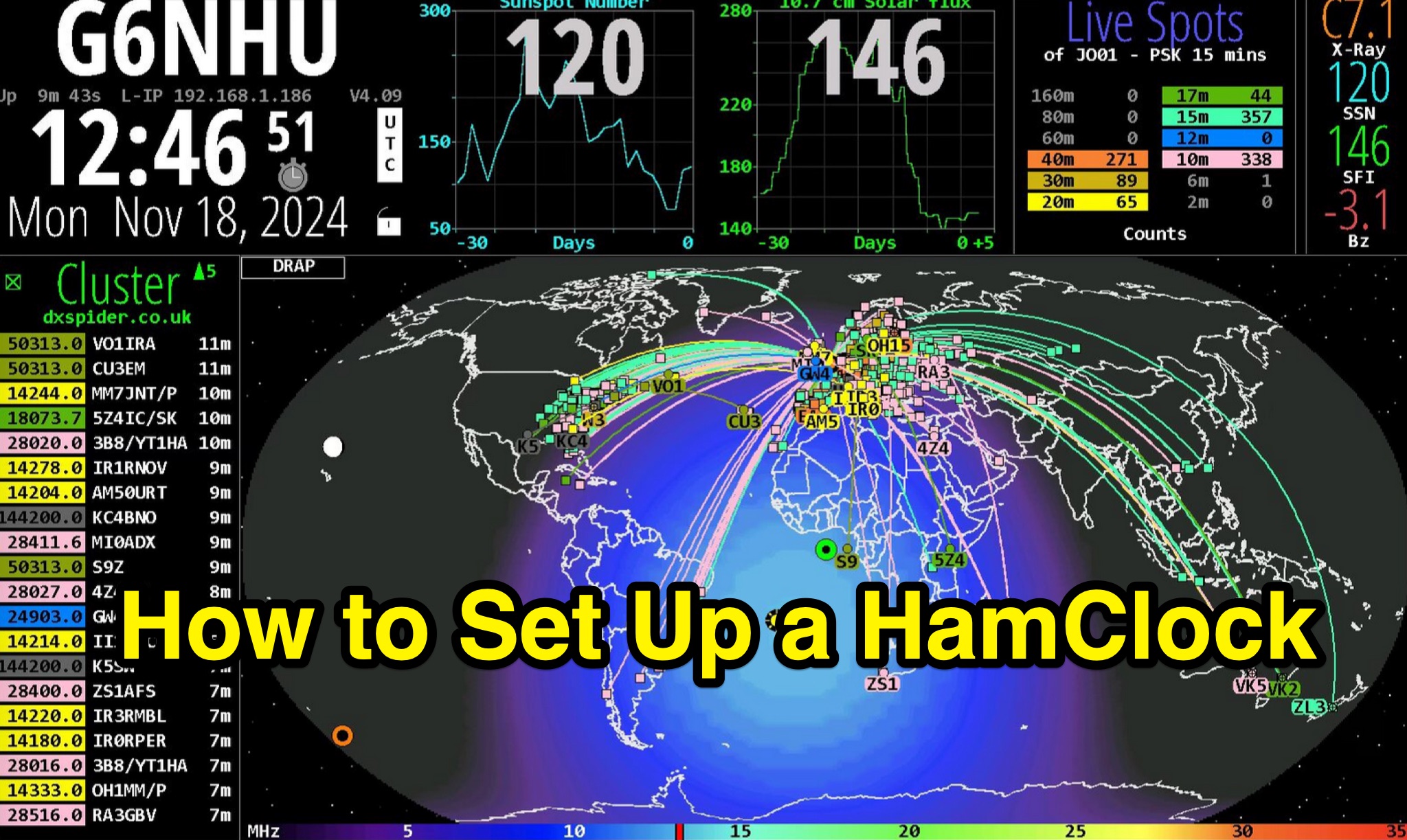 Demonstrates the complete process of setting up a _HamClock_ for an amateur radio shack, utilizing a Raspberry Pi and the HamClock 4.21 software. The guide meticulously covers hardware recommendations, including specific Raspberry Pi models like the Pi 4, suitable SD cards, power supplies, and display options. It provides step-by-step instructions for preparing the SD card with Raspberry Pi OS, performing initial system updates, and executing the HamClock installation script. Detailed configuration steps are outlined for HamClock's seven setup pages, addressing callsign, grid square, DX Cluster settings (e.g., `dxspider.co.uk` port **7300**), map centering, and crucial features like automatic space weather map rotation and auto-upgrades. The resource further explains how to customize HamClock's display panels, such as replacing default panels with a large DX Cluster display or a dedicated Space Weather panel. It illustrates configuring the Live Spots panel to show _PSKReporter_ data, filtering spots by grid square and time (e.g., **15 minutes**), and selecting specific bands for monitoring. The author, G6NHU, shares personal preferences for map types, recommending the DRAP style with Robinson projection for optimal amateur radio utility. Additionally, the guide provides specific DX Cluster filtering commands to manage spot overload, including methods to exclude data modes like FT8 and FT4, ensuring a cleaner display of relevant DX activity.
 -
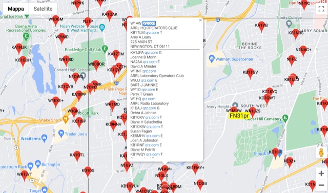 The resource provides an interactive map interface for locating amateur radio license holders across the United States. Users can input a _callsign_, _gridsquare_, zip code, or street address to center the map, which then dynamically populates with station markers. This functionality allows for precise geographical searches, revealing the distribution of hams within specific areas. Upon initial search, the map renders with adjustable zoom and pan capabilities. A key feature is its automatic reload mechanism: after two seconds of inactivity, the map updates to display stations within the newly viewed area. This ensures that the displayed data remains relevant to the user's current focus, whether exploring a densely populated urban center or a more remote region. Further interactive elements include clickable gridsquare labels, which re-center the map, and a "Show gridsquares" checkbox for toggling grid line visibility. Clicking on individual station markers reveals a popup containing the licensee's name and address information, making it a practical tool for geographical station identification.
 -
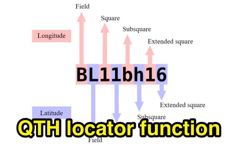 Python functions for converting decimal coordinates to QTH locator and backwards. Useful for program software developers to determine grid square locator, also known as maidenhead locator system.
 -
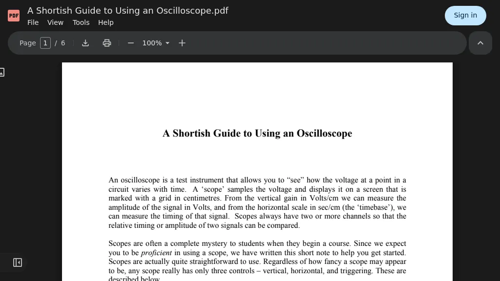 The "Shortish Guide to Using an Oscilloscope" elucidates the fundamental operation of oscilloscopes, detailing the purpose and function of vertical, horizontal, and triggering controls. It explains how vertical gain in Volts/cm and horizontal scale in sec/cm enable measurement of signal amplitude and timing, respectively. The resource differentiates between analog and digital scopes, noting that digital scopes often feature "soft" controls and are inherently storage scopes capable of capturing non-repetitive events. The guide dedicates a significant section to the critical role of oscilloscope probes, emphasizing their design to transmit waveforms without distortion or added noise. It explains the concept of a 10x passive scope probe, which reduces circuit loading by a factor of ten and eliminates waveform distortion through probe compensation, typically adjusted using a 1kHz square wave reference output. The document also provides practical advice on probe care and compensation procedures. Further sections address grounding considerations, explaining how a scope measures voltage relative to its chassis ground, which is tied to the protective earth. It offers troubleshooting steps for a blank screen and outlines essential good practices, such as checking input gain and probe attenuation, while explicitly warning against misusing probes or connecting the ground clip to mains voltage.
 -
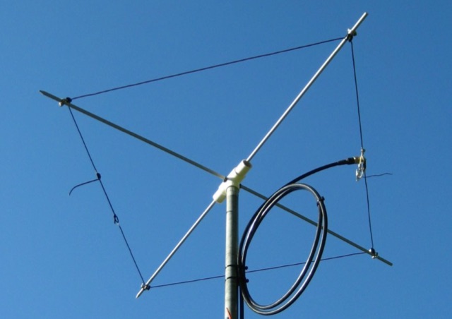 The antenna described in this article is for 50 MHz, but the design can be scaled for any band, including VHF, UHF, or even the higher HF bands. The antenna is nothing more than a square loop of wire, approximately 30" (or ~76cm) per side. The loop is fed in the middle of one side, and the opposite side to the feed point has a gap in it.
 -
 Presents an alternative construction method for isolated element Yagi antennas, specifically for VHF/UHF operation. The technique utilizes commercially available vibration damping clamps (resin support blocks) to isolate 1/4-inch aluminum rod elements from a 1-inch square aluminum boom, simplifying the build process by eliminating the need for custom-machined insulators. This approach is demonstrated through the construction of 6-element Optimized Wide-Band (OWA) Yagis for the 2-meter, 1.25-meter, and 70-centimeter bands, which are well-suited for portable contesting arrays due to their light weight and decent gain. The document provides detailed specifications for element and boom materials, along with step-by-step procedures for cutting, drilling, and tapping. It also covers the fabrication of a feedpoint bracket for a direct 50-ohm SO-239 coax connection and discusses considerations for horizontal versus vertical polarization, including mast placement. The resulting 6-element models achieve an average free-space gain of 10.2 dBi and a 25 dB front-to-back ratio, with the construction technique being scalable for higher gain designs. Included are parts lists with sources, detailed mechanical drawings for each band, and EZNEC data for the 2-meter and 70-centimeter designs, showing both free-space and 30-foot elevation performance. The designs are optimized from W4RNL's original concepts using HAMCALC, ensuring good gain, passband characteristics, and front-to-back ratios for wideband Yagi operation.
 -
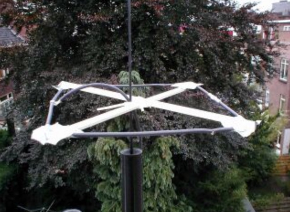 Sort of similar to the one of the 6m omni. Instead of using twin-lead, this design makes use of a more or less regular double bazooka antenna (coaxial dipole). Your attention shall be drawn to the available standart literature, such as Rothammel. In order to "compute" the dimension, Karl Rothammel mentioned that the total length of the dipole shall be 95% of the free-space wavelength. The short-circuit bridges (closing the folded dipole) are to be placed at a distance-fraction being equal to the velocity factor of the coax cable used, which will be 66% using RG-58 or RG174.
 -
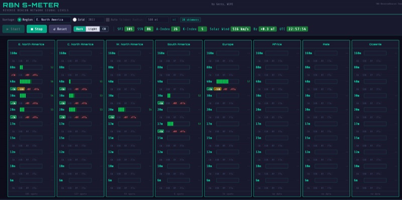 The RBN S-Meter visualizes real-time HF propagation data from the Reverse Beacon Network (RBN). It processes thousands of automated spots per hour, providing a real-time picture of active RF paths on HF bands. Users can set their vantage point using _Region Mode_ or _Grid Square Mode_. Region Mode allows selection from broad geographic areas like E. North America or Europe, while Grid Square Mode uses a Maidenhead grid square and radius for more precise data. The app displays eight region panels, each with horizontal bars for bands 160m through 6m, indicating signal strength with a color ramp from green to red. A dimmer trail shows peak hold values, and an S-unit readout provides additional detail. The app is a free web application accessible on any device, offering a practical tool for ham radio operators interested in CW, RTTY, and FT8 signals. It features a Progressive Web App installation option for enhanced usability on mobile and desktop platforms. Users can install it on Android, iOS, and Windows devices, providing a native app-like experience. The app replaces the previous Windows standalone executable, incorporating user feedback to improve features like grid square mode and automatic location detection.
 -
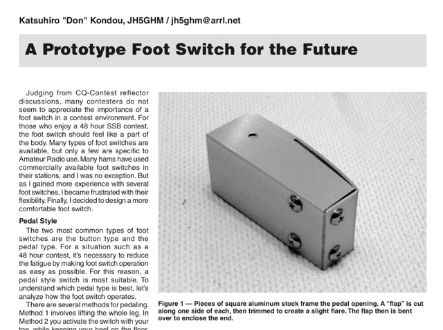 A prototype of a switch foot made on a square aluminium stock frame
 -
 Visual Wais is a free HAM (Amateur Radio) software to manage WAIS (Worked All Italian Squares) award. With few clicks, it allows the complete award management, from QSO insertion to endorsement requests.
 -
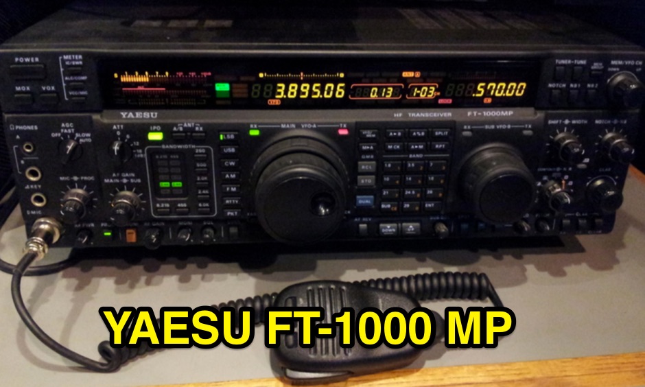 A page dedicated to Yaesu Mark V/FT-1000MP transceiver squarely aimed at the high performance contest and DX crowd.
 -
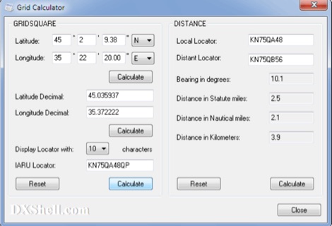 Grid Calculator allows you to calculate either a grid square locator or the latitude and longitude of a location. Grid Calculator can be used to calculate a Great Circle bearing and distance between two stations in statute miles, nautical miles, and kilometers.
 -
 Available worldwide can be used as Arduino Shield or plug it in to you PC , or with a bluetooth adapter connect to Android. With a highly optimized software, KAI200 brings you: a. Antenna analyzer form 1 up to 200 Mhz; b. WSPR transmiter (set up by serial terminal); c. Square Wave Signal generator KAI200 is all you need for your radio whatever it is Yaesu, Icom, Kenwood or Drake and DIY projects.
 -
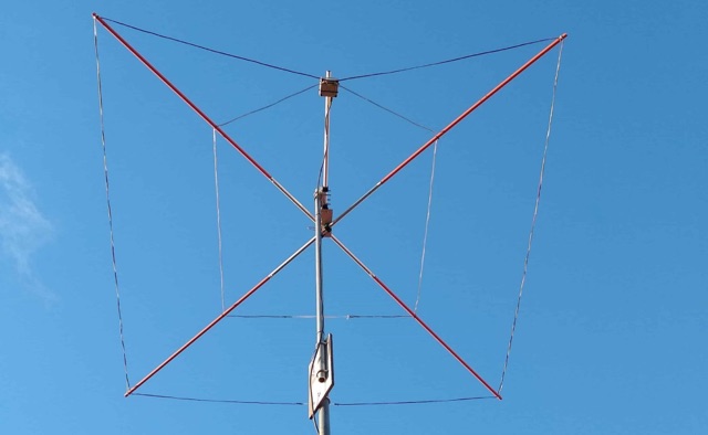 How to build a limited space 10 and 20 meter band Square Halo DX antenna. A horizontally polarized antenna for 10 and 20 meter band, which is suitable for a limited space.
 -
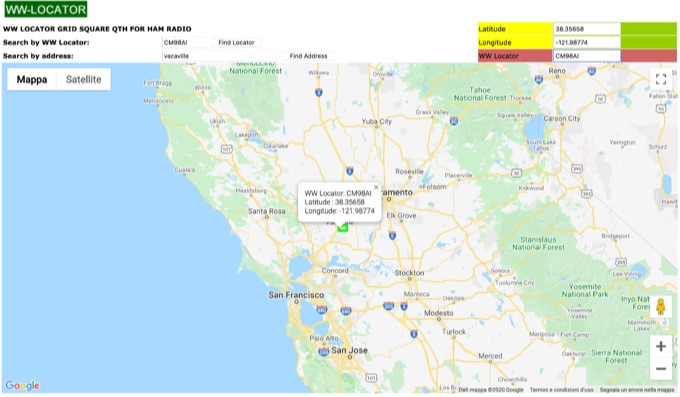 WW Locator grid square map and QTH locator made with google maps for ham radio