Search results
Query: 6 meters band
Links: 637 | Categories: 5
-
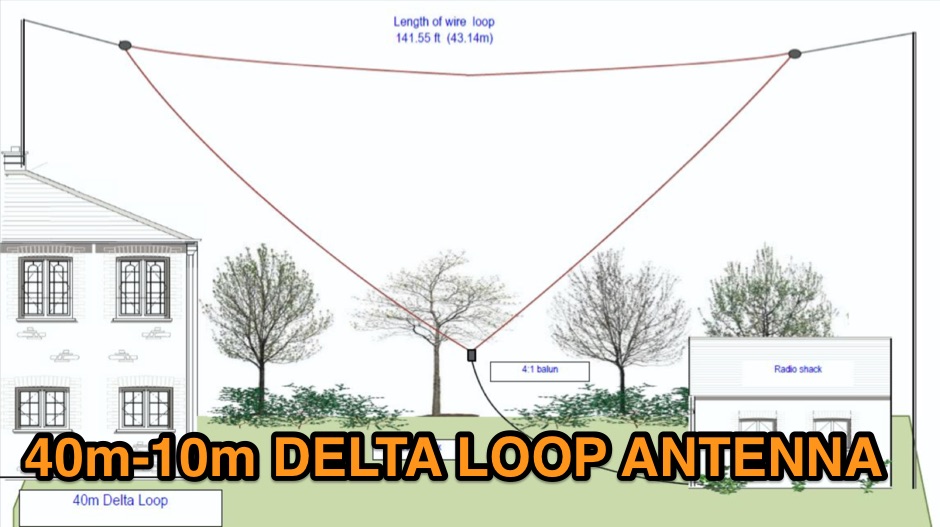 A multi band inverted delta loop antenna project that can be used from 40 to 10 meters band with full details and analysis of antenna performances on each band, document includes EZNec reports and setup pictures
 -
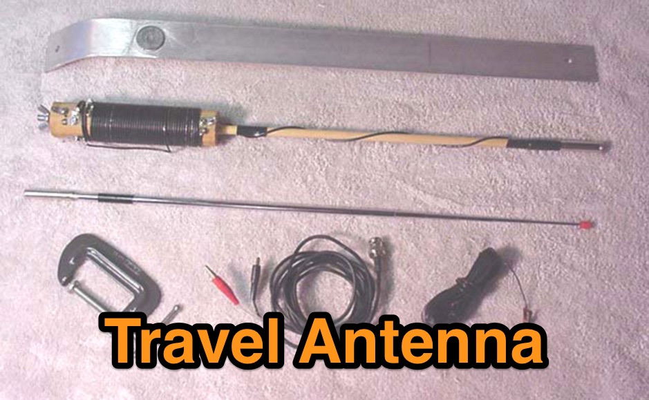 This is a low cost homebrew two band travel antenna for 20 and 40 meters. It is based on the B&W Travel Antenna concept with a telescoping whip and a loading coil
 -
 A switchable antenna for 80/160 meters by IK1ZOY. A new version of a 1/4L 80 m. dipole modified for use in 160 m. band. using it's own coaxial cable feeder to wrap a coil.
 -
-
 a simple, low-cost, trapless short vertical antenna which amazingly works on three HF bands (20, 15 and 10 meters)
 -
 10 meter modification for the Ameritron AL-811 and AL-811H amplifier. This mod apply to other Ameritron AL Series RF amplifiers and allow extension to 10 and 12 meters band.
 -
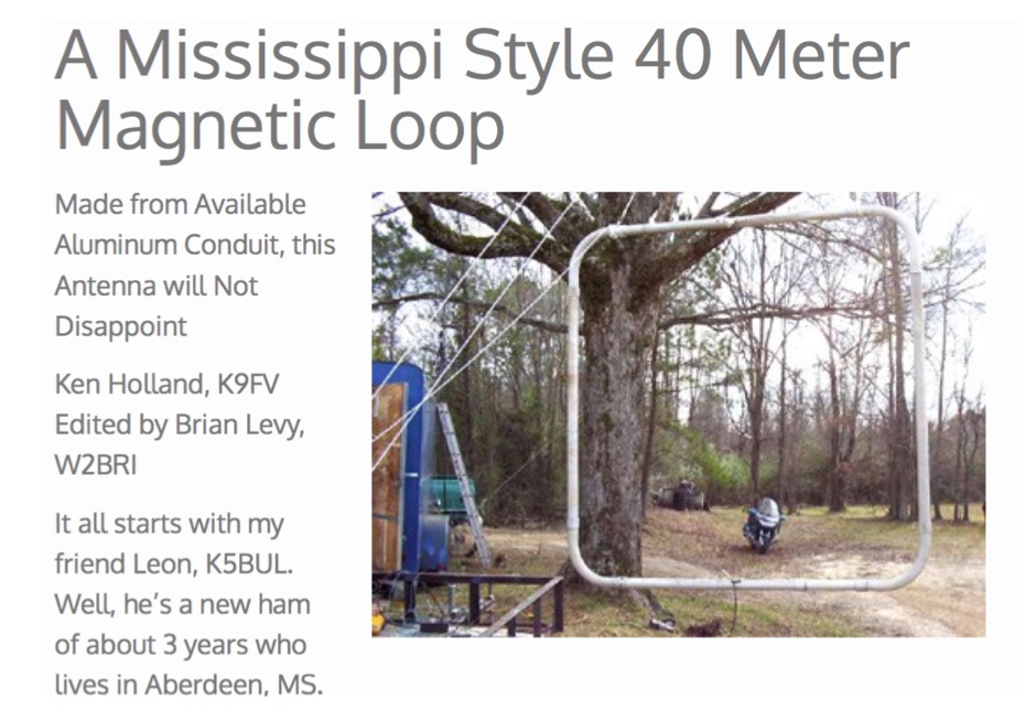 A Mississippi Style 40 meter magnetic loop made from available aluminum conduit, this antenna will not disappoint by Ken Holland, K9FV
 -
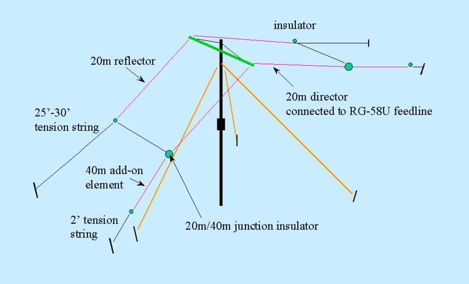 A wire yagi antenna for 20 and 40 meters band suitable for outdoor and field day operations
 -
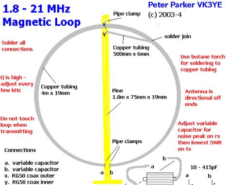 Magnetic loops are a compromise antenna and performance will be down on a full size-wire antenna particurlarly on lower HF Bands. This article compare this magnetic loop with a full-sized wire antenna on 80 meters by VK3YE
 -
 Presents the KE4UYP linear-loaded vertical antenna design, which introduces very little loss on 80 or 160 meters, achieving an overall radiation efficiency of 80% to 85%. This design addresses common pitfalls of traditional base-fed verticals by placing the majority of the current at the top of the antenna, eliminating the heavy reliance on extensive ground radial systems. The author's initial 10-meter model, only three feet tall, yielded 5/9 signal reports to Anchorage, AK, and Europe, confirming its effectiveness. The antenna incorporates both vertically and horizontally polarized radiators, with a 1/4 wavelength horizontal counterpoise located at the feed-point, near the top, to create an almost totally omnidirectional pattern with high wave angle horizontally polarized radiation. This dual polarization ensures even illumination across all take-off angles, making it effective for both local contacts and **DXing**. The vertical element is linear loaded, adding capacitance reactance and making it longer than the horizontal element to achieve resonance and raise the feed-point impedance to 50 ohms. Fine-tuning the antenna requires careful adjustment, as tower reactance can vary. The article suggests starting with 80 feet for 80m and 170 feet for 160m for the vertical wire, then trimming for resonance. Bandwidth specifications include 300 kHz under 2:1 **SWR** on 80m and 100 kHz on 160m when suspended between trees, or 150 kHz on 80m when side-mounted on a tower.
 -
 Version 7.22 of XMLog provides a fix for an issue where the ARRL LoTW application TQSL produced error messages concerning invalid "MY-COUNTRY" values, ensuring smoother integration for award submissions. The software supports flexible log searching, allowing users to select log subsets based on any field, such as RTTY QSOs on 40 meters during a specific month, or entries for a single country with sent but unreceived QSLs. XMLog tracks DXCC, WAZ, WAS, county hunting, IOTA, and grid square awards, managing QSL sent/received status and submission status to award sponsors, with LoTW crediting for DXCC and WAS. It generates detailed reports summarizing QSL status by band and mode, identifying needed countries/states/zones, and listing critical QSOs that could boost award totals. The system also integrates with callbook services like QRZ.com (subscription required) and WM7D.net for lookups, and facilitates QSL and mailing label printing using standard or custom layouts. Further capabilities include ADIF, Excel, and CSV log import/export, a Packet Window for Internet PacketCluster nodes or TNCs with history and scripting, and vocal/CW alerts for needed QSOs based on PacketCluster spots. Rig control is supported for a wide array of Alinco, Elecraft, Flex, Heath, Icom, JRC, Kenwood, TenTec, and Yaesu transceivers, enabling frequency/mode synchronization and control. CW support is provided via a serial port interface compatible with N1MM or K1EL WinKeyer, allowing CW sending from a keyboard or pre-programmed messages.
 -
 The Flower Pot Antenna project details a portable dual-band antenna primarily operating on 10 meters, with secondary resonance near the 30-meter band. Construction involves winding RG58 coaxial cable uniformly around a large plastic flower pot, approximately 70cm high with a 60cm top diameter. The design eliminates the need for radials, contributing to its compact and lightweight nature. Key construction steps include soldering the inner conductor to the shield at one end of the wound cable and connecting the wound cable's shield to the rig cable's inner conductor at the base. An LC network, comprising a variable capacitor (0-200pF) and an inductor (10 coils, 5cm diameter, 2mm wire), is inserted between the wound cable's inner conductor and the rig cable's shield. Tuning is performed with an antenna analyzer, adjusting cable length and the variable capacitor for optimal impedance on 10 meters. The antenna performs effectively when installed horizontally.
 -
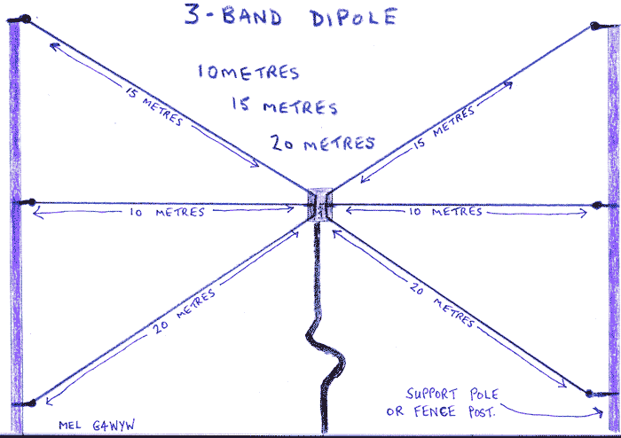 A 3 band dipole for 10 15 and 20 meters band, easy to build, and that can be easily setup in any occasion, inclunding field days or portable operations
 -
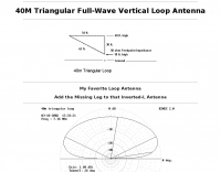 A 40 meters band full wave antenna project plan with model, adding the Missing Leg to the Inverted-L Antenna
 -
-
 Experimental omni-directional antennas for 6-meters band
 -
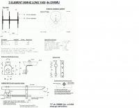 A 3 elements long yagi antenna for 6 meters band by ON6MU
 -
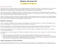 This antenna is not a true Windom, but rather an off center fed or OCF dipole works on 8 bands from 80 to 10 meters
 -
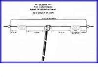 A coil loaded dipole antenna for 40 and 80 meters band by I2CN
 -
 Demonstrates adapting the _Moxon rectangle_ antenna design for 2-meter VHF operation, highlighting its unique characteristics for specific applications. It details how the antenna's small size and distinctive far-field pattern, typically associated with HF, can be effectively utilized on VHF. The resource provides modeled dimensions for three different element diameters (1/4", 1/2", 1") and discusses the necessary adjustments to maintain optimal performance, such as gap spacing and element lengths, to achieve a 50-Ohm feedpoint impedance. The article presents predicted performance data, including gain (dBi), front-to-back ratio (dB), and feedpoint impedance (R, jX) across 144, 146, and 148 MHz. It analyzes free-space azimuth patterns and discusses the antenna's behavior when horizontally and vertically polarized over ground, including its suitability for fixed installations, repeater applications, and even satellite communications. Construction considerations, such as bending elements and maintaining critical gap distances, are also addressed. Furthermore, the content explores advanced configurations like using two back-to-back rectangles for broader coverage and a crossed-Moxon setup for circular polarization, suggesting potential for urban communication and satellite work. The author, _L. B. Cebik, W4RNL_, emphasizes the Moxon's strengths in broad bandwidth, wide beamwidth, and high front-to-back ratio, rather than maximum gain.
 -
 A 3 Element Mono-band Yagi for 20 meters by Kees Wiegers, PA5CW (ex-PA3BHS)
 -
 A **mobile HF multiband antenna** project details the construction of a center and top-loaded design, optimized for 10 through 80 meters. This antenna incorporates a capacity hat positioned high on the whip for enhanced efficiency, differing from commercial bugcatcher designs. The coil construction prioritizes high Q and minimal loss through an air core, open spacing, and heavy gauge wire, contributing to its lightweight nature and suitability for portable operation with a proper counterpoise. Band switching is achieved by manually moving a jumper plug to various tap points on the coil, allowing for operation across multiple bands, with 17m being resonant when the coil is bypassed. The design, a result of nine months of experimentation by N1LO, includes detailed instructions for modifying a Hamstick antenna base, creating a jumper wire, and assembling the capacity hat using stainless steel wire and silver-bearing solder for robust connections. The loading coil utilizes nylon grommet strips around a PVC pipe for an air-core winding, ensuring high efficiency. Tap sockets are fashioned from silver-plated 5-way binding posts, providing low-resistance RF joints for band selection. Guidance on tap point determination emphasizes using an antenna analyzer like the MFJ 259B or 269 to achieve resonance, especially on 40m and 80m where feedpoint resistance can be low. The document also covers the installation of monofilament stays to maintain antenna uprightness at highway speeds, with specific attachment points for stability.
 -
 HF multiband mini delta compact and easy assembling antenna that cover from 20 to 10 meters by GM3VLB
 -
 The _Morgain_ antenna for 40/80 meters is a straightforward and cost-effective wire antenna design, requiring careful tuning for optimal performance across two bands with low SWR. Construction involves creating 12 cm PVC spacers with three holes for wire insertion, along with larger terminals for anchoring and connector housing, which should be sealed with silicone. The provided measurements detail the specific lengths for the antenna elements, crucial for achieving resonance on both 40m and 80m bands. Tuning the Morgain antenna necessitates fabricating four wire segments with pins to temporarily connect and adjust the bridging points symmetrically for both 40m and 80m. This iterative process, though time-consuming, ensures the antenna functions effectively for decades once the precise connection points are soldered and protected. The design emphasizes ease of construction and long-term stability, making it a practical solution for hams seeking a dual-band wire antenna.
 -
-
-
 A solid state amplifier for HF and 6 meters band by N4IP
 -
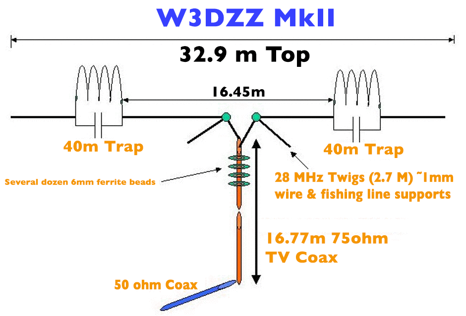 The multi-band trapped dipole is resonant on approx 3.7, 7, 14, 24 7 28.5 Mhz. The overall top length needs to be approximately 32.9 Meters
 -
 The article details the construction of a "bug-catcher" style HF mobile antenna, emphasizing its low cost and ease of tuning. It outlines the use of readily available materials such as PVC pipe, #14 house wire for loading and matching coils, and a _RadioShack_ replacement whip antenna. The design allows for operation across 20 through 6 meters, achieving an SWR of **1.5:1** or less on each band segment. The resource provides a comprehensive materials list, step-by-step assembly instructions, and photographs illustrating key construction phases. It explains how to create the coil forms, wind the coils, and secure them with epoxy putty. Crucially, the guide includes a table of suggested coil-tap positions and whip extensions for specific bands, such as 6 turns on the matching coil and 8 turns on the loading coil for 20 meters, facilitating initial tuning. Furthermore, the document discusses installation considerations, including grounding, and offers practical advice for tuning the antenna using an SWR meter. It highlights the antenna's broadband characteristics and its ability to collapse the whip for garage storage, making it a practical solution for mobile HF operation. The author, KM4IE, shares personal experiences with worldwide CW and phone contacts using this antenna.
 -
 Even if using a tuner this multiband antenna will let you operate from 160 to 10 meters. If you could only put up one antenna, this would be it. Project by N0KHQ.
 -
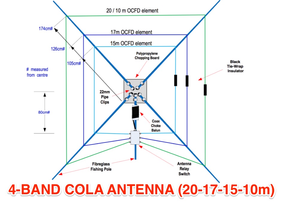 Concentric Open Loop Antenna Fed Off-Centre similar to the cobwebb antenna but resonating on 20-17-15-10 meters band
 -
 Moxon antenna for 50 MHz, The Moxon rectangle is a quite broad-band antenna, but it is not quite broad enough to cover the entire band.
 -
 40 meters band Delta loop antenna plan that is vertically polarised
 -
-
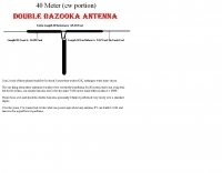 A double bazooka antenna plan for the cw portion of the 40 meter band
 -
 Demonstrates the construction and on-air performance of the _NB6Zep_ antenna, a modified 20-meter Extended Double Zepp design optimized for multi-band operation from 40 through 10 meters. The resource covers basic design principles, including dimensions of 66 feet horizontal and 5 feet vertical elements, and specifies open ladder line or TV twin lead for the transmission line. It details material selection for low-cost wire antenna construction, such as 18 AWG wire for the legs and ceramic or plastic insulators, along with practical tips for soldering connections and insulating against moisture. The author, NB6Z, shares insights from extensive _EZNEC_ modeling to optimize the antenna's total length for a 40-meter half-wave dipole footprint and feed line length for direct tuner connection. The article presents field results, including successful _PSK31_ contacts from Oregon to the East Coast on 40 and 30 meters with 50 watts, even at a low height of 6 feet. It provides detailed performance characteristics for each band, noting the _NB6Zep_'s highest gain (over 3 dB) and sharp, medium-angle lobes on 20 meters, which yielded strong DX reports to locations like Korea, Japan, and Argentina. For 17 and 15 meters, it describes a butterfly-like pattern with broad lobes, while 12 and 10 meters exhibit narrow, directional lobes in an "X" configuration. The author also shares personal experiences operating successfully for over a decade in an antenna-restricted environment using the NB6Zep and other stealth wire antennas.
 -
 An easy to build Hexbeam antenna built with bamboo sticks for the six meters band
 -
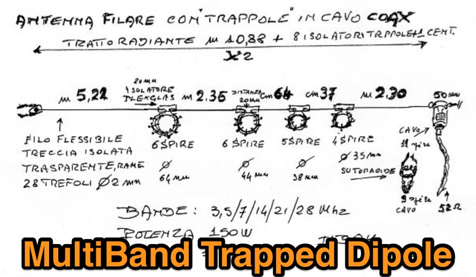 This multiband antenna 10-80 meters is a home made project by I1BAY. Has been used for SOTA activations with great results. Traps are done with coax cable turns, dimensions are in the attached schema.
 -
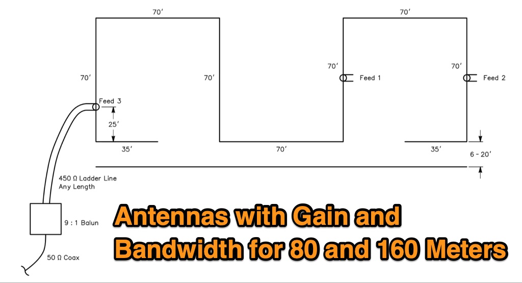 The Bruce array is a simple, often-forgotten wire antenna array that is advantageous for 80 and 160 meters, where typical gain antennas are very large. This bi-directional broadside vertical array is only 1\4 lambda high and does not require a ground system. It offers substantially greater SWR bandwidth than the half-square or bobtail curtain. A 4-element Bruce array used by N6LF showed a gain of about 4.6 dB compared to a 1\4 lambda vertical with 8 elevated radials, with a 2:1 SWR bandwidth greater than 400 kHz. The antenna is simple and its dimensions are flexible.
 -
-
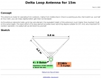 Delta Loop Antenna for 15m band. This antenna is made for operating from outdoors, mainly from mobile shack. Drive to a parking you like, then build it up. Just half an hour later, you can enjoy slightly better gain than normal dipole.
 -
 Presents a catalog of **QRP** transceivers, antenna tuners, and related accessories for amateur radio operators. The product line includes the ZM-2 antenna tuner, designed for efficient impedance matching across HF bands, and the NW-series QRP transceivers, offering low-power CW operation. Additionally, the site details various ladder line insulators and specialized connectors, emphasizing robust construction for field deployment and home station use. Each product listing provides specifications, operational parameters, and pricing information. Compares the features of different **QRP transceiver** models, such as the NW-40 and NW-20, highlighting their respective band coverage and power output capabilities. The ZM-2 tuner's performance is detailed with typical SWR reduction figures for various antenna types, demonstrating its utility for portable and fixed stations. Customer testimonials and product images illustrate the practical application and build quality of EMTECH's offerings, providing insights into their durability and ease of integration into existing amateur radio setups.
 -
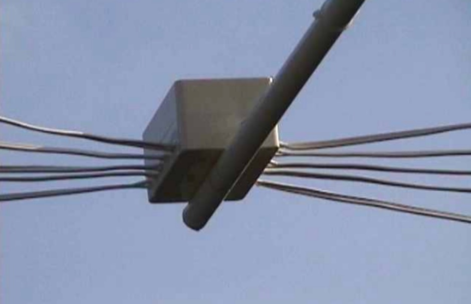 The cobweb antenna it is basically a 5 band antenna comprising of 5 full half wave dipoles for each band - between 10 meters and 20 meters, the antenna is also resonant on 6M and can be modeled even for VHF frequencies.
 -
 A bazooka antenna project for the 7 Mhz, includes dimension for to homebrew your own bazooka for HF bands
 -
 The article provides detailed instructions on how to build a half-sloper antenna for the 160 meters band. It explains the concept of a sloper antenna and how it differs from a slooper. The article includes practical tips on the construction and installation of the antenna to ensure optimal performance. The intended audience is amateur radio operators interested in building their own antenna for the 160 meters band. The content is informative, practical, and focused on DIY antenna building.
 -
 Presents a crystal-controlled CW transmitter design for the 40-meter band, delivering 5 to 7.5 watts output power. The circuit innovatively employs an _IRF510_ power MOSFET in the final amplifier stage, diverging from conventional bipolar transistors. This design offers high gain, nearly 90% efficiency, and robust resistance to high SWR, allowing 30-second key-down operation into an open circuit without damage. A critical aspect is the precise adjustment of the MOSFET gate bias via a 10K trimmer pot, _R10_, to maintain quiescent current between 5 and 10 mA, preventing thermal runaway inherent to bipolar devices. The prototype was constructed on a _Radio Shack universal board_ and achieved immediate operational success. The design requires a 15-volt Zener diode to protect the MOSFET gate from overvoltage. Component sourcing information is provided, including specific crystal frequencies (7.040 MHz or 7.122 MHz) available from _Dan’s Small Parts & Kits_ or Doug Hendricks. The fixed frequency can be slightly adjusted with a trimmer capacitor. A complete bill of materials, including resistor values, capacitor types, toroid specifications, and transistor part numbers, is detailed, alongside a clear schematic diagram.
 -
 5 Elem. yagi for 10 meters, 9 element yagi beam antenna for six meters band by ON4ANT
 -
 Presents a detailed construction guide for a 2-element _Moxon rectangle_ antenna optimized for the 10-meter band, designed by L. B. Cebik, W4RNL (SK). This resource demonstrates how to build a compact beam antenna using readily available hardware store aluminum tubing, fitting within a 12-13 foot width. It highlights the antenna's performance characteristics, including a gain comparable to a 2-element Yagi (11+ dBi) and a front-to-back ratio exceeding 20 dB between 28.3 and 28.5 MHz, with an SWR below 2:1 across the entire band. The design emphasizes direct 50-ohm coax connection without a separate matching system, though a 1:1 choke _balun_ is recommended. The guide provides practical advice on element construction, corner fabrication using L-stock or radius-bent tubing, and the critical side-to-side length adjustment for SWR optimization. It details the feedpoint assembly using a chassis-mounting coax connector and discusses element-to-boom plate options, including spar varnished plywood or LE plastic. The author's experience with a test model on a 20-foot mast confirms stable feedpoint characteristics and excellent performance even at lower heights. The document also includes insights into the antenna's free-space azimuth patterns, noting a broad forward lobe and significant front-to-back rejection. It contrasts the Moxon with traditional Yagis, positioning it as an effective, home-buildable alternative for compact sites or _Field Day_ operations, particularly beneficial during periods of increased 10-meter activity.
 -
 Manual for R7, 10 12 15 16 20 30 40 meters band antenna
 -
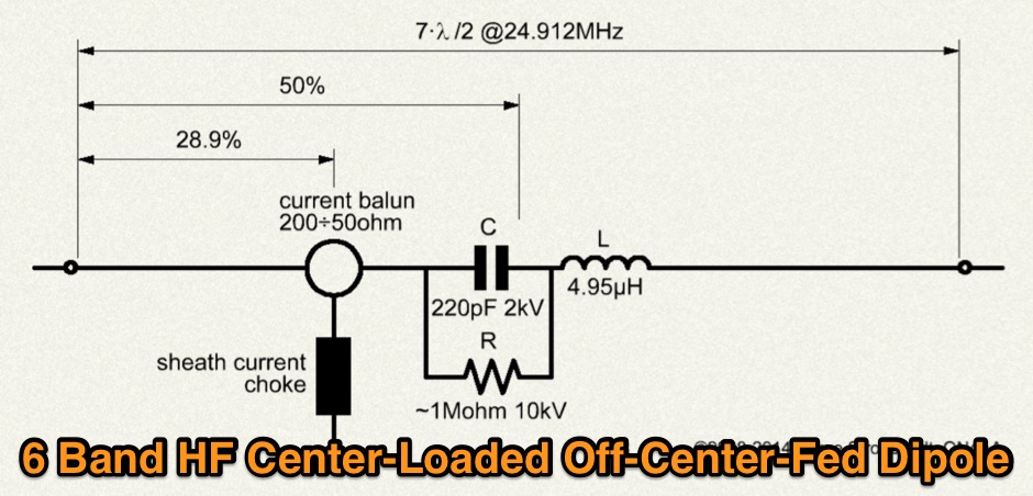 Multiband Center-Loaded Off-Center-Fed Dipole (CL-OCFD) antenna that work on 80m 40m 30m 20m 15m 10m. The Center-Loaded Off-Center-Fed Dipole (CL-OCFD) antenna, developed by Serge Stroobandt, offers a versatile solution for amateur radio enthusiasts, covering multiple HF bands (80, 40, 30, 20, 15, and 10 meters) without the need for an antenna tuner. This innovative design utilizes a capacitor for resonance on the 80-meter band and a resistor to manage static charges. The CL-OCFD enhances bandwidth and simplifies operation, making it a significant advancement on OCF Dipole design.