Search results
Query: add an s meter
Links: 166 | Categories: 0
-
 Presents the detailed construction of the _FLA25HV_ antenna, a specialized array optimized for Earth-Moon-Earth (EME) communications on the 2-meter band. This resource provides schematics and practical insights into building a high-gain antenna system capable of reflecting signals off the lunar surface, a challenging but rewarding aspect of amateur radio. It covers the mechanical and electrical considerations essential for achieving the precise pointing and signal strength required for successful moonbounce contacts, often yielding **20 dB** or more gain. Amateur radio operators pursuing EME operations require robust antenna systems and precise tracking capabilities. The FLA25HV design addresses these needs by focusing on element spacing, impedance matching, and structural integrity to withstand environmental factors while maintaining critical alignment for lunar reflections. Such systems are crucial for making contacts over distances exceeding **768,000 km**. This personal page serves as a practical guide for hams interested in constructing their own EME arrays, offering a glimpse into the technical dedication involved in pushing the boundaries of VHF/UHF propagation.
 -
 Demonstrates the essential steps for winding **toroidal cores**, a fundamental skill for amateur radio operators engaged in homebrewing and kit building. It addresses the critical aspects of selecting the correct core material and wire gauge, emphasizing the importance of precise turn counting and consistent winding tension to ensure optimal circuit performance. The resource details methods for preparing the wire, including techniques for safely removing enamel insulation from leads using flame, sandpaper, or a solder pot, and provides guidance on tinning the exposed wire. Explains the process of mounting the wound toroid onto a printed circuit board, highlighting the need for careful lead placement and secure soldering to prevent shorts and ensure mechanical stability. It also offers a practical formula for calculating the required wire length based on the desired number of turns and the specific **toroid** size, referencing common core types like T-50 and FT-240. The guide stresses the importance of verifying the inductance of the wound component, often using an inductance meter, to confirm it matches design specifications. Provides practical tips for handling multi-filar windings and managing short lead lengths, which can be particularly challenging. It underscores the necessity of meticulous attention to detail throughout the winding and installation process to achieve reliable and efficient RF circuits.
 -
 Operating a ZS6BKW antenna often involves understanding its lineage from the _G5RV_ design, with specific modifications by ZS6BKW to optimize performance on several bands. Through computational analysis and field measurements, the antenna's dimensions were refined to allow operation on 10, 12, 17, 20, and 40 meters without an antenna tuner. For 80, 30, and 15 meters, a tuner is necessary, though efficiency on 30 and 15 meters is noted as not particularly high. The physical configuration consists of two 13.755-meter radiating elements fed by a 12.20-meter section of 450-ohm ladder line. Tuning the antenna on the 20-meter band is critical, and any deviation in the ladder line's characteristic impedance necessitates recalculating the element lengths. The design is also referenced in the 12th edition of _Rothammel's Antennenbuch_, page 219. Proper common mode current suppression is crucial at the transition from ladder line to coaxial cable. This can be achieved with a common mode choke, such as several turns of coax wound into a coil or over a ferrite toroid like an Amidon T130. While a 1:1 balun is an option, it may introduce issues.
 -
 Operational testing of a 10.07-meter portable HF vertical antenna, constructed from telescoping aluminum tubing (36, 32, 22, 17 mm diameters), yielded SWR measurements below 1.5 across multiple bands. Initial trials on 14.150 MHz showed an SWR of 1.6, while 7.075 MHz was problematic. Subsequent adjustments, including a 13 cm extension to the radiating element, improved performance, enabling operation on 6, 15, and 40 meters without a balun, and adding 12 meters with a balun. The design prioritizes portability, allowing transport in a standard vehicle and single-person deployment. Four 10.07-meter radials are connected at the base to enhance ground plane effectiveness. The article details the mechanical assembly, including custom adapters for tube transitions and a PVC sanitary tube sleeve for base insulation, ensuring robust field deployment. Final SWR measurements, documented with an _MFJ-259_ antenna analyzer, confirm operational ranges: 6.800-7.500 MHz (SWR < 1.5), 20.800-22.500 MHz (SWR < 1.5), and 48.800-51.500 MHz (SWR < 1.5) without a balun. With a balun, the antenna achieved SWR < 1.5 on 13.750-15.000 MHz and 24.890-28.350 MHz, demonstrating its versatility for portable _DXpeditions_.
 -
 One specific challenge in the KazShack, operating Single Operator Two Radios (SO2R), involved sharing a K9AY receive antenna between two transceivers without direct RF connection or manual feedline swapping. The solution, detailed in this project, adapts the **W3LPL RX bandpass filter** design to split 160m and 80m signals, feeding them to separate radio inputs while maintaining isolation. This approach also addresses the issue of strong broadcast band interference from a nearby 50KW WPTF transmitter on 680kc. The construction utilizes T-50-3 toroids and NP0 ceramic capacitors, built in a "dead bug" style on copper clad board. Each band's filter coils are identical and resonated to the desired frequency using an MFJ-259 antenna analyzer. A single DPDT relay, controlled by a remote toggle switch mounted on an aluminum panel, facilitates quick band switching between radios, simplifying low-band operations. While some signal loss is noted, the expected lower noise levels from the receive antenna are anticipated to compensate, potentially reducing the need for constant volume adjustments during toggling between transmit and receive antennas.
 -
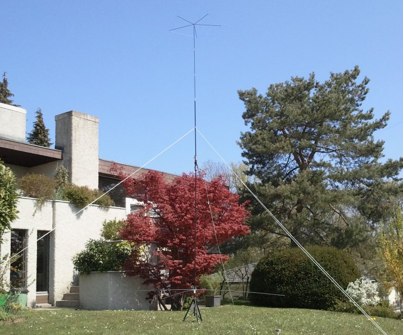 A vertical dipole for the 40 meters band made by using some buddipole parts and adding capacities on both ends by HB9MTN
 -
 The ZS6BKW antenna, a popular multiband wire antenna, offers improved band matching compared to the traditional G5RV. This construction guide details the process, beginning with specific dimensions: 13.11 meters (43 feet) for the 450-ohm ladder line and initial dipole arm lengths of approximately 14.8 meters each. It emphasizes the critical role of an _antenna analyzer_ for accurate tuning, particularly for determining the velocity factor of the ladder line and achieving a 1:1 impedance match. The article outlines the materials required, including a 1:1 current balun, 450-ohm window line, wire for the dipole arms, and a 50-ohm non-inductive resistor for testing. It provides a step-by-step procedure for cutting the ladder line to its electrical half-wavelength, explaining how to calculate the velocity factor using measured and free-space frequencies. For instance, a measured 50-ohm impedance at 12.54 MHz with a calculated free-space half-wavelength frequency of 11.44 MHz yields a velocity factor of 0.91. Final adjustments involve hoisting the antenna to its operational height and fine-tuning the dipole arm lengths to achieve optimal SWR, specifically targeting 14.200 MHz. The _ZS6BKW_ design is noted for its performance on 80m, 40m, 20m, 10m, and 6m, though it is not optimized for 15m operation. The author, _VK4MDX_, shares practical tips for durable construction using stainless steel wire and cable clamps.
 -
 The W4NFR 40-meter mobile vertical antenna project details the construction of a mobile antenna system, drawing inspiration from a July 2011 QST article by VE6AB. The design simplifies the top hat by integrating an 8-spoke top hat from Tar Heel Antenna. The resource outlines the tuning process, which involves adjusting the L1 coil for the desired band segment and then fine-tuning SWR with an L2 coil at the feed point. The author achieved a 1:1 SWR at 7.150 MHz with this configuration. The project includes specific instructions for adding anti-sway supports to ensure stable operation and reduce physical stress on the ball mount during vehicle motion. Visual aids such as drawings of the 40-meter mobile antenna, detailed views of the coil and top hat assembly, and an illustration of the ball and spring mount are provided to guide the builder through the construction and installation phases. The content focuses on practical implementation and tuning for optimal performance on the 40-meter band.
 -
 GW4ALG's _136 kHz Pages_ document the evolution of vertical antennas for the 2200m band, starting with a prototype mounted on a house wall. This initial design, despite achieving the first **395 km** GM-GW QSO, suffered from significant insulation breakdown, high RF losses due to proximity to the house, and difficult tuning adjustments. The author details the challenges of maintaining resonance and matching with a variometer in the loft, noting that adding three earth spikes offered no measurable improvement over a simple water tap connection. The subsequent experimental 12m vertical, relocated away from the house, significantly reduced dielectric losses and proved far more effective. This antenna enabled GW4ALG to set a world DX record on 136 kHz with a **1916 km** QSO to OH1TN, and an intra-UK record of **703 km** to GM3YXM/P. The resource further explores the use of helium-filled balloons to extend the vertical radiator, achieving heights up to 27m, typically 20m, for enhanced low-band performance. Practical advice on balloon types, inflation, and critical insulation between the wire and balloon is provided, emphasizing safety and avoiding arcing.
 -
 DK7ZB provides detailed construction plans for Moxon antennas utilizing tapered aluminum tubing, specifically outlining dimensions for 50 MHz, 28 MHz, 24 MHz, and 21 MHz bands. The resource emphasizes maintaining specific taper lengths for optimal performance and describes a tuning method involving symmetrical element shifts. It also addresses stacking considerations, noting that two Moxons can be stacked 1m apart with a 90° rotation to avoid severe detuning, unlike co-planar mounting. Performance figures for the 50-MHz Moxon include a gain of **4.1 dBd** and a front-to-back ratio of _30 dB_. The construction utilizes copper fittings for element connections, with a recommendation to varnish edges against corrosion. The page features images of built antennas by _DK8UH_ and VK2QO, illustrating practical implementations for the 6-meter and 10-meter bands, respectively.
 -
 The document provides a detailed guide on modifying an inverted-L antenna to include the 160 meters band. This enhancement allows amateur radio operators to utilize the lower frequency effectively, which is crucial for long-distance communication, especially during the night. The inverted-L design is popular due to its compact size and ease of installation, making it suitable for various environments. By adding top band capabilities, operators can engage in DXing and contesting on 160m, expanding their operational range and opportunities. The guide includes practical tips and considerations for construction, ensuring that the antenna maintains its performance across the extended frequency range. It discusses the necessary adjustments and materials required for the modification, along with potential challenges and solutions. Whether you are a seasoned operator or a beginner, this project can enhance your station's capabilities, allowing for more versatile operations and improved signal quality on the 160m band.
 -
 Codec2, an open-source speech codec, targets low bit rate voice communication, specifically designed for digital radio applications operating within constrained bandwidths. The project focuses on achieving intelligible speech quality at data rates around 2400 bits per second, a critical parameter for efficient spectrum utilization in amateur radio. Its development addresses the need for robust voice transmission over channels where higher bit rate codecs would be impractical or inefficient. The resource details the technical specifications and implementation aspects of Codec2, including its underlying algorithms and performance characteristics. It provides insights into how the codec processes speech to achieve its low bit rate, outlining the various coding schemes and their impact on voice fidelity and error resilience. The information presented allows radio amateurs and developers to understand the codec's operational principles and its suitability for integration into custom digital communication systems. Applications for Codec2 extend to digital voice modes on HF and VHF bands, enabling more users to share limited spectrum resources. The project's open-source nature facilitates community contributions and widespread adoption, fostering innovation in digital amateur radio. It represents a significant effort to provide a freely available, high-performance speech coding solution for the amateur radio community.
 -
 A DIY project details the construction of a modular QRP CW transceiver specifically designed for the **20-meter band**. The design is segmented into three distinct modules—VFO, Receiver, and Transmitter—allowing for phased construction and independent testing. The VFO circuit, capable of operating as a conversion VFO or a free oscillator, provides a frequency span of approximately _70 KHz_ (2.433 to 2.510 MHz) with a 4V pp output level, utilizing a Colpitts FET oscillator and buffer. The receiver employs a classic superheterodyne architecture with MOSFETs in the front end and mixer for improved overload immunity, incorporating a 4-crystal ladder filter with a 600 Hz bandpass and an LM386 audio power amplifier delivering about 1W into an 8-ohm load. The transmitter section uses frequency conversion with an NE602 mixer to achieve 14 MHz operation, featuring a power broadband stage capable of 4-5W output into a dummy load, and includes a double Pi filter for signal cleanliness. The resource provides detailed component lists, tuning instructions for each module, and 1:1 scale PCB layouts for single-sided boards.
 -
 The 9A3MR contest QTH rental provides a fully equipped amateur radio station for DXpeditions or radio holidays on Murter Island, Croatia. The station features a Drake TR7 transceiver and a 16-meter tower with a rotator, suitable for various HF operations. Accommodations include a four-room apartment and a studio apartment, both within 200 meters of the beach, offering amenities like parking and a barbeque area. This QTH is located in Jezera, a fishing village with local stores and restaurants within a five-minute walk. While Murter Island itself does not qualify for IOTA due to a bridge connection, the Kornati Islands National Park (IOTA EU-170) is only 10 nautical miles away, with daily tourist tours available. The Krka National Park is also accessible by car, approximately 25 km distant, providing additional recreational opportunities.
 -
 The G5RV multiband HF antenna, designed by Louis Varney (G5RV) in 1946, is a popular compromise antenna offering good overall performance on most HF bands when paired with an external antenna tuner. The basic full-size G5RV measures 102 feet across the top for 80 through 10 meter operation and is fed at the center via a 34-foot low-loss feed-stub. This interaction between the radiating section and the feed-stub facilitates matching across 80-10 meters with a standard tuner, often eliminating the need for ladder line directly to the shack. The antenna's design center frequency is 14.150 MHz, configured as a 3/2-wave dipole on 20 meters, with its 102-foot length derived from long-wire antenna formulas. Construction details emphasize the matching section, which can be open wire, ladder line (window-type), or TV twin lead. Each type has a specific velocity factor (VF) affecting its physical length for an electrical half-wave on 14 MHz; for instance, open wire requires 33.7 feet (VF 0.97), ladder line 31.3 feet (VF 0.90), and TV twin lead 28.5 feet (VF 0.82). The article provides formulas for calculating these lengths and discusses the antenna's behavior on individual bands, from 3.5 MHz where it acts as a shortened dipole, to 28 MHz where it functions as two three-half-wave long-wire antennas fed in-phase. Practical construction notes include recommendations for vertical descent of the matching section, sealing the coax junction, providing strain relief, and winding a coaxial choke coil to mitigate common mode current. The resource also presents dimensions for double-size (204 ft) and half-size (51 ft) G5RV versions, along with their corresponding matching section lengths for various line types, making it a versatile reference for hams considering this classic wire antenna.
 -
 The resource presents a mobile antenna mast mount designed for rapid deployment from a vehicle's trailer hitch, addressing specific design criteria for portability and ease of use. It outlines seven key design goals, including fitting inside a vehicle, handling various mast diameters, and enabling one-person setup without tools. The construction utilizes offset T-handled stainless bolts for tool-free mast securing and a "tab" mechanism to prevent collar slippage. Detailed deployment instructions are provided, covering steps from attaching the bottom collar to securing the mount in the hitch, erecting the mast, and tightening both collars. The author, K0EMT, reflects on potential improvements, such as welding the bottom collar for enhanced stability versus transportability. The project also credits AA0ZC for the physical construction.
 -
 The GW3YDX Super Moxon antenna design improves upon the standard Moxon Rectangle by incorporating additional directors in a rectangular configuration, yielding enhanced directivity and gain. For the 6m version, modeling with 4NEC2 and EZNEC+ indicated a 3dB gain increase and a 26.5dB front-to-back ratio, with VSWR below 1.5:1 between 50.0 and 50.3MHz when optimized for 50.1MHz. This design achieves a narrower -3dB power point beamwidth of 60° compared to the original Moxon's 80°, contributing to better QRM rejection. The boom length for the enhanced design is just under 2m, approximately double the original Moxon's, with no increase in wingspan. Construction details include tubing lengths for 6m, 4m, and 2m versions, with specific dimensions provided for elements A through M, measured to tubing centers. For instance, the 6m version uses a 2160mm element A and a 2140mm element H. The design maintains a 50-ohm feed impedance, with practical models showing VSWR plots consistent with simulations after minor adjustments to driven element lengths. The article also references Moxgen software for initial Moxon parameter calculation and NEC/EZNEC model generation. The 2m Super Moxon version measures approximately 30" x 25", demonstrating the compact nature of the design across different VHF bands. The article highlights the antenna's performance in real-world DX contacts on 6m, achieving contacts with over 80 stations in the USA from a modest QTH.
 -
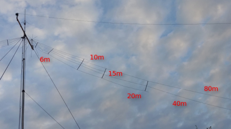 Extension to an existing fan dipole originally modeled for 40 20 and 6 meters. This modification will add 80 15 and 10 meter bands.
 -
 Optimizing a G5RV or ZS6BKW multiband wire antenna for HF operation often involves addressing common SWR issues and understanding feedline characteristics. This resource chronicles the construction and performance evaluation of a G5RV, initially built for 80m, 40m, 15m, and 10m bands, by a newly licensed Foundation operator. The author details the selection of materials, including 3.5 mm stainless steel wire for the doublet arms and enameled copper wire for the open-wire feeder, and the initial decision to omit a balun based on common online information. The narrative highlights the initial disappointing performance, characterized by high receive noise and poor signal reports on 80 meters, despite the transceiver's internal ATU achieving a 1:1 match. This led to experimentation with a coax current balun and further research into G5RV myths, such as SWR claims and the necessity of a balun. The author then describes modifying the antenna to the ZS6BKW configuration, which involves specific changes to the doublet and feedline lengths, and integrating a 1:1 current balun wound on a ferrite toroid. The modifications resulted in improved reception and transmit performance across the bands.
 -
 The Cushcraft X7 Tribander assembly and installation manual (P/N 951470, 12/97) provides comprehensive instructions for constructing this 20-15-10 meter seven-element beam antenna. It details the sequential assembly of boom sections, individual elements, and the feed system, including the _MNX7 Matching Network_. The document emphasizes critical safety precautions regarding power lines and RF exposure, alongside recommendations for proper antenna system planning and grounding. Key sections cover verification of parts, detailed boom assembly using specific aluminum tubing (e.g., BA, BB, BC, BD, BE) and brackets, and element construction with various aluminum tube sections (e.g., EA, EB, EC, ED, EE, EF) and traps like the _15 Meter Director Trap_ (TB) and _10 Meter Director Trap_ (T9). It also specifies the use of _NOALOX® conductive lubricant_ for telescoping sections and hardware to prevent galling. The manual outlines the feed system assembly, which includes feed-straps (FL1, FL2, FL3), tuning-tube insulators, and the matching network. It also mentions the optional X740 40-meter add-on kit, which requires a separate coax feed. Detailed diagrams and parts lists with metric equivalents facilitate accurate construction and ensure the antenna performs as specified.
 -
 The ZS6BKW multiband antenna, an optimized variant of the classic G5RV, features a 102-foot (31.1 m) horizontal span and a 39.1-foot ladder line matching section. This design, derived by G0GSF (formerly ZS6BKW) in the early 1980s using computer programs and _Smith charts_, aims for improved SWR across multiple HF bands compared to its predecessor. Construction details specify Wireman 554 ladder line and #14 AWG THHN copper wire for the radiators, with precise instructions for determining the velocity factor (VF) of the ladder line using an antenna analyzer or dip meter, ensuring accurate physical length for the matching section. The radiator length is electrically 1.35 wavelengths for the 20-meter band, requiring careful trimming during tuning. Field measurements with an _AIM-4170C_ analyzer by KI4PMI and NC4FB demonstrated good SWR curves and bandwidth on 6, 10, 12, 17, 20, and 40 meters. The antenna was deemed unusable on 15 and 30 meters due to very high SWR, but an LDG AT-100PRO autotuner successfully brought 6 and 80 meters into tune. Contacts were made on 80, 40, 20, and 17 meters, including a **17-meter** contact to Spain. EZNEC models for 80-6 meters are provided, along with an AutoEZ model by AC6LA, which predicted good SWR for 80-10 meters. W5DXP's modifications for an all-band HF ZS6BKW are also referenced.
 -
 Convert a Hustler 5 band 5BTV to 17 Meters An easy add on antenna project by Larry, KK5ID
 -
 A 6 dB gain Moxon rectangle antenna, designed for the 2-meter band, offers an excellent solution for hams seeking a compact, directional antenna for **SSB** operation, particularly in restricted spaces like an attic. This design emphasizes ease of construction using readily available materials such as 4mm OD brass tubing and plywood, making it an accessible project for many radio amateurs. The antenna's inherent characteristics, including a high front-to-back ratio of 37 dB and a 50-ohm feed impedance, contribute to its effectiveness in mitigating local noise and focusing radiated power. The project leverages the free MoxGen program for precise dimension calculations based on the desired frequency and wire size, and utilizes 4nec2 for pattern analysis, confirming a 3 dB beamwidth of 80 degrees. Construction involves bending brass tubing for the driven and passive elements, mounting them on an 800 x 350 mm plywood boom, and securing them with cable clips and epoxy resin. Initial SWR measurements at 144.3 MHz showed 1.6:1, which improved to 1.3:1 at 145.3 MHz across a flat band from 144.1 MHz to 145.5 MHz after adding a **coaxial choke** to mitigate common mode current.
 -
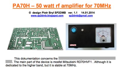 This document details the design and construction of the PA70H, a 50-watt RF amplifier for the 70MHz (4-meter) amateur radio band. Built around the Mitsubishi RD70HVF1 MOSFET transistor, the amplifier delivers 45-55W output with 3-5W input power while operating on 13.8V DC at approximately 7-8A. The PCB design incorporates multiple protection circuits including overcurrent, SWR, and temperature control. The amplifier features various control modes including GND PTT, +13.8V PTT, and RF VOX. Two versions are available: PA70HLI (requiring 100mW input with additional driver) and PA70H (for 3-5W input). The comprehensive documentation includes circuit diagrams, assembly instructions, and performance data showing successful operation from both 100mW and 3.5W input sources.
 -
 The Yaesu VX-5R, manufactured between 199x and 200x, offers a transmit frequency range covering 50-52 MHz, 144-146 MHz, and 430-440 MHz for European models, with US versions extending to 50-54 MHz, 144-148 MHz, and 430-450 MHz. Its receiver boasts an impressive wideband capability from 0.5 MHz to 999 MHz, with cellular frequencies blocked in some regions. The unit provides up to 5 watts RF output on 6 meters and 2 meters, and 4.5 watts on 70 centimeters, with selectable lower power settings down to 300 mW. This handheld transceiver utilizes a double conversion superheterodyne receiver system, featuring a 47.25 MHz first IF for FM and 45.8 MHz for WFM. Key specifications include a frequency stability of ±5 ppm across a wide temperature range and a current drain of 25-150 mA on receive. The VX-5R supports 220 regular memory channels with alpha tags, 3 home channels, and 10 NOAA weather channels, all stored in non-volatile EEPROM. Additional features include CTCSS/PL and DCS with tone search, ARS, ARTS, an internal voltmeter, and a Spectra-Scope. The device operates on a 7.2 VDC battery pack or 10-16 VDC external power, weighing 255 grams with dimensions of 58x88x27 mm. The VX-5R was also available as the metallic silver VX-5RS.
 -
 This article compares two commercial vertical antennas for the 4-meter amateur radio band: the Watson WVB-70 half-wave and the Sirio CX4-71. The Watson measures 2.03m in length, costs around £40, and exhibited adequate performance but required additional waterproofing after rain affected its VSWR readings. The longer Sirio CX4-71 (3.02m) performed noticeably better, delivering signals approximately 2 S-points stronger than the Watson. The Sirio demonstrated high build quality, a stable 1.2-1.4:1 VSWR, and weather resilience, though minor VSWR fluctuations were observed during rain and frost. Both antennas are half-wave designs requiring no ground plane radials.
 -
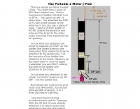 This is a simple portable 2-meter J-Pole antenna. You start with a piece of 450-Ohm Ladder Line
 -
 The ZS6BKW multi-band antenna, an optimized variant of the classic G5RV, is presented with detailed construction and tuning instructions. This resource outlines the antenna's design principles, which were developed by _Brian Austin (G0GSF)_ using computer programs and Smith charts to achieve optimal dimensions. It provides specific guidance on calculating and adjusting the lengths of the radiators (L1) and the matching ladder line (L2), emphasizing the critical role of velocity factor (VF) in achieving resonance. The article includes a step-by-step procedure for empirically determining the VF of ladder line using an antenna analyzer, ensuring accurate physical lengths for the matching section. It details the tuning process for the radiators, offering practical tips for incremental adjustments to achieve the best SWR curve. The resource presents SWR measurement results obtained with an _AIM-4170C_ analyzer across multiple bands, alongside predicted SWR graphs from an AutoEZ model. It confirms successful contacts on 80, 40, 20, and 17 meters, including a **17-meter DX contact** to Italy. EZNEC and AutoEZ models for the ZS6BKW antenna, covering 80 through 6 meters, are provided for download, allowing further analysis and customization. The document specifies component details, such as the use of Wireman 554 ladder line and #14 AWG THHN copper wire, and discusses the antenna's performance characteristics, noting high SWR on 15 and 30 meters but successful tuning on 6 and 80 meters with an external tuner.
 -
 The performance of a small magnetic loop can be improved constructing it larger, thicker or both. The antenna is covering from 12 Megahertz to 32 megahertz and adding a 156 Pico farads ceramic capacitor it resonates on the 40 meters band. by PY1AHD
 -
 Demonstrates various practical amateur radio projects and technical discussions through video episodes. One episode details cutting and retuning a _1/4 wave shorted stub_ from 101.7 MHz to 107.5 MHz to safeguard a transmitter's driver stage, alongside insights into advanced _160-meter antenna systems_ like eight-circle arrays and beverage antennas. Another segment covers upgrading firmware on an _ATS-20+_ receiver using AverDudes for improved display and functionality, and a detailed guide on using D-Star DR mode on an _ICOM ID-52A_ for international repeater programming. Additional content includes a deep dive into _OpenHamClock_ as a potential replacement for the HamClock project, updates on _Raspberry Pi 5_ running Trixie OS, and a review of the Choyong LC90 Internet radio with AI integration. The series also features "Ham College" episodes, which meticulously prepare viewers for the Technician Exam by covering topics such as antenna and transmission line measurements, SWR interpretation, and the functions of basic electronic components like rectifiers, relays, and transistors. Practical advice on coaxial cable characteristics, dummy loads, and proper soldering techniques is also provided.
 -
 The article details a specific method for performing maintenance on a crank-up tower, focusing on cable and rotator replacement without a full power pulldown. It outlines the necessary equipment, including a 2-section extension ladder with a horn attachment and a two-piece, 6-foot steel pipe, specifying a 1 1/4-inch diameter. The procedure involves lowering tower sections onto the internal pipe to slacken cables, allowing for their removal and replacement, and also describes how to replace the rotator while the tower remains upright. Key steps involve using the pipe to support tower sections, enabling access to the cables and bearings. The author, N5AR, emphasizes safety by instructing the reader to remain on the ladder at all times, rather than climbing the tower itself. The process is presented as manageable for a single operator, with the author having successfully completed the task on a _UST TX472_ tower. Specific tools mentioned include Allen wrenches and end wrenches for cable ends and bearing bolts. The method provides a practical approach for tower upkeep, minimizing the complexity often associated with such tasks and allowing for maintenance of components like cable pulleys and their bearings.
 -
 Hi-Z Antennas offers specialized high-impedance receiving systems, primarily focusing on phased vertical arrays for HF reception. Their product line includes preamplifiers designed for shortened vertical antennas, featuring optimized 15dB gain and array-matched characteristics. These components are engineered to enhance weak signal reception and improve signal-to-noise ratio across the HF spectrum. The company provides controllers for managing multiple vertical elements in a phased array configuration, enabling directional reception patterns. These systems are particularly effective for mitigating local noise and interference, a common challenge in urban and suburban operating environments. Specific offerings include solutions for 160-meter and 80-meter bands, addressing the unique requirements of low-band DXing. Technical details often reference components like the 2N3866 transistor in preamp designs and discuss concepts such as out-of-band attenuation. The focus remains on optimizing receiving antenna performance through impedance matching and active amplification, rather than transmit capabilities.
 -
 Constructing a mobile HF antenna presents unique challenges, particularly when aiming for multiband operation and robust mechanical stability. This project details N1GY's adaptation of the KM4IE $20 antenna and the _Texas Bugcatcher_ design, focusing on practical build considerations and on-the-road performance. The author shares insights from winding coils on 2-inch PVC forms and integrating a salvaged fiberglass core from an old Hamstick-style antenna to enhance structural integrity, preventing potential failures from stress on PVC joints. N1GY's build includes a custom matching coil and a commercially sourced MFJ loading coil, carefully integrated into the design. The article provides specific tap settings for bands from 75 meters to 15 meters, achieving SWRs as low as **1.2:1** on 40 meters and **1.6:1** on 75 meters. Mechanical testing involved driving at speeds up to 70 MPH on Interstate routes, confirming the antenna's durability and the effectiveness of its PVC brace system. Further modifications address real-world usability, such as simplifying antenna removal for car washes. The ground strap was updated with a Power Pole connector, and the brace attachment to the luggage rack was converted to wing nuts, reducing removal time from 30 minutes to approximately _five minutes_. This iterative design process highlights practical solutions for mobile HF operation.
 -
 The **KC0KJF** personal amateur radio page provides a collection of resources for fellow hams, particularly those interested in operations within southwest Missouri. It offers detailed listings for **Missouri repeaters** on both 2 meters and 70 centimeters, serving as a practical reference for local VHF/UHF communication. The site also includes information about the operator's station setup and antenna projects, such as a dipole and a bazooka antenna, which can offer insights into basic antenna construction and deployment. Beyond local repeater data, the page features links to the FCC Part 97 rules, essential for understanding amateur radio regulations. The operator, licensed as a Technician Class since April 16, 2001, shares his journey from Citizen's Band Radio to amateur radio, driven by a lifelong fascination with shortwave listening. This narrative provides context for the resource's focus on practical operating information and foundational regulatory knowledge. Additional content covers specific equipment like the 2-meter/70-centimeter Arrow Antenna, useful for hams considering portable or fixed station VHF/UHF setups.
 -
 The NB6Zep Antenna, an electrically shortened 80-meter end-fed wire, addresses space constraints for low-band operation by integrating two loading coils into a 37-foot wire. This design, modeled with _EZNEC_, explores configurations like the quarter-wave sloper and inverted-L, with the latter providing a more vertical radiation pattern and practical backyard deployment. The resource details specific coil construction, recommending 21 uH coils made from _BW coil stock #3026_ or similar, and outlines wire segment lengths for optimal tuning. Performance analysis indicates a radiating efficiency of approximately 27% with good ground conductivity, resulting in a signal typically 3-4 dB down compared to a full-size quarter-wave vertical. The antenna exhibits a narrow bandwidth, around 50 kHz, due to its high Q, necessitating a tuner for broader band operation. Feedpoint impedance is low, with ground resistance playing a critical role in achieving a usable SWR. The article emphasizes the importance of an effective ground rod at the feedpoint for proper operation and tuning, suggesting an antenna analyzer for precise adjustments. It confirms the antenna's suitability for DX, citing successful contacts from Oregon to the East Coast and Hawaii on a 160-meter variant, making it a viable option for urban operators seeking low-angle radiation on 80 meters.
 -
 Demonstrates a range of specialized radio frequency equipment and consulting services for amateur and professional applications. The offerings include _Vector-Finder_ direction finding antennas, various test equipment such as _gate dip meters_ and RF sniffers, and communications receiving adjuncts. Additionally, the company produces satellite antennas for weather satellite reception, voice amplification devices like the _Flex-Mike_, and custom prototype circuit boards. The company's product line addresses needs for precise RF measurement, signal detection, and specialized antenna systems, particularly for direction finding and satellite communications. Their historical association with National Radio (HRO) suggests a legacy in radio technology. The site also highlights a subsidiary, Sierra Mountain Products, which offers outdoor recreational gear, indicating a diversification beyond core RF manufacturing.
 -
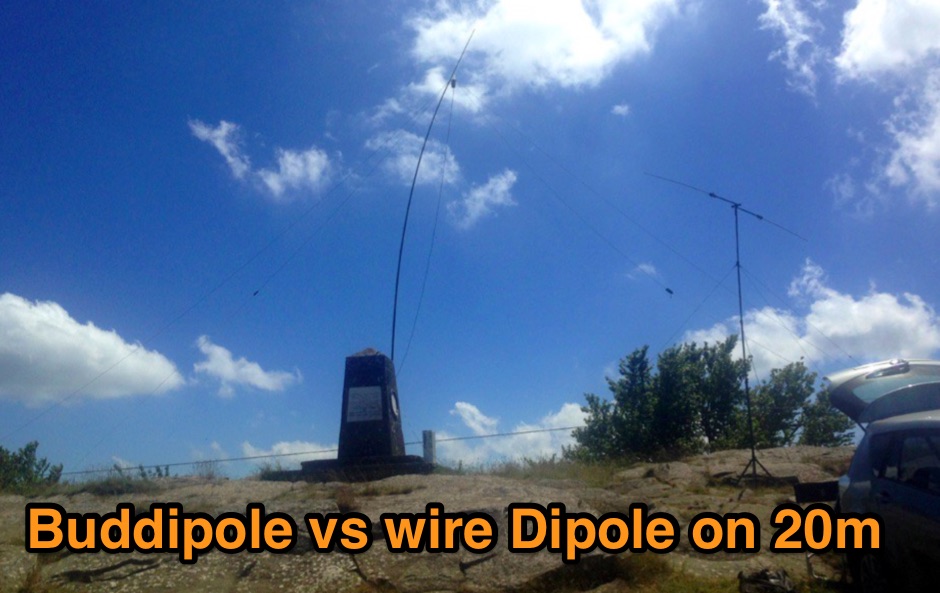 During a club's "Filetto Day" event, a comparative field test was conducted between a **Buddipole** antenna and a homemade 20/40-meter wire dipole. The author, IW5EDI, performed this personal evaluation from a mountain top at 1500 meters above sea level, utilizing a Yaesu FT-857D transceiver to switch between antennas. The observations on the 20-meter band indicated that the wire dipole consistently delivered significantly stronger signals compared to the Buddipole. Additionally, the Buddipole exhibited higher levels of **QRM** during the listening tests. The commercial Buddipole, known for its multiband capability and compact size with a self-supporting tripod, was contrasted with the simpler, larger wire dipole, which required a fiberglass fish pole for support. This direct comparison highlights practical differences in performance and deployment between a popular portable commercial antenna and a basic wire antenna in a real-world operating environment.
 -
 Cushcraft A3S performances with the A743 kit to add 30 and 40 meters
 -
 An amplifier made using an old HT-41 Hallicrafters Amplifier and adding the 160 meters band By W4NFR
 -
 Operating the _Icom IC-746_ HF/VHF transceiver often presents specific technical questions, and this resource compiles a comprehensive Frequently Asked Questions (FAQ) document in an ASCII text format. It details common inquiries and solutions related to the rig's functionality, accessories, and potential modifications. The content is structured into distinct sections addressing general information, power supplies, antennas, microphones, keyers, amplifiers, TNC integration, and optional IF filters. The FAQ provides practical guidance on topics such as configuring the internal automatic antenna tuning unit (ATU), selecting appropriate power supplies, and understanding microphone pin-outs. It also delves into advanced subjects like computer control via CI-V, wiring for PSK31 operation, and troubleshooting common issues like low S-meter readings on 2m FM or loose tuning shafts. Specific questions cover the installation of optional IF filters, comparing Inrad versus Icom filters, and optimizing filter combinations for various modes. Furthermore, the document outlines various hardware and firmware modifications, including those for increasing monitor volume, replacing LCD driver transistors, and implementing a "poor man's TCXO." It even touches upon untested modifications, such as replacing PIN diodes in the demodulator. The FAQ also lists manual errata and discrepancies, offering a robust knowledge base for IC-746 owners seeking to optimize their station or resolve operational challenges.
 -
 The W6NL Moxon Yagi is a high-efficiency two-element 40m Yagi that uses cross elements to provide both loading and Moxon coupling, addressing the challenge of deploying a directional antenna on the 40-meter band. This resource details the transformation of a _Cushcraft XM240_ Yagi into this Moxon configuration, replacing the original loading coil LCA sections with four new assemblies. The guide provides comprehensive instructions for building the boom and elements, including specific dimensions for new sections and tee loading elements, along with detailed drawings and a full parts list for the conversion. Performance data indicates the converted antenna achieves **10.73 dBi** gain at 7.050 MHz with 99.5% efficiency and a high front-to-back ratio. The VSWR bandwidth is over **300 kHz**, ensuring good performance across a significant portion of the 40m band. Construction involves reinforcing element sections, attaching tee loading elements with U-bolts, and implementing element guying using materials like _Phillystran_ to manage sag and maintain structural integrity.
 -
 About the Cushcraft A3S with A743 add-on for 30 an 40 meters
 -
 Accessing this interface provides entry to one of the largest databases for amateur radio voice repeaters, encompassing over 8000 entries from more than 60 countries. The resource supports both desktop and mobile access, with a default display based on browser type, or forced via a "force" parameter (e.g., relais.dl3el.de?force=mobile). Users input a QTH-locator to find local repeater information. The database integrates FM-Funknetz servers and hotspots, potentially creating duplicate entries but ensuring new FM-Funknetz repeaters are immediately displayed. DMR repeater information, including status and talkgroup configurations, is sourced directly from DMR+ / ircDDB and Brandmeister systems, with real-time updates for active and default talkgroups. C4FM/Wires-X installations, particularly MMDVM-based gateways not listed in Yaesu's database, are identified through Brandmeister dashboard descriptions, marked with "W-x" or "W-x#MMDVM" for manual entries. D-Star repeater data from ircddb or QuadNet2 is also incorporated, with entries marked (i), (o), or (d) for manual additions. An APRS interface allows searching by callsign, using Sassan, DL3NCK's database, and offers a mobile-friendly, auto-refreshing display that follows an APRS station. Output data can be generated in GPX format for offline smartphone maps or CSV for spreadsheet applications. The database also attempts to determine valid repeater offsets based on IARU region and frequency, indicated by a "." after the frequency.
 -
-
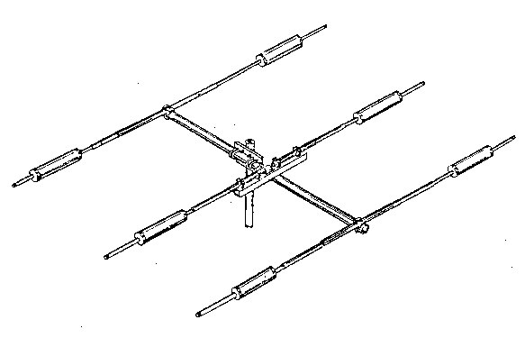
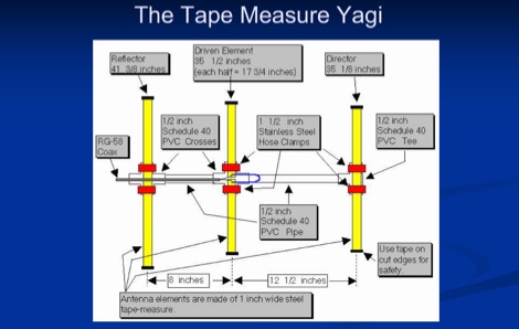 A presentation of the Yagi Antennas, and other interesting tid-bits by Brian Mileshosky. The document provides an in-depth exploration of the Yagi-Uda antenna, detailing its historical development, design principles, and performance characteristics. Originally described in the 1920s, the Yagi antenna features a driven element and parasitic elements, including reflectors and directors, which collectively determine its behavior. The document highlights how element lengths, diameters, and spacing influence gain, impedance, and directivity. It also discusses the antenna's reciprocal nature and presents data on typical gain values for various element configurations. Additionally, the text covers practical considerations, such as the construction of a "Tape Measure Yagi" for amateur use, and touches on related antenna types like dipoles and their application in Near Vertical Incident Skywave (NVIS) communication.
 -
 Constructing a compact directional antenna for the 17-meter band, this resource details the build process for a Moxon rectangle, a two-element Yagi variant with folded-back elements. It covers the antenna's evolution from the _VK2ABQ beam_ and provides specific dimensions for a version built using fishing pole whips. The content includes a discussion of the antenna's radiation pattern, feedpoint impedance, and its inherent front-to-back ratio, which is often superior to a standard two-element Yagi. Practical considerations for element spacing and material choices are also addressed, alongside a visual representation of the antenna's physical layout. Performance data presented includes a comparison showing the Moxon rectangle's **2.5 dB gain** over a half-wave dipole and a front-to-back ratio of **20 dB**. The resource also touches upon the antenna's relatively wide bandwidth for a two-element beam and its suitability for portable operations due to its compact footprint. It offers insights into optimizing the design for specific operating conditions and discusses the advantages of its lower take-off angle compared to omnidirectional wire antennas, making it effective for DX contacts on the 17-meter band.
 -
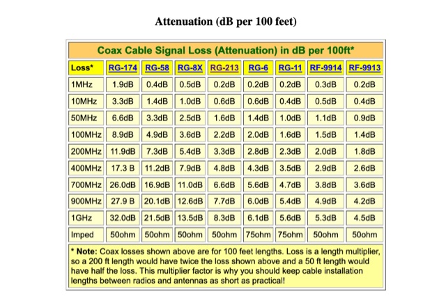 The resource provides coaxial cable attenuation data, listing signal loss in dB per 100 feet for various cable types across a frequency range from 1 MHz to 5.8 GHz. The initial table details attenuation for cables such as _RG-58_, _RG-8X_, and RG-213, with impedance values of 50 ohm or 75 ohm, at frequencies up to 1 GHz. For example, _RG-58_ exhibits **0.4 dB** loss at 1 MHz and **21.5 dB** loss at 1 GHz per 100 feet. A subsequent table expands on this data, including LMR series cables like _LMR-400_ and LMR-600, along with other types such as 9913F7 and RG214. This section covers frequencies from 30 MHz to 1,500 MHz, also noting the outer diameter of each cable. For instance, _LMR-400_ (0.405" diameter) shows **0.7 dB** loss at 30 MHz and 5.1 dB loss at 1,500 MHz per 100 feet. The final section focuses on VHF/UHF/Microwave amateur and ISM bands, presenting attenuation in dB per 100 feet (and meters) for frequencies including 144 MHz, 450 MHz, and 2.4 GHz. This table includes larger diameter hardline options like 1/2" LDF and 7/8" LDF, in addition to flexible coaxial cables. For example, 1/2" LDF cable demonstrates **0.85 dB** loss at 144 MHz and 6.6 dB loss at 2.4 GHz per 100 feet. DXZone Focus: Coaxial cable attenuation | LMR-400 | RG-58 | 5.8 GHz
 -
 Presents a concise guide for Amateur Radio operators participating in Jamboree-on-the-Air (JOTA), an annual event connecting approximately 500,000 Scouts and Guides worldwide via ham radio. The resource details how to initiate a voice contact, including the use of "CQ Jamboree JOTA" and proper signal reporting with the RST system. It also outlines the typical exchange information, such as name, QTH, Scout rank, and age, encouraging participants to practice their responses. Authored by Bill Wetherill, N2WG, the brochure provides a practical phonetics chart and a comprehensive Morse code dictionary, including punctuation and prosigns like AR and SK. It clarifies rules for third-party operation under the direct supervision of a licensed operator, noting restrictions on international contacts without specific government agreements. Additionally, the guide lists recommended World Scout Frequencies for SSB and CW across 80, 40, 20, 17, 15, 12, and 10 meters, emphasizing courteous operating procedures. It includes a section on common Q-signals like QRM, QRN, and QSL, alongside the Amateur's Code, which stresses considerate, loyal, progressive, friendly, balanced, and patriotic conduct.
 -
 The article, "Using 75 Ohm CATV Coaxial Cable," details methods for employing readily available 75-ohm CATV hardline in standard 50-ohm amateur radio setups. It addresses the inherent impedance mismatch and practical considerations, such as connector compatibility, for hams seeking cost-effective, low-loss feedline solutions. The resource specifically contrasts common 50-ohm cables like RG-8, RG213, and _LMR-400_ with 75-ohm hardline, highlighting the latter's lower loss characteristics, particularly at VHF and UHF frequencies. It explores two primary approaches to manage the impedance difference: direct connection with an acceptable SWR compromise and precise impedance transformation. The direct connection method acknowledges that a perfect 1:1 SWR is not always critical, especially when using low-loss coax. For impedance transformation, the article explains the use of half-wavelength sections of coax to reflect the antenna's 50-ohm impedance back to the transmitter, noting its single-frequency effectiveness. It also briefly mentions transformer designs using toroid cores and a technique involving two 1/12 wavelength sections of feedline for broader bandwidth. The content further clarifies the concept of _velocity factor_ for calculating electrical versus physical cable lengths, providing a generic formula for precise length determination. It notes that while half-wave matching is practical for 10 meters and above, it can result in excessively long runs for lower bands like 160 meters, potentially adding **250 feet** of cable. The article also mentions achieving a usable bandwidth of 28.000 MHz up to at least **28.8 MHz** on 10 meters with specific transformation techniques.
 -
 Gold Line, a manufacturer, provides a range of professional audio test and analysis equipment, including specific products like the **ZM1 Impedance Meter**, which is relevant for amateur radio operators needing to characterize antenna systems. The site also lists various noise sources and microphones, such as the TEF04 Mic, indicating a focus on audio signal integrity and measurement. The resource details contact information for repairs, calibration, quotations for specific products like the ZM1 and ZM1P, and technical support, with distinct email addresses and phone numbers provided for each function. This structured contact approach facilitates direct engagement with the appropriate department for specific inquiries. Operational changes effective March 1, 2019, are noted, directing users to VLDESIGN for repair and calibration, and to Partha Chen for ZM1/ZM1P quotations. Louis Pittsley is designated for technical support, with a general inquiry phone number also available, outlining the company's support infrastructure.