Search results
Query: end feed
Links: 94 | Categories: 0
-
 Presents the construction of a 2-meter **Skeleton Slot Yagi** stack, detailing the design process and practical considerations for VHF operation. The author shares insights from building and testing this antenna, emphasizing its performance characteristics for local and extended range contacts. The project outlines the specific dimensions and materials used, providing a clear path for other radio amateurs to replicate or adapt the design for their own stations. The resource covers the unique aspects of the Skeleton Slot radiator, explaining how its geometry contributes to gain and pattern control. It includes discussions on impedance matching and feedline considerations crucial for optimizing power transfer and minimizing SWR. The article draws on real-world testing, offering practical results that validate the theoretical design. This project serves as a valuable reference for those interested in custom VHF antenna solutions.
 -
 A wire antenna feeded with an unsymmetrical feed and a 1:4 balun can be tuned from 6 to 80 meters band but can be noisier than a dipole and cause RF in the shack
 -
 The NB6Zep Antenna, an electrically shortened 80-meter end-fed wire, addresses space constraints for low-band operation by integrating two loading coils into a 37-foot wire. This design, modeled with _EZNEC_, explores configurations like the quarter-wave sloper and inverted-L, with the latter providing a more vertical radiation pattern and practical backyard deployment. The resource details specific coil construction, recommending 21 uH coils made from _BW coil stock #3026_ or similar, and outlines wire segment lengths for optimal tuning. Performance analysis indicates a radiating efficiency of approximately 27% with good ground conductivity, resulting in a signal typically 3-4 dB down compared to a full-size quarter-wave vertical. The antenna exhibits a narrow bandwidth, around 50 kHz, due to its high Q, necessitating a tuner for broader band operation. Feedpoint impedance is low, with ground resistance playing a critical role in achieving a usable SWR. The article emphasizes the importance of an effective ground rod at the feedpoint for proper operation and tuning, suggesting an antenna analyzer for precise adjustments. It confirms the antenna's suitability for DX, citing successful contacts from Oregon to the East Coast and Hawaii on a 160-meter variant, making it a viable option for urban operators seeking low-angle radiation on 80 meters.
 -
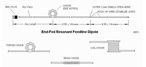 Experiences with the end-fed dipole based on the concepts presented by J. Taylor in an article titled RFD-1 and RFD-2: Resonant Feed-Line Dipoles in QST. August 1991.
 -
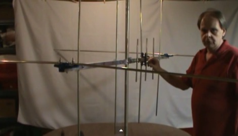 6m/2m/70cm Yagi Antenna Built from Old TV Antenna This turned out to be a great little antenna. It works the 6 meter, 2 meter and 70 centimeter bands. You can use one common feedpoint or two seperate feedpoints depending on how you would like to connect this antenna to your transceiver.
 -
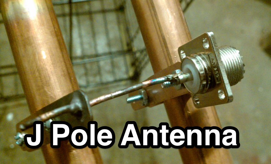 The copper J-Pole antenna soldered in a couple of hours with an interesting method to setup the feeding point
 -
 Wondering whether to spend a fine day with the YL or with the antenna? This article may help you decide by W1GV
 -
 The _Sci.Electronics FAQ: Repair: RFI/EMI Info_ document, authored by Daniel 9V1ZV, provides a detailed analysis of computer-generated RFI/EMI, focusing on its impact on radio reception. It identifies common RFI sources such as CPU clock rates (e.g., 4.77 MHz to 80 MHz), video card oscillators (e.g., 14.316 MHz), and even keyboard microprocessors, all of which generate square-wave harmonics across HF and L-VHF regions. The resource outlines a systematic procedure for pinpointing RFI origins, including disconnecting peripherals and using a portable AM/SW receiver with a ferrite rod antenna to localize strong interference sources. The document categorizes RFI mitigation into shielding, filtering, and design problems, offering practical solutions for each. It recommends applying conductive sprays like _EMI-LAC_ or _EMV-LACK_ to plastic casings of radios, monitors, and CPUs to create effective Faraday cages, emphasizing proper grounding and avoiding short circuits. For filtering, the guide suggests using line filters, ferrite beads, and toroids on power and data lines, and small value capacitors (e.g., 0.01 uF for serial/parallel, 100 pF for video) to shunt RFI to ground. It also discusses the use of bandpass, high-pass, low-pass, and notch filters on the receiver front-end or antenna feed to combat specific in-band noise.
 -
 Operating a ham station often involves encountering radio frequency interference (RFI), RF feedback, or RF burns, which are frequently misattributed to poor equipment grounding. This resource meticulously dissects these assumptions, asserting that RF grounds on the operating desk often merely mask more significant system flaws. It identifies five primary causes for RF problems, including antenna system design flaws, proximity of the antenna to the operating position, DC power supply ground loops, equipment design defects, and poorly installed connectors or defective cables. The content emphasizes that issues like "hot cabinets" or changes in SWR when connecting a ground indicate substantial RF flowing over wiring or cabinets, a phenomenon known as common-mode current. The article provides detailed explanations of common-mode current generation, particularly from single-wire fed antennas like longwires, random wires, and OCF dipoles, which inherently present high levels of RF in the shack. It also illustrates how vertical antennas, lacking a perfect ground system, can excite feed lines with significant common-mode current. Through simulations, the author demonstrates how a dipole without a proper _balun_ can cause RF problems at the operating desk, showing current patterns and voltage distributions on feed line shields. The discussion extends to the proper application of _RF isolators_ and _ferrite beads_, clarifying their role in modifying common-mode impedance on cable shields and cautioning against their use as a band-aid for fundamental system defects. The resource advocates for correcting the actual source of RF problems, such as antenna system issues or poor connector mounting, rather than relying on internal shack grounding or isolators. It highlights that properly functioning two-conductor feed lines, like coaxial or open-wire lines, should result in minimal RF levels at the operating position, even without a desk RF ground. The author shares personal experience, noting that his stations since the late 1970s have operated without RF grounds at the desks, relying instead on proper antenna system design and feed line integrity.
 -
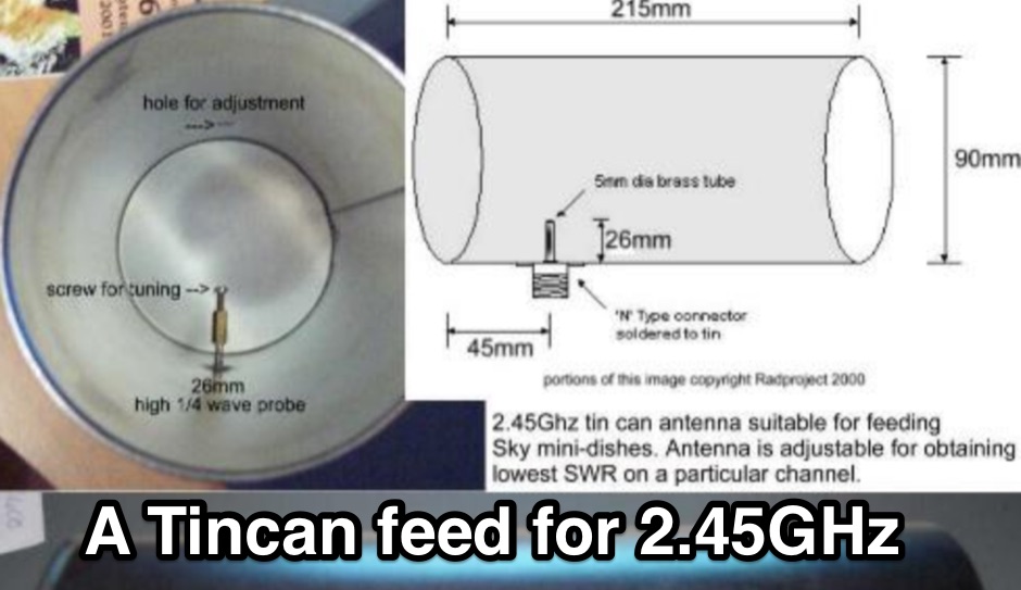 Construction details for a simple but effective antenna for 2.45Ghz wireless lan use.
 -
 1:49 UNUN using two stacked FT240-43 cores for end fed halfwave antenna. To match the end fed half wave antenna to the coaxial feeder, it is necessary to have a matching network or transmission line transformer.
 -
 1.5 dB of matched line loss can be calculated for a given transmission line using this online tool, which employs a model calibrated from empirical data. The calculator allows radio amateurs to input specific transmission line types, such as _RG-8_ or _RG-58_, and then determine the expected signal attenuation. This is crucial for optimizing antenna system efficiency and understanding power delivery to the radiating element, especially for HF and VHF operations where feedline losses can significantly impact performance. Beyond matched loss, the calculator also provides an estimate for mismatched loss if the Standing Wave Ratio (SWR) is specified. This feature helps operators quantify the additional power loss due to impedance discontinuities between the transceiver, feedline, and antenna, which is a common concern in amateur radio installations. Accurate loss calculations are vital for effective station design and for predicting actual radiated power. The tool's utility extends to various operating scenarios, from fixed station setups to portable deployments, aiding in the selection of appropriate feedline lengths and types to minimize signal degradation. Understanding these losses is a fundamental aspect of maximizing the effectiveness of any amateur radio antenna system.
 -
 This 6 meter 2 element yagi antenna is simple, compact and effective antenna for 50 Mhz. The design antenna was optimized with AO for best match to 50 ohms, no matching network. A choke balun is recommended to decouple feedline currents.
 -
 This web article details the construction of a 4-meter band coaxial dipole antenna, designed for operation between **70.000 MHz and 70.500 MHz**. The resource provides a bill of materials and step-by-step assembly instructions for a half-wave dipole constructed from _RG-58_ coaxial cable. The design specifies a direct 50 ohm feedpoint impedance, eliminating the need for an external matching network. Construction photographs illustrate the stripping and soldering processes for the coaxial cable elements, ensuring proper electrical connection and physical integrity. The article includes specific dimensions for the radiating elements, derived from calculations for the 70 MHz band. The project outlines the physical dimensions required for resonance at 70 MHz, with the outer braid forming one half and the inner conductor forming the other. The feedline connection is directly to the coaxial dipole's center, maintaining a 50 ohm characteristic impedance. While the article does not present SWR plots or VNA sweeps, it focuses on the mechanical construction and dimensional accuracy for achieving a functional 4-meter dipole. The design is intended for fixed station use, with no specific mention of polarization or height above ground, but implies a standard horizontal orientation for dipole operation. DXZone Focus: Web Article | 4m Coaxial Dipole | Construction Guide | 50 ohm Feed
 -
 A multi band antenna for HF band capable to operate from 10 to 80 meters band depending on wire lenght loaded with a small inductance neat the feed end.
 -
 Constructing an End-Fed Half-Wave (EFHW) antenna offers a practical solution for HF operators seeking a multiband wire antenna without the need for extensive radial systems. This design typically employs a high-impedance transformer at the feed point, matching the antenna's inherent high impedance to a 50-ohm coaxial feedline. The article specifically details a 2012 approach, focusing on a transformer with a 49:1 turns ratio, which is a common configuration for EFHW antennas. The resource outlines the construction of a wire element cut for a half-wavelength on the lowest desired band, with specific coil arrangements enabling operation on harmonically related bands such as 40m, 20m, and 10m. It discusses the physical dimensions and winding details for the matching transformer, often utilizing a ferrite toroid core to achieve the necessary impedance transformation. The content provides insights into the operational principles and practical considerations for deploying such an antenna, including methods for tuning and optimizing performance across multiple amateur radio bands. While acknowledging that the presented information from 2012 may be superseded by newer insights, it serves as a foundational reference for understanding EFHW antenna theory and construction.
 -
 A 20-meter window frame stealth antenna, based on a design by _PD7MAA_, utilizes a single 620cm wire loop for discreet installation. The feeding mechanism employs a _4C65_ toroidal core, where the antenna loop functions as a single-turn secondary, and the feedline wraps twice. Tuning is achieved via a 30cm twisted wire stub, allowing for SWR adjustment within the 20m band. This design is specified for QRP operation, with a maximum power limit of **25 Watts** to prevent core saturation or arcing. Wire selection recommendations include thin, insulated copper wire (0.75mm to 1mm) for blending with architectural elements. The guide focuses on practical construction steps for a low-profile 14MHz antenna.
 -
 The Tri-pole antenna, a clever modification of a standard dipole, allows for dual-band operation by integrating a third element. This design effectively shortens the overall dipole length by 10 to 20 percent, simplifying antenna rotation and offering a compact footprint. KK4OBI's article delves into the operational principles, using a 6 and 10-meter Tri-pole as a primary example, and provides comprehensive instructions for constructing any Tri-pole antenna within the 6 to 15-meter range. Key to the Tri-pole's performance is its off-center feed, necessitating a common mode choke at the feed point for optimal tuning and reduced noise. The author outlines a methodical approach to determining element dimensions, starting with a vertical element frequency calculated as 0.47 times the sum of the desired upper and lower band frequencies. This calculation, along with K-values derived from trend lines, guides the initial lengths for the horizontal arms, demonstrating how a 10m-6m Tri-pole can achieve a total horizontal length 78% shorter than a conventional 10-meter dipole. Tuning and balancing are critical, with the article detailing adjustments to arm lengths and the vertical element to achieve balanced SWR values, as validated through 4NEC2 simulations. Radiation patterns are analyzed at various elevations, showing gains around 5.7 dBi and favorable take-off angles for DX contacts. Construction details specify aluminum tubing dimensions, U-bolts, and an SO-239 connector, emphasizing the importance of a ferrite-based choke for wideband operation.
 -
 This type of antenna is a popular antenna design as the performance is very good across the HF bands and requires little or no tuning. It’s a dipole fed off center with a 4:1 balun at the offset feed point. The antenna shown covers 80, 40, 20 and 10 meters. The formula can also be used to adjust the overall length to cover more or fewer bands and the resulting overall length. 160-10m, 80-10m or 40-10 meters depending on your available space. Other bands will require a tuner.
 -
 Constructing a dual-band antenna for 40 and 20 meters often involves compromises in size or complexity. This resource presents a compact _open sleeve dipole_ design that addresses these challenges by using 450-ohm ladder line and folded elements to achieve a total length of approximately **17.17 meters**, significantly shorter than a full-size 40-meter dipole. The design leverages electromagnetic coupling, where a primary radiator handles the 40-meter band, and a second conductor resonates on 20 meters without direct electrical connection. This configuration eliminates the need for traditional traps, loading coils, or switching components, simplifying construction and reducing potential loss points. The antenna is fed with RG-58C/U coaxial cable, and a common-mode choke is recommended at the feed point to suppress sheath currents, ensuring a cleaner radiation pattern and minimizing RF in the shack. The design is well-suited for portable operations, field deployments, temporary installations, and restricted urban environments where space is a premium, offering solid performance on both HF bands.
 -
 A news site focused on DXing and contesting, DXNews.com provides daily updates on upcoming **DXpeditions**, contest announcements, and general **amateur radio news**. The site features a continuously updated feed of articles detailing call signs, operating dates, IOTA references, and specific contest participation plans for various DX operations. Content includes detailed reports on planned activities from rare and semi-rare DX entities, often with information on operators, bands, modes, and QSL routes. It also covers major amateur radio contests, offering insights into rules, participating stations, and results. The archive depth extends back many years, providing a comprehensive historical record of DX activity. This resource is ideal for experienced DXers and contesters seeking timely information to plan their operating schedules, track rare DX entities, and stay informed about the global DX scene. It also serves general amateur radio operators interested in following significant events and operations within the DX community.
 -
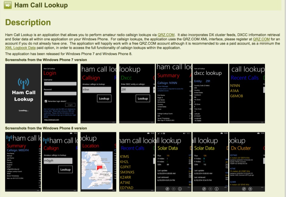 Ham Call Lookup is an windows phone app that allows you to perform amateur radio callsign lookups via QRZ.COM. It also incorporates DX cluster feeds, DXCC information retrieval and Solar data all within one application on your Windows Phone. For callsign lookups, the application uses the QRZ.COM XML interface, please register at QRZ.COM for an account if you do not already have one. The application will happily work with a free QRZ.COM account although it is recommended to use a paid account, as a minimum the XML Logbook Data paid option, in order to access the full functionality of callsign lookups within the application.
 -
 The PAC-12 Antenna, a multi-band portable vertical, is meticulously detailed in this construction article by James Bennett, _KA5DVS_. The design emphasizes ease of homebrewing using readily available components from local hardware stores, including replaceable loading coils. It outlines the preparation of the 72-inch telescoping whip (originally from Radio Shack, with an alternate source now provided by _Pacific Antenna_), the construction of the loading coils from PVC risers, and the fabrication of the aluminum rod base sections. Specific instructions cover threading aluminum rod with a _1/4-20 threading die_ and assembling the feedpoint insulator with a BNC connector, along with recommendations for radial deployment. KA5DVS, an avid traveler and QRP enthusiast, developed the PAC-12 to address the bulkiness of random wire setups and the limitations of commercial portable antennas like the Outbacker or SuperAntennas MP1. His goal was a lightweight, packable antenna that disassembles into 12-inch sections, achieving an assembled length of approximately 8 feet. The design strategically places the loading coil away from the base for improved efficiency. The PAC-12 notably placed first in efficiency compared to a quarter-wavelength wire vertical at the HFPack antenna shootout during the Pacificon conference in October 2001, demonstrating its practical performance for field operations. Appendix C showcases various _NJQRP Club_ members' PAC-12 constructions, including a 20m beam made with multiple PAC-12 elements.
 -
 HyEnd is a dutch amateur radio antenna manufacturer. Makers of the popular HyEndFeed Antennas, produce Baluns, bandpass filters and selle Line isolators, coax cables and connectors.
 -
 Extended Double Zepp measurements for all ham bands, and online calculator. The antenna is constructed much like an ordinary Dipole antenna but with 5/8 Wavelength Elements matched with an added Impedance Matching Section of balanced feed line
 -
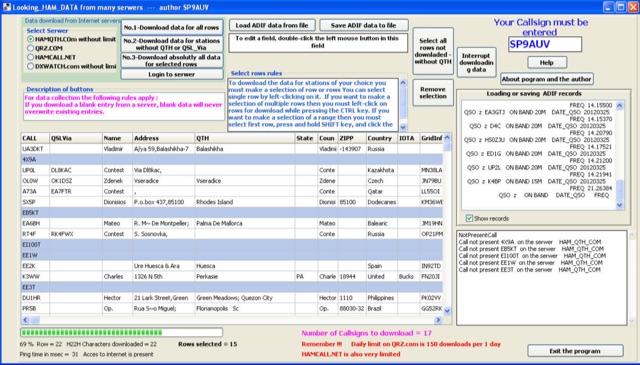 The program serves to assist in a ham-radio activities secretarial with his hobby , such as Printing QSL cards or print labels directly from the program , printing envelopes and mailing envelopes for the feedback you send direct QSL cards, download address for sending cards direct from QRZ.COM or for any station. Checking whether for the QSO and his country is present QSL bureau.
 -
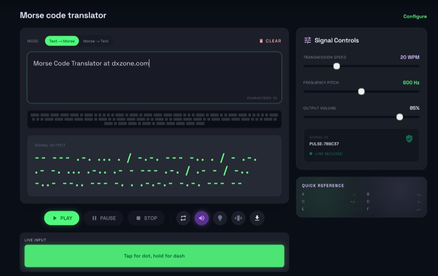 The morsecodeworld.org web application provides an online Morse code decoder and encoder, facilitating real-time conversion between text and International Morse code. It supports adjustable transmission speed (Words Per Minute), sidetone frequency pitch (Hz), and output volume, allowing users to customize their learning and practice environment. The tool includes a quick reference chart for the Morse alphabet and focuses exclusively on International Morse, aligning with contemporary amateur radio licensing and on-air practices, distinguishing it from historical American Morse code. This web-based utility enables users to type text for encoding into Morse audio or paste Morse code for decoding into plain text, offering immediate feedback on timing and character spacing. It supports both visual and auditory learning by providing adjustable parameters for speed and tone. The platform is designed for self-assessment, encouraging users to practice copying and sending, and to identify and correct common errors in character recognition and timing.
 -
 This project involves constructing a dual-band Moxon antenna, optimized for ham radio enthusiasts, with functionality on both the 10-meter and 6-meter bands. The antenna is designed to operate using a single 50-ohm feedpoint, acting as a mini-beam on 28 MHz (10 meters) and as a 2-element Yagi on 50 MHz (6 meters). Performance-wise, it offers a 4.0 dBd gain on 10 meters and 4.3 dBd on 6 meters, with impressive front-to-back ratios of 30 dB and 11 dB, respectively. Builders like Aleks (S54S) and Marcio (PY2OK) have successfully brought this design to life using the provided specifications. Aleks noted that bending the corners of the structure proved especially useful during assembly. The project comes with a detailed parts list, highlighting the use of aluminum tubes with different diameters and lengths to form essential components like the reflectors and radiators. For those looking to fine-tune the antenna, adjustments can be made by altering the length of certain parts that fit into larger tubes. The feeding system is equipped with a balun to accommodate different power levels, making the design versatile enough to handle outputs of either 300 watts or 1 kilowatt.
 -
 This article presents the C-Pole antenna project, a compact, ground-independent vertical antenna designed for amateur radio operators. It features a folded half-wave dipole configuration that eliminates the need for radials, making it suitable for various locations, especially in deed-restricted areas. The C-Pole offers efficient performance with a 2:1 SWR bandwidth of approximately 3%, and it can be easily constructed using common materials. Additionally, the article discusses practical aspects such as feed-point impedance transformation and balun design to optimize functionality and minimize losses.
 -
 The article describes the construction of a 1:49 impedance transformer designed to match the high impedance (around 2500Ω) of an end-fed half-wave (EFHW) dipole antenna to the 50Ω impedance of a typical transceiver. The EFHW is a popular portable antenna due to its simple construction, but feeding it can be challenging compared to a center-fed dipole. The transformer was built using an FT240-43 ferrite toroid core, with 2 primary and 14 secondary windings for a 1:49 impedance ratio. A capacitor was added in series with the primary winding to improve performance at higher frequencies. The author compared versions with one and two cores, and found that 100pF worked best for the single core design while 200pF was optimal for the dual core transformer.
 -
 Hamradio_copilot is an open-source tool designed for DXers and contesters who need real-time situational awareness. It is ideal for operators who want to visualize propagation trends instantly rather than scrolling through raw text streams of cluster spots. Rally acting as a copilot for your station, this tool transforms raw data into actionable intelligence. By visualizing Signal-to-Noise Ratios (SNR) across different bands, it helps operators make quick decisions on which band to prioritize or where to point their antennas, effectively showing not just who is on air, but where the propagation is currently open from your location. This is a fantastic information for avid contesters. The software aggregates data from two primary services: - Reverse Beacon Network (RBN) via Telnet. - PSK Reporter via MQTT feeds. It processes this data to generate a comprehensive HTML report featuring SNR heatmaps and statistical breakdowns by ITU Zone. Users can filter data by specific zones or country codes (ADIF), analyze historic time ranges, and optionally integrate solar weather data. The complete source code is available on GitHub, allowing for community customization. It is written in Python and uses SQLite for data management.
 -
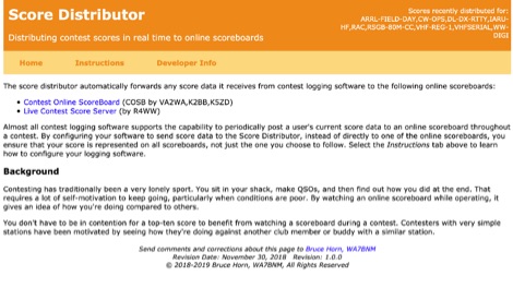 The Score Distributor facilitates real-time score forwarding for amateur radio contests, automatically transmitting data from various logging software to multiple online scoreboards. By configuring logging applications to send score data to the Distributor, operators ensure their current score is simultaneously represented on platforms like the _Contest Online ScoreBoard_ (COSB) and the Live Contest Score Server by R4WW. This system eliminates the need to choose a single scoreboard, providing broader visibility for participants. This utility enhances the competitive experience by allowing contesters to monitor their performance against other stations throughout an event. Observing real-time standings can provide significant motivation, particularly during periods of challenging propagation or when striving to maintain pace with club members or peers. The platform supports almost all major contest logging software, simplifying integration for a wide range of operators. Developed by WA7BNM, the Score Distributor was last revised on June 14, 2023. It aggregates score data, offering a unified point of submission that then disseminates the information, ensuring a **single point of entry** for broad scoreboard coverage and improving the dynamic feedback loop for participants.
 -
 Andrew Georgakopoulos, SV1DKD, modeled the End-Fed Half Wave (EFHW) antenna using MMANA-GAL software. He evaluated the EFHW-8010-2K from Myantennas.com for field operations, comparing it to random wires, OCFD, and dipole antennas. His results showed similar performance to OCFD, confirming EFHW's practical feeding advantage but with potential high-voltage risks at the feed point
 -
 The Butternut HF2V, originally a two-band vertical antenna for 80m and 40m, was enhanced by the user to include 30m and 20m bands for better digimode DX work during the solar minimum. The additions used components adapted from the HF6V and innovative methods for the 20m addition, either through a parallel vertical element or a lower-mounted independent element, minimizing band interaction. This modified four-band antenna now supports high power across popular HF bands using a single feedpoint.
 -
 This presentation on antennas is a practical guide for amateur radio operators. The key takeaway is that the best antenna for your station depends on your constraints and goals. There is no magic solution and buying a wire antenna is not recommended as it might be expensive and not as effective. The presentation covers different antenna types including dipoles, verticals, Yagis and loop antennas. Important factors to consider when choosing an antenna include SWR, feeder types, and whether you need a balun. The author emphasizes that ATUs don’t improve a poor antenna and advises against obsessing over SWR readings.
 -
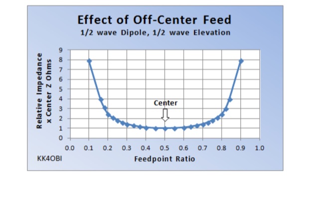 The behavior of a straight dipole and its L-form is examined in terms of impedance and SWR. By adjusting the feed point or bending angle, impedance variation is observed. Impedance shifts symmetrically as the feed point deviates, leading to recommendations for optimal ratios. Model simulations aid in understanding and fine-tuning, crucial for achieving a 50 Ohm match. Practical tuning guidelines ensure efficient antenna performance.
 -
 Twigger is a very lightweight, free ham radio logger designed for Windows, offering seamless integration with transceivers via _TCI_ or OmniRig. This software stores all logged contacts in a SQLite database, with the flexibility to export daily ADIF files for import into a main logger or to send real-time QSO data via UDP in N1MM XML format. It also supports direct, real-time uploads to popular online logbooks like Clublog and QRZ.com, streamlining the logging process for active operators. The application has seen continuous development, with version 1.1.34 fixing an ADIF log importer bug and earlier versions adding crucial features like WSJT-X/JTDX UDP support. Author OE3IDE, Ernst, has incorporated user feedback, including ideas and testing from MW0LGE, to refine the software. Key enhancements include the transition to SQLite for data storage in version 1.1.32, allowing for easy import of previous Twigger ADIFs upon initial startup. The logger also features integrated DX cluster support, enabling users to send spots directly and query QRZ.com for callsign information, which is then cached to reduce redundant queries. The software's compact design and essential logging capabilities make it a practical tool for casual logging or as a secondary logger during contests, with the ability to handle **25 downloads** for version 1.1.34.
 -
 This excel workbook addresses the issue of power loss in transmission lines with complex characteristic impedance ZoZo​. It illustrates the discrepancy between actual loss (0.35 dB) and matched line loss (0.6 dB) using a simplified example, highlighting potential software tool limitations. The RF Feedline Power-Loss Calculator provides accurate end-to-end loss assessments for both microwave and RF applications. This tool is suitable for engineers and students and is compatible with Windows versions of Excel 2016 or later, though it is not compatible with Macintosh systems.
 -
 This paper presents an 80 meter wire 3-element beam antenna in an inverted-V configuration, designed for limited-height towers. Using EZNEC modeling, the antenna features a central parasitic reflector and two switchable driven elements at each end, enabling NE/SW coverage without moving parts or networks. Element lengths are optimized for SSB (3.8 MHz) and CW (3.5 MHz) operation, with a 50 Ω feed and rope-supported boom. The design delivers high gain, effective takeoff angles, and excellent reception, confirmed in real-world DX contest operation. Its simplicity, reliability, and ease of construction make it ideal for operators seeking performance without complex matching systems.
 -
 This paper by Leif Asbrink (SM 5 BSZ) presents a practical approach to designing very high gain Yagi antennas, focusing on the "brute force" optimization method. The method, described in a previous article, ensures convergence independent of initial guesses. The paper provides detailed tables of element lengths and positions for Yagi antennas optimized for 144.1 MHz with a 50-ohm feed point impedance, aiming for minimal losses and high accuracy in comparisons.
 -
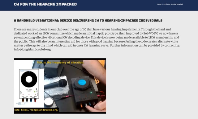 The resource details a novel approach to Morse code (CW) reception for hearing-impaired operators, focusing on a handheld device that translates CW signals into tactile vibrations. It explains how this device allows users to perceive the patterns of dots and dashes through physical feedback from a shaker, addressing the challenges of auditory discrimination for those with hearing loss. The content highlights the potential for this tactile method to aid in CW learning and interpretation, even suggesting benefits for operators with normal hearing by providing an alternative sensory input. The article also mentions the device's _patent-pending_ status and its availability to members of the _Long Island CW Club_ and the general public. It provides contact information for further inquiries about this innovative tool.
 -
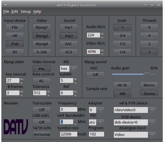 The ZL1WTT resource details an experimental software-based Digital Amateur Television (DATV) system, demonstrating the multiplexing of up to six standard-definition (SD) and one high-definition (HD) channel utilizing _h264 compression_. The author encountered peak data rates reaching 32 Mbit/s, necessitating a shift to Freeview and Sky settings (22.5M Sym/s 3/4FEC) to manage bandwidth. The setup employs four networked computers, with a laptop functioning as the multiplexer to re-code PIDs for various inputs, including looped MPEG2 playlists, MPEG2 encoder card input from a VCR, satellite feeds, and an off-air UHF receiver. The system highlights the inherent flexibility of the DVB transport stream, supporting diverse formats such as MPG2, h264, AC3, and AAC. A significant advantage of this software-defined approach is the absence of video quality degradation from stored MPEG2 files to the displayed output, coupled with the ease of reconfiguring settings for MPEG2 encoder cards (e.g., size, bit-rate, frame rate, video input, coding format) and satellite receiver cards (e.g., frequency, LNB volts, symbol rate, FEC). The author also discusses the development of a new graphical user interface (GUI) using _Gambas_ for Linux, aiming to simplify configuration for this DATV project. Specific hardware components mentioned include Hauppauge WinTV PVR-150 and Nova-S plus cards, with a focus on optimizing analog video input via Y/C (S-video) to minimize frequency roll-off. The resource also provides insights into data rates for HD (1080i) content, recommending 8 to 12 Mb/s for optimal performance. Software utilized includes _Ubuntu Studio 10.04_, WinFF, VLC, and TMPGEnc Editor, underscoring the project's reliance on open-source tools and a foundational understanding of LAN networks and DVB transport streams.
 -
 This page provides a detailed guide on the J-pole antenna, an end-fed half-wave antenna matched to the feedline by a quarter-wave transmission line stub. It covers the characteristics, construction materials, feeding options, and mounting considerations for optimal performance. The information is useful for hams or amateur radio operators looking to build and set up a J-pole antenna for improved transmission and reception.
 -
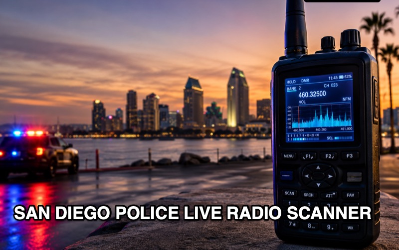 Monitoring public safety communications, particularly fire department dispatch, presents a unique challenge as agencies increasingly move towards encrypted systems. This Broadcastify feed, originating from a _BCD396XT_ scanner situated in northern San Diego City, provides real-time audio for the San Diego City Fire Department. While it previously included police dispatch, those transmissions are now fully encrypted, a common trend impacting scanner enthusiasts and emergency services observers alike. The setup utilizes a Windows server running _Freescan_ and _RemoteFS_ for remote control, ensuring consistent operation and clear audio via a ground loop isolator. With a peak of 8,785 listeners in the last 24 hours, the feed demonstrates significant interest in local emergency traffic. Alpha tags, indicating the current channel, are generally available for premium users, enhancing situational awareness for listeners. Feed archives are maintained in 30-minute segments, allowing for review of past incidents and operational patterns, a valuable feature for those studying emergency response or simply keeping informed about local events.