Search results
Query: side band
Links: 185 | Categories: 0
-
 Demonstrates the product line of _LZ Antenna Ltd._, a Bulgarian manufacturer specializing in amateur radio antennas and custom electronic devices. The company focuses on robust, high-quality HF multiband Yagi and vertical antennas, leveraging over 20 years of experience from founder Georgi Georgiev in radio amateur development. Featured models include the LZA 8-4, LZA-10-3, and the LZA-7-3A WRTC 2022, alongside various rotary dipoles like the LZA1 40/30m. Provides specifications for several Yagi antennas, such as the LZA-9-5, LZA-13-7, and LZA-6-3 (a 6-element, 3-band design). The company emphasizes applying "leading edge technology" to high-frequency communication equipment production, with products designed for durability and performance. The LZA-10-5 Yagi offers **12.5 dBi** gain on 10m, while the LZA-13-7 provides **13.2 dBi** on 20m, showcasing competitive gain figures for DXing and contesting.
 -
 Presents a construction project for a linear-loaded 40-meter rotatable dipole, detailing the design evolution from mid-element coils to 300-ohm twinlead loading. It covers material selection, including repurposed fishing poles and EMT conduit, and outlines the assembly process for the antenna elements and mounting plate. The resource provides specific measurements for element lengths and linear loading sections, along with SWR plots demonstrating the antenna's resonance at 7.035 MHz with a 1.1:1 SWR, and bandwidth up to 7.120 MHz below 2:1 SWR. The article documents the antenna's performance during various RTTY and CW contests, including the SARTG RTTY and SCC RTTY contests in August 2006, and the ARRL DX CW and CQWW WPX RTTY contests in February 2007. It reports successful operation at 500-1000W, noting improved performance after replacing a faulty coax cable. Specific DX contacts from British Columbia, including stations in Europe and South Africa, are listed, illustrating the antenna's capability despite its shortened length and relatively low height of 55 feet. The content highlights practical considerations such as weatherproofing the connections and supporting the fiberglass elements to prevent sagging. It also includes a brief comparison to an inverted-V at similar height and a ground-mounted vertical, noting the rotatable dipole's quieter reception. The author shares insights into the iterative design process and tuning adjustments made to achieve optimal resonance.
 -
 There is considerable confusion as to what exactly a multiband vertical antenna is. The confusion concerns the method of feed, how much mismatch one can expect, how many radials are required, how the particular antenna is built for multiband use, plus some other points.
 -
 With over 20 years of experience, Proyecto 4 operates as a specialized ham radio retailer in Madrid, Spain, providing a diverse inventory of transceivers, antennas, and related accessories. The store features popular models like the _ICOM IC-705_ and _ICOM IC-7300MK2_, alongside Yaesu transceivers such as the _FTX-1 Optima_, which delivers 100W on HF and 50W on V/UHF bands. The product range includes mobile and portable antennas, such as the D-Original DX-NR770HB, offering 3 dB gain on 144 MHz and 5.5 dB on 430 MHz, and the Diamond RH-770 with a BNC connector. CB radio enthusiasts can find the Anytone CB SMART II AM/FM transceptor and the Telecom LS145 mobile antenna, rated for 500W and 4 dB gain on 26-30 MHz. Proyecto 4 emphasizes its in-house technical service, inviting customers to visit their laboratory for repairs and technical consultations via sergio@proyecto4.com. The store also highlights customer reviews and offers promotions like Yaesu Cashback, providing savings up to 100€.
 -
 Presents the design and performance of a 4-element wire Yagi antenna for the 40-meter band, building upon VE3VN's earlier 3-element switchable wire Yagi. The resource details the antenna's evolution, highlighting the transition from a 3-element to a 4-element configuration and the resulting improvements in gain and front-to-back ratio. It provides specific insights into the antenna's construction and expected operational characteristics. VE3VN shares insights from field results, noting the antenna's performance on 40 meters. The discussion includes the antenna's pattern and matching characteristics, crucial for any DXer or contester looking to optimize their signal on this popular HF band. The author's experience with the previous 3-element design informs the enhancements made to this 4-element iteration. The article includes a visual representation of the antenna's current view, offering a practical perspective on its physical layout. It serves as a valuable reference for hams considering a directional wire antenna for 7 MHz operations, demonstrating a practical approach to achieving enhanced directivity and gain.
 -
 The 11-meter band, often associated with Citizens Band (CB) radio, presents unique challenges and opportunities for long-distance communication, particularly for operators interested in DXing. This group facilitates discussions and information exchange among enthusiasts who operate on this frequency, often utilizing single-sideband (SSB) modulation for improved range and signal clarity compared to traditional AM CB operations. The community provides a platform for members to share experiences, technical insights, and propagation reports relevant to 27 MHz operations. Members engage in discussions covering various aspects of 11-meter DX, including antenna configurations, transceiver modifications, and operating techniques to maximize signal propagation across continents. The forum serves as a central hub for coordinating contacts, sharing QSL information, and celebrating successful long-haul QSOs. Specific topics often include optimizing power output, reducing noise, and understanding solar cycle effects on 27 MHz. The group's activities extend to organizing virtual gatherings and promoting ethical operating practices within the 11-meter DX community. It supports both seasoned operators and those new to the band, fostering a collaborative environment for exploring the capabilities of CB radio beyond local communications.
 -
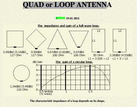 Quad and loop antennas comparisons, evaluating the impedance and gain of both antennas and considerationso n horizontal loop antennas for low bands by PA0FRI
 -
 Demonstrates the design and construction of a compact, portable multi-band mini-delta loop antenna, specifically optimized for /P (portable) operations from remote locations like Scottish islands. The resource covers the theoretical underpinnings of half-wave loops, contrasting closed and open configurations, and then details the application of a folded dipole principle to achieve a 50-ohm match for direct coax feed. It presents empirical formulas for calculating element lengths, considering the velocity factor of common wire types, and provides a detailed example for a 20m (14.175 MHz) version. The article includes a comprehensive table of dimensions and allowances for a five-band (20m, 17m, 15m, 12m, 10m) mini-delta beam, along with construction hints for the central support and balun. It specifies a 1:1 trifilar balun wound on a ferrite rod and describes the antenna adjustment process using an _MFJ-259B Antenna Analyser_. Initial test results indicate an SWR of 1:1 at resonance and a bandwidth of approximately 240 kHz on 20m, even at a low height of five feet above ground. The distinctive utility lies in its focus on a practical, easily deployable beam antenna for portable DXing, offering a viable alternative to more complex or larger arrays.
 -
 The document provides a detailed guide on modifying an inverted-L antenna to include the 160 meters band. This enhancement allows amateur radio operators to utilize the lower frequency effectively, which is crucial for long-distance communication, especially during the night. The inverted-L design is popular due to its compact size and ease of installation, making it suitable for various environments. By adding top band capabilities, operators can engage in DXing and contesting on 160m, expanding their operational range and opportunities. The guide includes practical tips and considerations for construction, ensuring that the antenna maintains its performance across the extended frequency range. It discusses the necessary adjustments and materials required for the modification, along with potential challenges and solutions. Whether you are a seasoned operator or a beginner, this project can enhance your station's capabilities, allowing for more versatile operations and improved signal quality on the 160m band.
 -
 Since February 2002, 3830scores.com has served as a central repository for amateur radio contest score rumors, allowing contesters to quickly post and view claimed scores and comments. The platform facilitates the sharing of **claimed scores** for numerous contests, including the ARRL DX Contest, CQ WPX RTTY Contest, and various QSO Parties. Users can access submittal forms for current and recent contests, with options to define and save default form values for efficiency. The site also provides links to the 3830 Reflector, where submissions are posted, fostering immediate community engagement regarding contest performance. Summaries of all submitted scores are instantly available, offering line scores, **band/mode breakdowns**, and compilations of operator comments. Historical summaries for major contests extend back to 2002, with all contest data accessible from 2007. The platform includes a search function to locate all postings associated with a specific call sign and a 'Compare Scores' feature, enabling side-by-side analysis of multiple calls across different contest editions or a single call's performance over several years.
 -
 Demonstrates the design principles and performance characteristics of **corner reflector antennas**, emphasizing their high gain and directional properties. It covers critical design factors such as the corner angle and the spacing between the radiating dipole and the reflector vertex. The resource explains how reducing the corner angle increases gain but lowers feed impedance, making matching more challenging. Practical angles of 90 degrees or 60 degrees are discussed, with 90 degrees offering easier impedance matching despite slightly lower gain. Details key design considerations, including reflector side length exceeding two wavelengths and reflector width greater than one wavelength for a half-wave radiator. It specifies reflector construction using wire netting, sheet metal, or parallel metal spines spaced less than 0.1 wavelength. The article provides a table with general dimensions for UHF and VHF bands, noting typical impedance values of 50 to 75 ohms and expected SWR of 1.7:1 on the lower band edge. Adjustable radiator-to-vertex spacing is highlighted as crucial for final tuning.
 -
 Homebrew a cobwebb antenna for the HF bands. This page describe a cobwebb multiband antenna resonating on 14 18 21 24 and 28 MHz. The cobweb antenna model can be considered a fan dipole, or better, multiple dipoles fed in parallel.
 -
 The G5RV multiband HF antenna, designed by Louis Varney (G5RV) in 1946, is a popular compromise antenna offering good overall performance on most HF bands when paired with an external antenna tuner. The basic full-size G5RV measures 102 feet across the top for 80 through 10 meter operation and is fed at the center via a 34-foot low-loss feed-stub. This interaction between the radiating section and the feed-stub facilitates matching across 80-10 meters with a standard tuner, often eliminating the need for ladder line directly to the shack. The antenna's design center frequency is 14.150 MHz, configured as a 3/2-wave dipole on 20 meters, with its 102-foot length derived from long-wire antenna formulas. Construction details emphasize the matching section, which can be open wire, ladder line (window-type), or TV twin lead. Each type has a specific velocity factor (VF) affecting its physical length for an electrical half-wave on 14 MHz; for instance, open wire requires 33.7 feet (VF 0.97), ladder line 31.3 feet (VF 0.90), and TV twin lead 28.5 feet (VF 0.82). The article provides formulas for calculating these lengths and discusses the antenna's behavior on individual bands, from 3.5 MHz where it acts as a shortened dipole, to 28 MHz where it functions as two three-half-wave long-wire antennas fed in-phase. Practical construction notes include recommendations for vertical descent of the matching section, sealing the coax junction, providing strain relief, and winding a coaxial choke coil to mitigate common mode current. The resource also presents dimensions for double-size (204 ft) and half-size (51 ft) G5RV versions, along with their corresponding matching section lengths for various line types, making it a versatile reference for hams considering this classic wire antenna.
 -
 This antenna is designed to be mounted off the side of a tower. Works on 136-153 Mhz range but also on 70 cm band
 -
 Presents a QRP AM/CW transmitter project specifically designed for the 10-meter band, utilizing a crystal oscillator and a collector-modulated AM oscillator. The design employs a 2N2219(A) transistor in a Colpitts configuration, generating 100 to 350 mW of RF output power depending on the 9-18 Volt supply voltage and modulation depth. Frequency stability is maintained by a 28 MHz crystal, with fine-tuning possible via a Ct1 trimmer capacitor for approximately 1 kHz adjustment. The resource details the RF oscillator stage, implemented with a 2N2219 NPN transistor, emphasizing frequency stability and low power dissipation. It also covers the amplitude modulation stage, managed by a 2N2905 PNP transistor, which impresses audio information onto the carrier. Selective components (C3, C4, C7, C5) enhance voice frequencies within a +/- 5 kHz bandwidth, and modulation depth is controlled by R2 and R3. The project includes a 3-element L-type narrow bandpass filter (Ct3, L3, C10) to suppress harmonics and ensure a clean output signal. The project provides a complete schematic diagram, a comprehensive parts list including specific capacitor, resistor, and inductor values, and construction notes for the coils (L1, L2, L3). It also offers practical advice on enclosure requirements, suggesting an all-metal case or a PVC box with graphite paint for RF shielding. Operational parameters such as current draw (27mA@9V to 45mA@16V) and input impedance (50 Ohms) are specified, alongside guidance on antenna matching and the importance of a valid amateur radio license for 10-meter band operation.
 -
 The antenna is a VHF side is a 2m moxon, tuned on 145.825 MHz. The driven element of the moxon couples to a driven element for a 5 element 70cms Yagi, tuned on 436.5 MHz.
 -
 Operating on the 2200m band (135.7-137.8 kHz) often presents challenges for amateur radio transceivers, which typically exhibit poor receiver performance at these very low frequencies. This project addresses the issue by providing a design for a dedicated 137 kHz antenna preamplifier, specifically tailored to improve signal reception for radios such as the _Yaesu FT-817_. The preamplifier circuit utilizes a low-noise FET input stage, crucial for minimizing self-generated noise and maximizing the signal-to-noise ratio from weak LF signals. The design includes a detailed schematic, component values, and construction notes, enabling homebrewers to build a functional unit. The goal is to achieve significant gain, making the faint signals on 2200m more discernible and improving overall band usability. Key design considerations include impedance matching to typical antenna systems and ensuring stable operation across the narrow LF segment. The circuit aims for a **low noise figure** and sufficient amplification to overcome the inherent limitations of general-purpose HF transceivers when operating below **200 kHz**.
 -
 This project details the construction of a **full-sized 40-meter vertical antenna**, born from a renewed interest in 7 MHz operation and a desire for improved effectiveness over simple dipoles. The author, K5DKZ, initially focused on VHF experimentation, which provided an inventory of aluminum tubing and fiberglass spreaders for this endeavor. Before this vertical, K5DKZ utilized an 80/40 meter inverted-vee trap dipole and a 40-meter broadband dipole, but now primarily uses a pair of full-sized, phased, quarter-wave verticals spaced 35 feet apart for serious 40-meter work. The construction involves a base-heavy design for stability, using a 44.5-inch section of 1-1/4 inch steel TV mast driven into 1-3/8 inch aluminum tubing, insulated by a 105-inch section of Schedule 40 PVC pipe. The assembly reaches 31 feet, close to the 32 feet required for a quarter-wavelength on 40 meters, with fine-tuning achieved by winding wire onto a fiberglass spreader. The design is explicitly presented as a foundation for a two-element 40-meter Yagi beam, outlining modifications like substituting aluminum for steel in the base and using an inductive hairpin match for the driven element. The article also discusses tuning considerations for a large 40-meter beam, noting the 100 to 200 kHz upward frequency shift when raised, and suggesting methods for installation on a tower. The author emphasizes the cost-effectiveness and good performance of the monopole approach, especially when multiple verticals are needed.
 -
 The grounded half loop describe in this article is basically a half wave length wire on 80 Meters. The 80M grounded half loop antenna, inspired by a 1984 QST article by SM0AQW, is a compact solution for limited spaces. Comprising a 127-foot wire fed against ground and supported by radials, it balances performance and practicality. Despite compromises in length and proximity to structures, the antenna delivers strong signal reports and effective multi-band tuning using an SGC 237 antenna coupler. Ideal for CW operation, it offers low SWR on 80-10M, though noise levels and safety considerations warrant attention. This versatile design excels in constrained environments.
 -
 An Unorthodox Antenna, originally by W3AWH is considered a multi-band antenna suitable for fixed location use and as an easily deployable portable antenna for events such as Field Days.
 -
 The Yaesu FT-1000MP Mark-V, introduced at Dayton 2000 Hamvention, features a higher RF power of **200 W PEP** and a Class-A amplification SSB mode at 75 W. Key enhancements include an _Interlocked Digital/Analog Bandwidth Tracking system (IDBT)_, a Variable Front-End Filter (VRF) preselector, and improved ergonomics, notably a multi-function shuttle jog dial. This model, a successor to the 1996 FT-1000 and FT-1000MP, was designed to compete with high-end transceivers, despite its retail price of $4200 initially. The transceiver's physical dimensions are 406 x 135 x 348 mm (16 x 5.3 x 13.7 inches) with a weight of 14 kg (31 lbs), making it substantial. Its rear panel offers over 20 connections, including power, external DSP speaker, BAND DATA I/O, ALC, and multiple interface jacks for DVS-2, Packet, and RTTY. The unit also provides two keyer inputs, a DB9M serial interface for CAT, and two PL female antenna connectors, plus additional receive antenna jacks. Despite its advanced internal architecture, including two independent receivers with their own IF filters and AGC loops, the display technology, utilizing fluorescent discharge rather than LCD, contributes to an older aesthetic. The control panel is extensive, featuring 92 knobs and buttons, alongside numerous LED indicators for various modes and functions.
 -
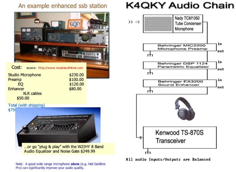 Enhanced SSB Audio (ESSB) is a specialized operating mode that extends the capabilities of traditional Single Sideband (SSB) voice transmissions. This presentation by K4QKY delves into the technical aspects of ESSB, discussing its advantages and the ongoing debates within the ham radio community regarding audio quality and bandwidth usage. ESSB aims to provide clearer and more natural-sounding audio, which can enhance the overall communication experience for operators. The presentation covers various topics, including microphone selection, audio processing techniques, and the importance of proper equalization. It also addresses the controversies surrounding ESSB, such as the potential for interference and the debate over whether it strays too far from traditional SSB practices. By understanding these elements, amateur radio operators can make informed decisions about their audio setups and contribute to discussions about the future of SSB operations.
 -
 A three band short Vee antenna is feasible with two legs per side on a dipole. 10-15-20 meters by W8HDU
 -
 The ZS6BKW multi-band antenna, an optimized variant of the classic G5RV, is presented with detailed construction and tuning instructions. This resource outlines the antenna's design principles, which were developed by _Brian Austin (G0GSF)_ using computer programs and Smith charts to achieve optimal dimensions. It provides specific guidance on calculating and adjusting the lengths of the radiators (L1) and the matching ladder line (L2), emphasizing the critical role of velocity factor (VF) in achieving resonance. The article includes a step-by-step procedure for empirically determining the VF of ladder line using an antenna analyzer, ensuring accurate physical lengths for the matching section. It details the tuning process for the radiators, offering practical tips for incremental adjustments to achieve the best SWR curve. The resource presents SWR measurement results obtained with an _AIM-4170C_ analyzer across multiple bands, alongside predicted SWR graphs from an AutoEZ model. It confirms successful contacts on 80, 40, 20, and 17 meters, including a **17-meter DX contact** to Italy. EZNEC and AutoEZ models for the ZS6BKW antenna, covering 80 through 6 meters, are provided for download, allowing further analysis and customization. The document specifies component details, such as the use of Wireman 554 ladder line and #14 AWG THHN copper wire, and discusses the antenna's performance characteristics, noting high SWR on 15 and 30 meters but successful tuning on 6 and 80 meters with an external tuner.
 -
 The resource details the construction of a homebrew 50-watt FET amplifier, based on Don W6JL's _QST Homebrew contest_-winning design from 2009. It functions as an afterburner for QRP transceivers, providing a **12dB** power lift. The amplifier utilizes IRFZ24N FETs and covers the 80, 40, 30, and 20-meter bands, with the 20m LPF extending to 17m. Key technical aspects include an FT37-43 transformer for the input network, a relay-switched 3dB pad for lower bands controlled by an _Arduino Nano_, and an RF-actuated T/R switch. The LPF board integrates four relay-switched filters rated for 50 watts, using capacitors with a minimum 250VDC rating. Performance measurements indicate a power gain ranging from **4.4dB** on 20m to 8.1dB on 80m, with a required drive power of approximately 5 watts. The article also discusses thermal management, current limiting considerations, and component sourcing.
 -
 The main function of the Ugly Balun is to help eliminate rf currents from flowing on the outside of coaxial cable using the principle of choke action.
 -
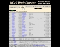 The NG7M Web Cluster, maintained by W7CT and NG7M, offers real-time DX spotting information crucial for amateur radio operators engaged in DXing and contesting activities. This service aggregates DX spots from various sources, presenting them in a user-friendly format accessible via both web interface and traditional telnet protocols. Operators can monitor band conditions, identify rare DX entities, and track propagation paths across multiple amateur radio bands. This cluster supports a wide range of operating modes and bands, facilitating efficient station operation for both casual DX chasers and serious contesters. The system integrates data from the Reverse Beacon Network (RBN) and PSK Reporter, enhancing its utility by providing automated CW and digital mode spots alongside manually entered voice spots. Access methods include a direct web interface for graphical display and a telnet connection for command-line interaction, catering to different operational preferences. The cluster's data stream is continuously updated, ensuring timely information for making critical operating decisions.
 -
 Designing and constructing portable wire antennas for HF operations, this resource explores several configurations including the _foldback dipole_ for space-constrained setups and an inductively shortened dual-band dipole for 20m and 40m. It details the calculation of inductance for shortened elements, providing a Visual Basic 6.0 program screenshot that illustrates determining coil parameters like turns and length for a **25.5 uH** inductor. The document emphasizes practical considerations such as adjusting wire lengths for optimal SWR, noting that a dual-band dipole achieved SWR below 2:1 on both 20m and 40m, with careful adjustment bringing it under 1.5:1. Further, the resource describes a half-wave antenna matched with a coaxial stub, a method often referred to as the _Fuchskreis_ in German amateur radio circles, to transform the high feedpoint impedance to 50 Ohms. This monoband solution, for a 20m application, uses a stub length of **2.98m** (0.216 lambda multiplied by coax velocity factor) and a shorted stub of approximately 48cm. The coaxial stub design is highlighted for its resilience to ground proximity, allowing it to be rolled up or laid on the ground with minimal SWR impact, making it highly suitable for portable QRP operations.
 -
 The page discusses the concept of a 2-element Parasitic Ground Plane antenna for the 40-meter band. It includes a conversation between amateur radio operators discussing modeling results and design considerations for the antenna. The author shares insights on radial configurations and the impact on antenna efficiency and pattern.
 -
 The **KC0KJF** personal amateur radio page provides a collection of resources for fellow hams, particularly those interested in operations within southwest Missouri. It offers detailed listings for **Missouri repeaters** on both 2 meters and 70 centimeters, serving as a practical reference for local VHF/UHF communication. The site also includes information about the operator's station setup and antenna projects, such as a dipole and a bazooka antenna, which can offer insights into basic antenna construction and deployment. Beyond local repeater data, the page features links to the FCC Part 97 rules, essential for understanding amateur radio regulations. The operator, licensed as a Technician Class since April 16, 2001, shares his journey from Citizen's Band Radio to amateur radio, driven by a lifelong fascination with shortwave listening. This narrative provides context for the resource's focus on practical operating information and foundational regulatory knowledge. Additional content covers specific equipment like the 2-meter/70-centimeter Arrow Antenna, useful for hams considering portable or fixed station VHF/UHF setups.
 -
 The **Solarcon A99** vertical antenna, a half-wave over a quarter-wave variable mutual inductance design, primarily serves the 11-meter CB band but also finds use on 10 and 12 meters for amateur radio operators. Its simple construction, consisting of three fiberglass sections and a 16 AWG radiating element, makes it an accessible option for new operators or those seeking an easy-to-install base station antenna without complex mounting requirements. Despite claims of 9.9 dBi gain being widely considered exaggerated, and a manufacturer rating of 2000 watts power handling often viewed with skepticism (with 300 watts suggested as a practical limit), the A99 maintains popularity due to its low cost and ease of deployment. It typically tunes to a 1.2-1.3 SWR out of the box, requiring minimal adjustment via its two tuning rings. Its high angle of radiation allows for effective local communication even when mounted at low heights, such as 8-10 feet off the ground. However, the A99 is known for significant RF bleed-over issues, particularly when operated with higher power or mounted close to residential electronics. While its internal design is often described as cheap, the antenna exhibits remarkable durability, frequently lasting a decade or more in various weather conditions. Its affordability and straightforward setup continue to make it a go-to choice for many radio enthusiasts.
 -
 This is a group for CBers, Sidebanders, Amateurs and Freebanders. Items to be discussed are CB, Skip, Skeds, DX communications, SSB, export radios, Radio equipment, mods, ham radio, repairs, electronics, CW, PSK31, RTTY, digital, and different radio shops.
 -
 Optimizing weak signal reception on the HF bands, particularly in the presence of strong local QRM, often necessitates specialized receiving antenna systems. This resource details the _HI-Z Antennas_ product line, focusing on phased vertical arrays designed for superior noise rejection and directivity. It covers components such as the 4-Square and 8-Element array controllers, which allow for rapid switching of receive patterns, and dedicated low-noise preamplifiers to improve system sensitivity. The site also presents various bandpass filters, crucial for mitigating out-of-band interference and enhancing the dynamic range of the receiver. The HI-Z systems are engineered to provide significant front-to-back and side rejection, often yielding **20-30 dB** of attenuation to unwanted signals, which is critical for DXing and contesting. Users can achieve a notable reduction in local noise, allowing for the discernment of signals that would otherwise be buried. The array controllers facilitate quick pattern changes, enabling operators to null out interference or peak weak signals from distant stations, effectively extending the reach of their receive capabilities by improving the signal-to-noise ratio.
 -
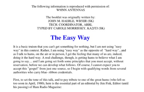 This document is a must read for anyone considering building a good low cost HF multi-band antenna system. The author combine in this document four important ingredients to produce simple but effective antenna system, like antennas of non resonant length, line attenuation, the transmatch and the balun
 -
 The TransWorld Antennas TW4040 The Adventurer Monobander™ is a portable HF antenna designed for rapid deployment in field operations, including **SOTA** and **POTA** activations. This manual details the antenna's assembly, tuning procedures, and operational guidelines for optimal performance on the 40-meter band. It outlines the specific components, such as the telescoping whip and base unit, required for proper setup. Instructions cover mast erection, radial wire deployment, and impedance matching to achieve a low **VSWR** across the designated frequency segment. The document also provides guidance on antenna orientation and environmental considerations for portable use. It specifies the antenna's power handling capabilities and physical dimensions when fully deployed and collapsed for transport.
 -
 An interesting presentation of a real multiband Fan Dipole antenna, optimized for better DX operation performances, considering the terrain, position, DX destination path and other influencing factors
 -
 The dipole shown in this document is installed in an inverted Vee configuration, with two leg elements on each side held parallel to each other by 21cm spacers. The upper leg is for 40m and the lower leg for 20m. The spacers are made of 7mm plastic garden hose support for garden sprayers cut to 21cm.
 -
 The BTech DMR-6X2 dual-band DMR handheld radio is thoroughly reviewed, detailing its features and performance for amateur radio operators. This resource covers the radio's capabilities for both VHF and UHF frequencies, supporting Tier II DMR digital and FM analog modes. It highlights key specifications such as its **136-174 MHz** and **400-480 MHz** frequency ranges, CTCSS/DCS, DTMF, 2-TONE, and 5-TONE signaling, and its _digital simplex repeater_ function. The review provides a comprehensive unboxing experience, listing included accessories like two Li-Ion batteries (2100 and 3100 mAh), a programming cable, and a 37-page English user guide. It also specifies the radio's physical dimensions of 5.1 x 2.4 x 1.5 inches and weights of 9.9 oz with the 2100 mAh battery and 10.8 oz with the 3100 mAh battery, offering practical insights for hams considering this transceiver.
 -
 Constructing a compact directional antenna for the 17-meter band, this resource details the build process for a Moxon rectangle, a two-element Yagi variant with folded-back elements. It covers the antenna's evolution from the _VK2ABQ beam_ and provides specific dimensions for a version built using fishing pole whips. The content includes a discussion of the antenna's radiation pattern, feedpoint impedance, and its inherent front-to-back ratio, which is often superior to a standard two-element Yagi. Practical considerations for element spacing and material choices are also addressed, alongside a visual representation of the antenna's physical layout. Performance data presented includes a comparison showing the Moxon rectangle's **2.5 dB gain** over a half-wave dipole and a front-to-back ratio of **20 dB**. The resource also touches upon the antenna's relatively wide bandwidth for a two-element beam and its suitability for portable operations due to its compact footprint. It offers insights into optimizing the design for specific operating conditions and discusses the advantages of its lower take-off angle compared to omnidirectional wire antennas, making it effective for DX contacts on the 17-meter band.
 -
 The Superantennas MP-1 portable HF antenna is analyzed for its design and field performance, particularly its high-Q loading coil and 3/8-inch mounting. The review details the antenna's construction, including an 8-inch vertical section, a large-diameter loading coil tuned by a sleeve, and a 4-foot whip that disassembles into six rods for transport. Initial testing with the supplied 10-foot ribbon cable "ground plane" yielded poor SWR and RF hot conditions, indicating an inadequate ground system. Further experimentation with longer radials and resonant counterpoises for each band improved matching and eliminated RF hot issues, but introduced significant operational complexity. The author notes the difficulty in optimizing both counterpoise length and coil setting without an antenna analyzer, and the sensitivity of the MP-1 to counterpoise deployment. The review also discusses the recommendation to tune for maximum received signals rather than minimum SWR, often necessitating an external ATU due to the antenna's typical low impedance. The **MP-1**'s critical dependence on resonant counterpoises for effective operation, especially when elevated, is highlighted as a major drawback for portable use. The author ultimately sold the antenna, concluding that despite its sound technical design, its fussy nature and the need for extensive counterpoise management or an ATU detract from its portability and convenience compared to simpler, less expensive dipole solutions. The **Superantennas MP-1** is deemed a flawed portable antenna, requiring considerable effort to achieve its claimed performance.
 -
 This wire antenna for 40 and 20 meter band feature a good SWR. Horizontal side of the antenna is placed at two meters above the ground. Impedance of the antenna are depending by the height of the base from the ground and conditions of the ground
 -
 BeaconSpot.uk provides an accurate, real-time picture of microwave and VHF/UHF beacons operating across Europe, alongside a worldwide listing of 6-meter beacons. The platform allows users to retrieve detailed data for individual beacons, facilitating in-depth analysis of signal characteristics and propagation paths. Interactive maps visualize beacon distribution by frequency band and display spot coverage for each station, offering a clear geographical overview of active beacons. The system integrates real-time DXCluster spots, sourced from contributors like Alain, ON4KST, and Pascal, F5LEN, and enables users to submit outgoing spots directly to the DXCluster. Beacon keepers can manage their beacon data, receive email alerts upon being spotted, and track their station's ODX (Outstanding DX) records. For every received spot, the distance to the beacon is automatically calculated and displayed, aiding propagation studies.
 -
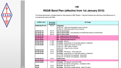 The RSGB Band Plan is normally published annually in the February edition of RadCom and additionally reviewed mid-year. It is derived from the IARU Region 1 Band Plan taking into account any proposed national variations or special amendments, which are considered necessary by the relevant spectrum manager.
 -
 The article, "Using 75 Ohm CATV Coaxial Cable," details methods for employing readily available 75-ohm CATV hardline in standard 50-ohm amateur radio setups. It addresses the inherent impedance mismatch and practical considerations, such as connector compatibility, for hams seeking cost-effective, low-loss feedline solutions. The resource specifically contrasts common 50-ohm cables like RG-8, RG213, and _LMR-400_ with 75-ohm hardline, highlighting the latter's lower loss characteristics, particularly at VHF and UHF frequencies. It explores two primary approaches to manage the impedance difference: direct connection with an acceptable SWR compromise and precise impedance transformation. The direct connection method acknowledges that a perfect 1:1 SWR is not always critical, especially when using low-loss coax. For impedance transformation, the article explains the use of half-wavelength sections of coax to reflect the antenna's 50-ohm impedance back to the transmitter, noting its single-frequency effectiveness. It also briefly mentions transformer designs using toroid cores and a technique involving two 1/12 wavelength sections of feedline for broader bandwidth. The content further clarifies the concept of _velocity factor_ for calculating electrical versus physical cable lengths, providing a generic formula for precise length determination. It notes that while half-wave matching is practical for 10 meters and above, it can result in excessively long runs for lower bands like 160 meters, potentially adding **250 feet** of cable. The article also mentions achieving a usable bandwidth of 28.000 MHz up to at least **28.8 MHz** on 10 meters with specific transformation techniques.
 -
 A synthesized 2.3 GHz Amateur Television (ATV) transmitter design, conceived by Ian G6TVJ, is presented, targeting broadcast-quality video performance on the 13cm band and extending up to 2.6 GHz. The core of the design utilizes a commercial Z-comm Voltage Controlled Oscillator (VCO) that tunes from 2.2-2.7 GHz, providing a +10 dBm output and simplifying RF alignment. This VCO's stability, originally intended for narrowband applications, readily accepts high-frequency video modulation, contributing to the transmitter's robust performance. The exciter stage, incorporating a Mini Circuits VNA 25 MMIC amplifier, boosts the signal to +16dBm, while a Plessey SP4982 prescaler divides the output frequency for the synthesizer. The synthesizer employs a Motorola MC145151 CMOS parallel IC, favored over the common Plessey SP5060 for its superior video modulation characteristics and ease of programming without microprocessors. This choice addresses issues like LF tilt and distorted field syncs often seen with SP5060 designs, particularly when operating through repeaters or over long distances. The MC145151 divides the signal further, enabling precise frequency stepping, with programming handled by EPROMs for channel selection and LED display. The loop filter network, critical for video integrity, was developed through experimentation to prevent the PLL from reacting to video modulation, ensuring a clean transmitted picture. The transmitter incorporates a Down East Microwave commercial power amplifier module, delivering approximately 1.6W output, driven by the exciter through a 3dB attenuator. Construction involves surface-mount SHF components on micro-strip lines etched onto double-sided fiberglass board, housed within a tinplate box. The design boasts no AC coupling in the video path, preserving low-frequency response, a common failing in other ATV transmitters. Performance tests with a 50Hz square wave revealed no LF distortion, and a calibrated "Pulse & Bar" signal showed a near 100% HF response, demonstrating its capability for high-quality ATV transmissions.
 -
 Evaluates the **LDG Z100 autotuner**, a device designed to automatically match antenna impedance for optimal transmission efficiency. The review discusses its performance in comparison to the MFJ-902, noting that while the Z100 is a reliable autotuner, it does not match the range of impedances that the MFJ-902 can handle. The Z100 is suitable for operators seeking a 100-watt autotuner that covers HF bands, providing a practical solution for those who require automatic tuning without manual adjustments. The review highlights the Z100's operational context, focusing on its use in HF bands and its practical application in amateur radio setups. While it offers a straightforward tuning process, the Z100's limitations in impedance matching are noted, making it less versatile than some competitors. This comparison provides valuable insights for operators considering an upgrade or replacement for their current autotuner. The Z100's performance is positioned within the broader market of autotuners, offering a clear perspective on its strengths and weaknesses in real-world amateur radio operations.
 -
 Demonstrates the complete design and development process for a **Low Noise Microwave Amplifier** (LNA), beginning with conceptual design and progressing through prototyping. The tutorial series covers the initial stages of a single-ended first gain stage, focusing on critical parameters such as noise figure, gain, and stability. It systematically details the theoretical underpinnings and practical considerations for achieving optimal performance in microwave frequency applications. This resource provides a structured approach to LNA construction, enabling radio amateurs and RF engineers to understand the iterative steps involved in realizing high-performance receive-side amplification. It offers insights into component selection, impedance matching networks, and the measurement techniques required to validate design specifications, particularly for **microwave** band operation where noise performance is paramount.
 -
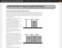 Fundamentals of operating on single sideband
 -
 A monoband delta loop antenna for the 7 MHz. This vertically polarized DX Antenna is a full wavelength sngle side antenna and has a total length of 42.3 meters (137,1 inch) Can be easily setup with a flag pole or fishing pole as center top mast. For optimal performance lower side should be at 2 meter above the ground. This antenna offers a low radiation angle and 1 DB Gain.
 -
 Antenna Authority Inc. offers a wide assortment of directional, wideband antennas and other equipment specifically engineered for radio direction finding (DFing) and geolocation applications. Their product line includes _log periodic_, _cavity-backed spirals_, and _Yagi_ antennas, alongside covert antenna solutions for various operational requirements. The company emphasizes its expertise in designing and manufacturing specialized antennas for both overt and covert operations. Beyond standard offerings, Antenna Authority Inc. provides custom design services to meet specific client needs, focusing on tailored RF directional products. Their capabilities extend to developing antennas for vehicles and optimizing their operational performance in diverse scenarios. The firm is located at 3381 W. County Line Road, Douglasville, Ga. 30135-1145. Ferrel Bentley is associated with Antenna Authority Inc., which has been operating since at least 2005, as indicated by the copyright notice.