Search results
Query: transmit ant
Links: 166 | Categories: 4
-
 The 10-minute, 25-second video demonstrates making a QSO via the VO-52 amateur radio satellite, focusing on real-time Doppler shift correction. It features Simon, 2E0HTS, operating a Yaesu FT-847 transceiver and a homebrew dual-band Yagi antenna, specifically a 10-element 435 MHz Yagi for uplink and an IO Loop for 145 MHz downlink. The video visually details the operator's technique for continuously adjusting the uplink frequency to compensate for the satellite's changing velocity relative to the ground station, a critical aspect of successful satellite communication. The demonstration highlights the practical application of Doppler compensation, showing the operator tuning the transmit frequency to maintain a stable received signal from the satellite. This approach contrasts with systems employing automatic Doppler correction or full-duplex operation, providing insight into manual frequency management for satellite passes. The video serves as a direct, observational guide for hams interested in LEO satellite operations, particularly those using non-tracking, manually tuned setups.
 -
 Demonstrates various practical amateur radio projects and technical discussions through video episodes. One episode details cutting and retuning a _1/4 wave shorted stub_ from 101.7 MHz to 107.5 MHz to safeguard a transmitter's driver stage, alongside insights into advanced _160-meter antenna systems_ like eight-circle arrays and beverage antennas. Another segment covers upgrading firmware on an _ATS-20+_ receiver using AverDudes for improved display and functionality, and a detailed guide on using D-Star DR mode on an _ICOM ID-52A_ for international repeater programming. Additional content includes a deep dive into _OpenHamClock_ as a potential replacement for the HamClock project, updates on _Raspberry Pi 5_ running Trixie OS, and a review of the Choyong LC90 Internet radio with AI integration. The series also features "Ham College" episodes, which meticulously prepare viewers for the Technician Exam by covering topics such as antenna and transmission line measurements, SWR interpretation, and the functions of basic electronic components like rectifiers, relays, and transistors. Practical advice on coaxial cable characteristics, dummy loads, and proper soldering techniques is also provided.
 -
 Demonstrates the operational status and reception reports for the SK6RUD/SA6RR QRPP beacons, which transmit on 478.9 kHz, 1995 kHz, 10.131 MHz, and 40.673 MHz. These beacons utilize extremely low power, with the 630-meter beacon operating at approximately 0.1 watt ERP into an L-antenna, showcasing the potential for long-distance contacts under favorable propagation conditions. The site details the specific frequencies and antenna types employed, such as a vertical at 500 kHz and a 1/4 vertical for higher bands. The resource compiles over 10,530 reception reports from amateur radio operators worldwide, logging details such as date, time, band, RST signal report, locator, distance, and receiver setup. Notable long-distance reports include a 500 kHz reception by AA1A-Dave from 5832 km in 2008 and a 10.133 MHz reception by ZL2FT-Jason from 17680 km in 2010, illustrating the global reach of these low-power transmissions. Each log entry provides specific equipment used by the reporting station, including transceivers like the Yaesu FT817, ICOM IC-7300, and various antenna configurations such as coaxial mag loops, inverted Ls, and end-fed wires. The primary objective of the SK6RUD beacons is to challenge conventional notions of power requirements for effective two-way communication, proving that contacts over significant distances are achievable with minimal output. The site also includes a submission form for new reception reports, fostering community engagement and continuous data collection on propagation phenomena across different bands. The detailed logs offer practical insights into real-world propagation characteristics and the efficacy of QRPP operations.
 -
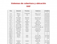 Presents a comprehensive listing of VHF and UHF repeater systems operating within Ecuador, detailing their operational frequencies and geographical coverage. The resource includes specific entries for locations such as _Guayaquil_, Cuenca, and Manta, alongside their respective frequency pairs. For instance, the Cerro Azul repeater in Guayaquil operates on **6.760- T**, indicating a transmit offset, while the Sta. Elena system utilizes a 26.660 MHz transmit frequency. The data provides essential information for local and visiting amateur radio operators seeking to utilize regional repeater infrastructure. It delineates coverage areas using two-letter provincial abbreviations, such as AZ for Azuay and GY for Guayas, facilitating route planning and mobile operation. This compilation is particularly useful for those engaged in local communications or emergency preparedness within the Ecuadorian amateur radio community, offering a practical guide to available repeater assets.
 -
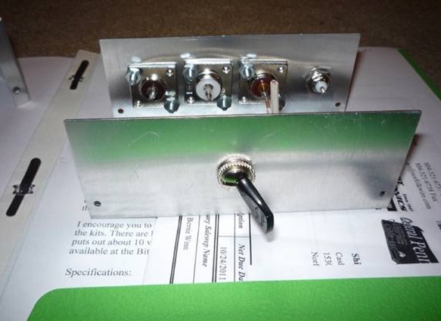
 A system designed to automatically tune small transmitting magnetic loop antennas, particularly beneficial for **contest operations** where rapid frequency changes are common. The core of the system involves a PC-based control application, AutoCap, written in C#, which monitors antenna SWR via an external meter and commands a motor interface to adjust the loop's variable capacitor. The software is compatible with Windows and Linux via the Mono framework, offering a graphical user interface for monitoring system status, SWR, power, and motor commands. Key components include one or more magnetic loop antennas equipped with DC or stepper motors for capacitor adjustment, an SWR meter with data output (such as the Telepost LP-100A or a homebrew serial/USB SWR meter), the AutoCap PC software, and a motor interface. The most effective motor interface utilizes an **Arduino-based controller** with custom firmware, providing precise control over both simple DC motors and stepper motors, and supporting features like motor braking for finer adjustments. The system allows for configurable SWR thresholds, pulse widths, and motor effort settings to optimize tuning speed and resolution. Optional radio integration provides frequency hints, enabling the algorithm to learn the relationship between motor actions and resonant frequency, thereby speeding up initial tuning responses. The software also supports antenna profiles, allowing operators to save and recall specific configurations for different loops, including accumulated frequency hint data.
 -
 Antenna tuners are crucial for matching the impedance of antennas to the 50 ohm output impedance of transmitters. The _LDG Z-11 Pro_ is an automatic antenna tuner designed to handle up to 125 watts, making it suitable for a wide range of amateur radio applications. Its compact form factor allows it to pair well with transceivers like the _FT-857D_, providing a portable solution for operators who frequently change locations or setups. The tuner covers the 80 through 6 meter bands, offering a broad impedance match capability. Although it struggles with some loads, it performs well with typical ham antennas, even managing to load an 80 meter dipole on 6 meters. One of the standout features of the _Z-11 Pro_ is its 8000 memory slots, which enable it to remember successful matches and quickly retune when revisiting frequencies. This memory function significantly reduces tuning time, often to less than half a second. The unit is well-constructed, with improved pushbuttons and a sturdy metal case that offers good shielding. However, users should be aware of potential RFI issues and the lack of a power switch, which requires disconnecting the power cord to turn off the unit completely. Overall, the _LDG Z-11 Pro_ is a user-friendly and cost-effective tuner, offering advanced features that enhance its utility in various amateur radio setups.
 -
 The 2000 CQ WW Multi-Multi operation by the GM0B contest group from Benbecula, Outer Hebrides, Scotland, is documented, providing insights into a significant **DX contest** effort. This resource outlines the station setup, operational strategies, and team composition for a large-scale, multi-operator, multi-transmitter entry. It details the logistical challenges and technical solutions employed to achieve competitive results from a remote island location, a common scenario for **DXpedition**-style contest operations. The page offers a glimpse into the practical application of contest rules and the coordination required for a successful multi-operator effort. It serves as a historical record of the GM0B team's performance in a major international contest, allowing other contesters to compare operational approaches and understand the scale of such an undertaking. The information can be useful for those planning similar contest expeditions or studying past contest strategies.
 -
 The early 20th century saw significant advancements in wireless communication, culminating in the first successful transatlantic radio signal. This historical account details Guglielmo Marconi's pioneering efforts, from his initial experiments with electromagnetic waves to his patented wireless system in 1900. It describes the technical challenges of long-distance radio transmission, particularly the prevailing belief that radio waves would be lost due to the Earth's curvature over vast distances. On December 12, 1901, Marconi established a receiving station in Newfoundland, Canada, utilizing a _coherer_ and balloons to elevate the antenna. Signals, consisting of the Morse code letter "S" (pip-pip-pip), were transmitted from Poldhu, Cornwall, England. The successful reception of these faint but distinct signals across **1,700 miles** confirmed Marconi's theories, marking an epoch in communication history. This achievement demonstrated the viability of global wireless communication, paving the way for future developments in radio technology.
 -
 Hi-Z Antennas offers specialized high-impedance receiving systems, primarily focusing on phased vertical arrays for HF reception. Their product line includes preamplifiers designed for shortened vertical antennas, featuring optimized 15dB gain and array-matched characteristics. These components are engineered to enhance weak signal reception and improve signal-to-noise ratio across the HF spectrum. The company provides controllers for managing multiple vertical elements in a phased array configuration, enabling directional reception patterns. These systems are particularly effective for mitigating local noise and interference, a common challenge in urban and suburban operating environments. Specific offerings include solutions for 160-meter and 80-meter bands, addressing the unique requirements of low-band DXing. Technical details often reference components like the 2N3866 transistor in preamp designs and discuss concepts such as out-of-band attenuation. The focus remains on optimizing receiving antenna performance through impedance matching and active amplification, rather than transmit capabilities.
 -
 Stop common-mode current when transmitting with an end-fed antenna. Unbalanced antennas are very prone to currents on the outside of the coax.
 -
 A 200 kHz bandwidth digital transmission system for image transfer in the Amateur Service is under development, specifically targeting VHF allocations. John B. Stephensen, KD6OZH, leads this project under an FCC Special Temporary Authority (STA) valid until September 10, 2006, authorizing emissions up to 200 kHz bandwidth in the 50.3-50.8 MHz segment. Current regulations typically limit bandwidths to 20 kHz on VHF amateur bands, making this STA crucial for testing wideband digital modes. The modem, a modified **OFDM** (Orthogonal Frequency Division Multiplexed) unit, was initially tested on the 70-cm band. It splits a high-rate data stream into multiple low-rate subcarriers to mitigate multipath echoes. The system uses a DCP-1 card with a Xilinx XC3S400 FPGA and Oki Semiconductor ML67Q5003 microcontroller. The transmitter, located at 36d 46m 30s N, 119d 46m 22s W, generates 150 WPEP into an 8 dBi gain vertical antenna, while the mobile receiver uses a Ham-stick. Three data formats for 50, 100, and 200 kHz channels are being tested, with encoded data rates of 96, 192, and 384 kbps. Verilog code for the VHF OFDM modem is 95% simulated, with modifications from the UHF version including increased filter coefficient precision and a change from Ungerboeck **TCM** to BICM for improved performance over fading paths. Final tests will involve one-way over-the-air measurements of bit error rates and coverage area.
 -
 Radio electronic and antenna consulting, servicing and buildups of customer supplied components. Transmitter and receiver site work and on line help.
 -
 Getting the most out of LowFER transmitting antennas, designing an efficient antenna for the 1750-meter band by K0LR
 -
 A frame antenna for the 80 meters band, built to be folded and to be easy to be mounted and dismounted. This antenna is suitable for indoor and QRP use, bandwidth is just 10kHz and should be observed a proper distance while transmitting due to high voltage.
 -
 There are a large number of antenna designs for HF. One choice out of many is the fan dipole. The ability to transmit of multiple bands without needing a tuner (and even more with a tuner) is a very desirable factor in choosing a versitle antenna for HF.
 -
 Article from 73 Amateur Radio Today about experimenting on ferrite loops transmitting loop antennas for 80 and 160 meters bands.
 -
 RF Systems develops and produces antennas and accessories for governmental and military organisations, shortwave and scanner listeners, radio amateurs, yachting circles and professional users of receiving and transmitting equipment.
 -
 Microcontrollers for many ham radio applications including repeater controllers, beacon transmitters, keyers, antenna switches, battery monitors, etc.
 -
 Understanding the operational impact of Broadband over Power Line (BPL) on amateur radio communications is crucial for any radio amateur, especially given the potential for significant radio frequency interference (RFI). This ARRL tutorial delves into the technical aspects of BPL, explaining how the technology operates by transmitting data over existing electrical power lines, which can inadvertently radiate broadband noise across various amateur bands. My own field experience, particularly on the lower HF bands, has often involved tracking down noise sources that exhibit characteristics consistent with BPL emissions, making this a pertinent topic for maintaining clear receive conditions. The resource further details the specific FCC rules and regulations implemented to restrict BPL deployment. These regulations aim to protect licensed radio services, including amateur radio, from harmful interference. It outlines the technical standards and operational limitations imposed on BPL systems to minimize their impact on the electromagnetic spectrum, a critical aspect for contesters and DXers alike. For those engaged in RFI mitigation, the tutorial provides a foundational understanding of the regulatory framework that can be leveraged when addressing BPL-related interference issues. It serves as a valuable reference for hams seeking to comprehend the technical challenges and regulatory solutions surrounding this pervasive noise source.
 -
 The ARRL Contest Results Database serves as a centralized repository for official scores and detailed breakdowns from numerous ARRL-sanctioned operating events. This resource typically features comprehensive listings of participants, their submitted logs, and final standings across different categories, modes, and bands. It allows hams to review their performance, compare results with other operators, and analyze contest trends over time, providing valuable insights into competitive amateur radio. Historically, the database has showcased the efforts of thousands of contesters, from single-operator entries to multi-operator, multi-transmitter stations. While the current status indicates scores are not immediately available, the database's primary function is to archive and present the outcomes of events like the ARRL DX Contest, Sweepstakes, and Field Day. This historical data is crucial for tracking individual progress, identifying top performers, and understanding the competitive landscape within the amateur radio community.
 -
 The requested resource, identified by the title "Micamold XTR" and description referencing the _Micamold XTR-1_ transmitter manufactured in 1948 by MICAMOLD Radio Corp., is currently unavailable, returning a 404 error. This indicates the specific content detailing the vintage radio equipment, its technical specifications, or historical context is not present at the given URL. The original intent was likely to provide information on this particular piece of antique radio gear, potentially covering its design, operation, or restoration aspects relevant to collectors and enthusiasts of historical amateur radio equipment. The absence of the page means no technical details, schematics, or operational insights regarding the _XTR-1_ transmitter can be retrieved. Users seeking information on this specific "boat anchor" radio would need to pursue alternative sources or attempt to contact the original website owner directly, as suggested by the QSL.net error message. The QSL.net platform, which hosts over 30,000 individual amateur radio websites, provides free services but does not maintain the content of individual hosted pages.
 -
 The article, "Using 75 Ohm CATV Coaxial Cable," details methods for employing readily available 75-ohm CATV hardline in standard 50-ohm amateur radio setups. It addresses the inherent impedance mismatch and practical considerations, such as connector compatibility, for hams seeking cost-effective, low-loss feedline solutions. The resource specifically contrasts common 50-ohm cables like RG-8, RG213, and _LMR-400_ with 75-ohm hardline, highlighting the latter's lower loss characteristics, particularly at VHF and UHF frequencies. It explores two primary approaches to manage the impedance difference: direct connection with an acceptable SWR compromise and precise impedance transformation. The direct connection method acknowledges that a perfect 1:1 SWR is not always critical, especially when using low-loss coax. For impedance transformation, the article explains the use of half-wavelength sections of coax to reflect the antenna's 50-ohm impedance back to the transmitter, noting its single-frequency effectiveness. It also briefly mentions transformer designs using toroid cores and a technique involving two 1/12 wavelength sections of feedline for broader bandwidth. The content further clarifies the concept of _velocity factor_ for calculating electrical versus physical cable lengths, providing a generic formula for precise length determination. It notes that while half-wave matching is practical for 10 meters and above, it can result in excessively long runs for lower bands like 160 meters, potentially adding **250 feet** of cable. The article also mentions achieving a usable bandwidth of 28.000 MHz up to at least **28.8 MHz** on 10 meters with specific transformation techniques.
 -
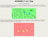 Vasantha VU2VWN VFO controlled 40m Tansmitter schematics
 -
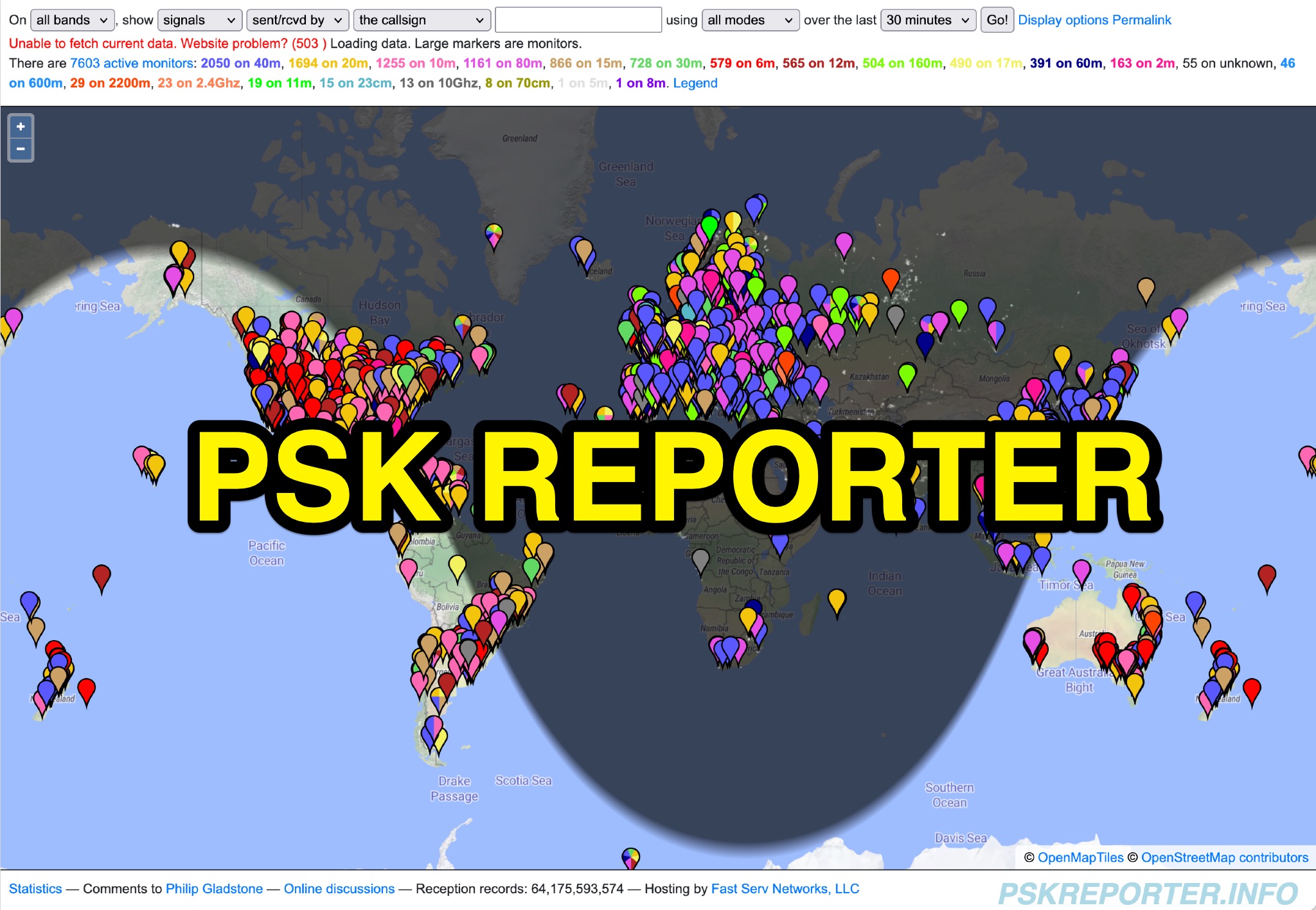 PSK Reporter provides a real-time visualization of amateur radio digital mode reception reports, aggregating data from a global network of monitoring stations. This platform is particularly useful for operators utilizing modes such as FT8, FT4, and PSK, allowing them to observe signal propagation paths and assess their station's reach. The interactive maps display reception reports, enabling hams to analyze band conditions and optimize antenna performance for various frequencies and times of day, aiding in understanding ionospheric conditions. Operators can filter reports by callsign, band, mode, and time, gaining insights into specific propagation events or evaluating the effectiveness of their transmit setup. The data collected helps in predicting optimal operating windows for DX contacts across various digital modes. Philip Gladstone is the contact person for comments and discussions regarding the system.
 -
 Transferring Radio Frequency Energy from Your Transmitter to Your Antenna by Don Keith N4KC
 -
 ATV products manufacturer, antennas, ATV transmitters, SWR meters, amplifiers
 -
 The Kenwood TS-870S HF transceiver features two state-of-the-art 24-bit 20 MIPS DSP chips, providing over 100dB out-of-passband attenuation and CW bandwidth adjustable to 50 Hz. It operates across 160-10 meters with 100 watts output, incorporating digital filtering, a beat canceller, and 100 memory channels. The radio also includes a transmit equalizer, RX antenna input, and a K1 Logic Keyer, enhancing signal processing and operational flexibility for amateur radio operators. Advanced capabilities include IF stage DSP, dual noise reduction, and an auto notch filter, all contributing to superior signal reception and clarity. The TS-870S offers a variable AGC, voice equalizer, and an RS-232C port for computer control, with Windows™ software supplied. Its built-in automatic antenna tuner functions on all bands for both transmit and receive modes, streamlining station setup and operation. Available accessories such as the DRU-3A digital recording unit, SO-2 high stability crystal oscillator, and VS-2 voice synthesizer option further extend the transceiver's utility. The unit requires 13.8 VDC at 20.5 Amps and is supplied with an MC-43S hand microphone, making it a comprehensive station component.
 -
 How to improve your transmitting antennas for very low solar activity periods, vertically polarized 160 meter antennas, horizontally polarized 80 to 10 meter antennas, single or stacked yagis, multi-tower stations
 -
 A cavity filter, often a critical component in _duplexer_ designs, functions as a sharply tuned resonant circuit, allowing only specific frequencies to pass while attenuating others. These filters are essential for maintaining signal integrity in environments where multiple transmitters and receivers operate simultaneously on closely spaced frequencies, such as in repeater stations. The article details how these filters, sometimes referred to as _notch filters_, achieve high Q factors, which are crucial for their performance. Understanding the principles of cavity filters is fundamental for any amateur radio operator involved in repeater operation or designing custom RF front-ends. The discussion covers the basic circuitry and operational characteristics that enable these devices to provide significant isolation, often achieving **-80 dB** or more between transmit and receive paths. This level of isolation is vital for preventing receiver desensitization and intermodulation distortion. Properly tuned cavity filters ensure that a repeater can transmit and receive simultaneously on different frequencies without self-interference, a common challenge in VHF/UHF operations.
 -
 The 2200-meter band (135.7-137.8 kHz) presents unique challenges for amateur radio operators due to its narrow 2.1 kHz bandwidth, low signal levels, and high noise. W1TAG explores various transmission modes suited for this demanding environment, highlighting that traditional voice modes like SSB and AM are impractical. Plain old CW serves as the baseline, demonstrating effectiveness across different modes, though signal-to-noise ratio (SNR) significantly limits practical speeds. The article notes that reducing CW speed below 5 WPM can improve copy, especially with computer-aided spectrum analysis software capable of decoding signals too weak for human ear reception. QRSS, or "CW sent slowly enough that speeds are best expressed in seconds per dot," is a key mode for LF work, with examples ranging from 3 seconds/dot to extreme 240 seconds/dot transmissions. _Argo_ by I2PHD is mentioned as a simple program for QRSS, enabling reception of signals like BRO, a Part 15 beacon, at a distance of **1100 miles**. Other modes discussed include Dual Frequency CW (DFCW), which uses frequency shifts to distinguish dots and dashes, and Binary Phase Shift Keying (BPSK), a phase modulation technique employing 0 to 180-degree phase flips. WOLF (Weak-signal Operation on Low Frequency), a specialized BPSK form by KK7KA, encodes 15-character messages into 960-bit packages, taking 96 seconds to transmit, and has demonstrated successful reception over **672 seconds** for a message from a 1-watt beacon. Further modes include PSK, FSK variations like JASON and MSK, and graphical modes such as Hellschreiber and Chirped Hell. The article concludes with a practical chart comparing the time required to send a simple message like "WD2XES FN42CH " across these diverse LF modes, offering valuable insights for operators planning contacts on the low bands.
 -
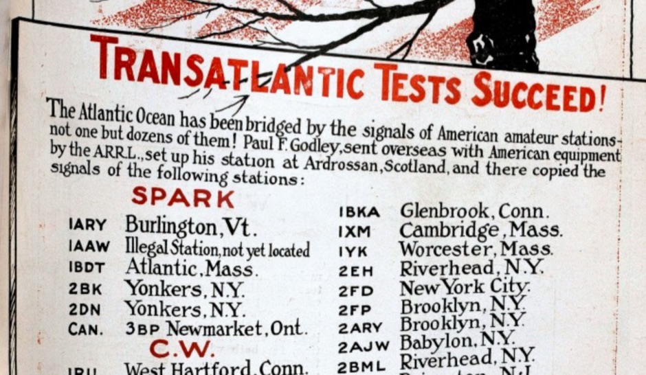 From 1921 to 1924, radio amateurs experimented with transmitting across the Atlantic. Everyday Engineering magazine organized the first sending test with English amateurs prepared to listen for signals from the US
 -
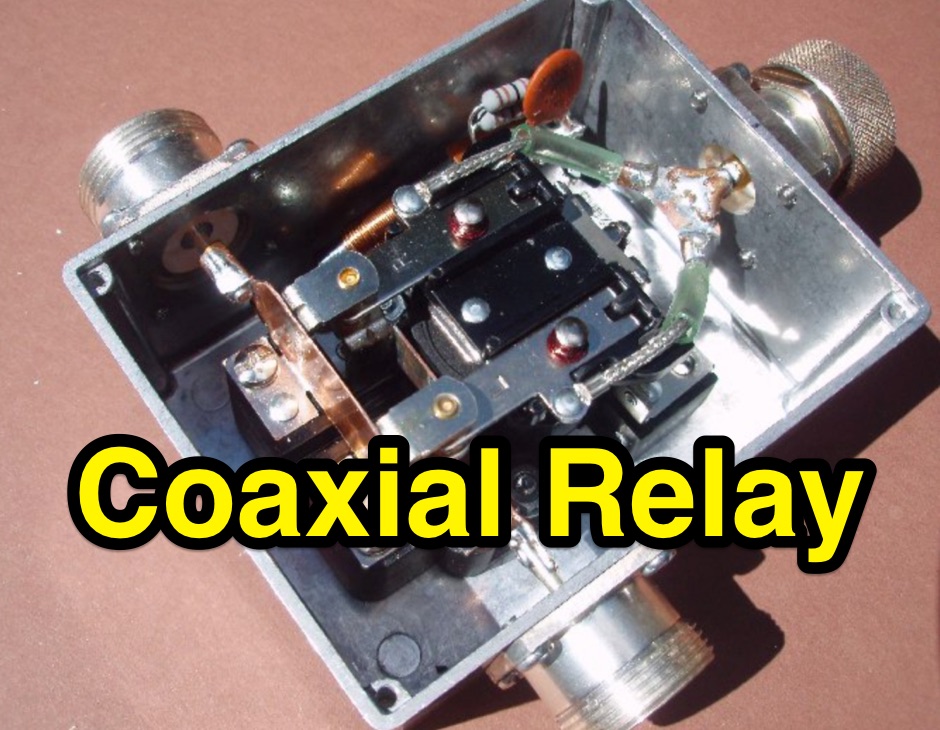 Build a SPDT coaxial relay that can be used as a main Transmit/Receive relay or an A-B switch to select between two different 6m antennas
 -
 Amateur Television (ATV) operations involve transmitting and receiving live or recorded video and audio signals over amateur radio frequencies. Unlike narrow-band modes, ATV utilizes a wider bandwidth to convey video information, often requiring specialized transceivers, antennas, and signal processing equipment. This mode allows hams to share visual content, demonstrate projects, or conduct video conferences, typically on VHF, UHF, and microwave bands due to the bandwidth requirements. The SwissATV resource focuses on the technical aspects and community engagement surrounding ATV within Switzerland. It covers topics relevant to setting up ATV stations, understanding signal propagation at higher frequencies, and participating in local ATV activities. The site serves as a central point for Swiss ATV operators to exchange knowledge and coordinate transmissions, fostering the growth of this specialized amateur radio mode.
 -
 Sixty-meter repeaters typically use a 1 MHz frequency separation between input and output, while 2-meter repeaters commonly employ a **600 kHz** split and 70-centimeter repeaters use a **5 MHz** offset. This article details the fundamental technical principles of amateur voice repeaters, explaining how they extend VHF/UHF communication range by receiving on one frequency and simultaneously retransmitting on another. It covers essential components such as receivers, transmitters, filters, and antennas, often situated on elevated locations for optimal coverage. The resource delves into the critical challenge of _desensing_—where the repeater's strong transmit signal overpowers its own receiver—and the engineering solutions employed, including antenna separation and the use of high-Q cavity filters. It also explores various control and timing systems, from basic squelch activation to more sophisticated microcontroller-based boards that manage functions like voice identification, time-out timers, and fault protection. Different access methods are discussed, including open access, toneburst, CTCSS subtone, and DTMF, each offering distinct advantages for managing repeater usage and mitigating interference. Furthermore, the article examines repeater linking, both conventional RF methods and modern internet-based solutions, highlighting how linking expands coverage and promotes activity across multiple repeaters or bands. It introduces less common repeater types such as 'parrot' repeaters, which use a single frequency and digital voice recording, and linear translators, capable of relaying multiple signals and modes simultaneously across different bands, often found in amateur satellites.
 -
 Designing and constructing a two-element receiving loop antenna array for HF operation involves specific considerations for achieving high directivity and noise reduction. This resource details a homebrew system comprising two 30-inch diamond-shaped loops, spaced 20 feet apart, which are fed through mast-mounted preamplifiers and passive signal combiners. The operational principle relies on adjusting phase delays between elements via precise _Belden 8241_ coaxial cable lengths, optimized for specific bands from 160m to 20m. Performance data, derived from _EZ-NEC_ modeling, illustrates consistent 90° azimuth-plane beamwidth and low take-off angles across the target bands, with _Receiving Directivity Factor_ (RDF) values comparable to a 300-foot Beverage antenna. The article presents detailed elevation and azimuth plots for 20m, 30m, 40m, 80m, and 160m, demonstrating the array's ability to provide strong response at low DX angles while also supporting _NVIS_ signals. Key components like the _DX Engineering RPA-1_ preamplifier and _DXE RSC-2_ signal combiner are discussed, alongside the importance of impedance matching to preserve antenna patterns. The construction emphasizes self-contained elements that do not require ground radials, offering a compact solution suitable for suburban environments and stealth installations, with a focus on optimizing receive performance independently from transmit antennas.
 -
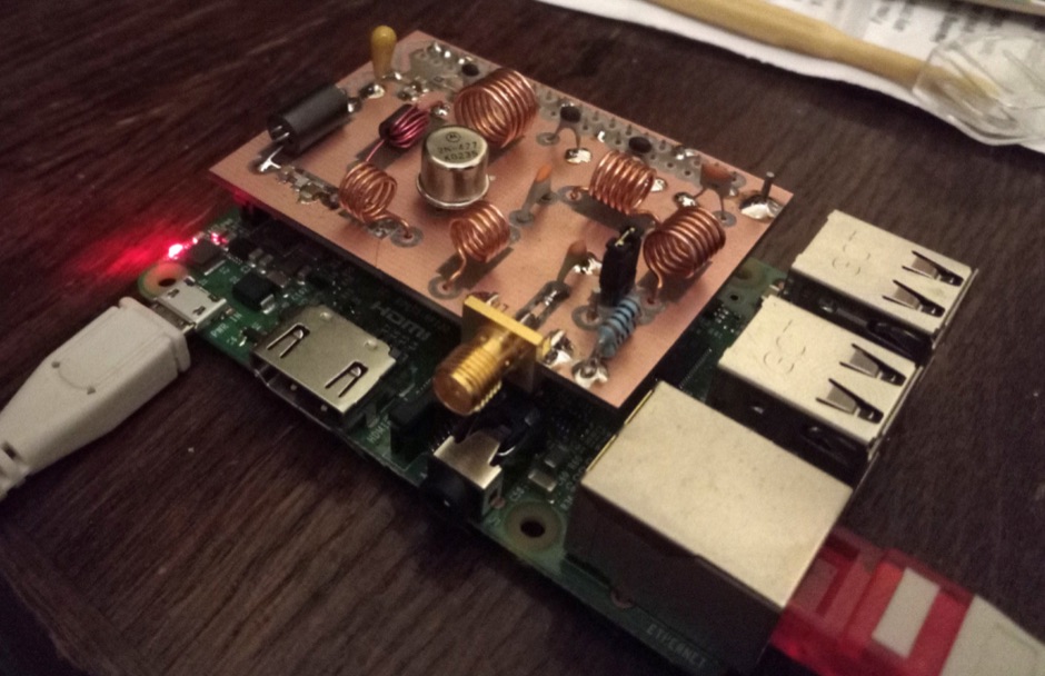 How to limit unwanted harmonics from your raspberry Pi radio transmitter by introducing filters.
 -
 An home made antenna switch with a Dummy Load selector. If you forget the radio is connected to the open or grounded side of the switch and you try to transmit, it is very easy to damage the finals of your transceiver.
 -
 Developing operational amateur radio equipment for the 134 GHz band presents significant technical challenges, particularly in frequency generation and stability. This resource details the construction of a 134 GHz system, outlining its architecture with separate transmit (Tx) and receive (Rx) modules, each employing a local oscillator (LO) and RF head units. The system utilizes a dual Flann 50 GHz lens-type horn antenna configuration for optimal signal coupling. The transmit path incorporates an LMX2541 synthesizer chip operating at approximately 2.8 GHz, referenced by a 10 MHz double-oven Morion OCXO for exceptional stability. This signal is multiplied through a series of stages (X4, then X2) to generate a 22.4 GHz signal, which subsequently drives a dual series diode multiplier to produce the final X6 signal for 134 GHz operation. The receive side features an anti-parallel diode mixer coupled to a 144 MHz transceiver via a preamplifier, ensuring effective downconversion. Operational mode is CW, achieved by keying a multiplier stage. The project includes images of the Tx and Rx head units and describes a successful 3.5 km test with G8ACE, demonstrating stable signal tones due to PLLs locked to OCXOs at both ends, confirming the system's robust performance.
 -
 The PI6ATV repeater, operating on 10.475 MHz, serves the amateur television community by providing both analog and digital DVB-S2 services. Recent updates include user-adjustable Symbol Rate settings via Webcontrol, allowing operators to optimize their digital ATV transmissions for various conditions. This functionality, implemented on December 13, 2022, enables dynamic configuration of the digital stream. Significant technical milestones include the return of the analog ATV transmitter on 10.475 MHz, featuring a newly constructed liquid-cooled final amplifier by Edwin PD2EBH. This restoration on September 6, 2020, followed an 18-month hiatus, ensuring continued support for traditional analog ATV enthusiasts. The repeater's transition to DVB-S2 modulation, initiated on December 20, 2018, addressed capacity limitations of the previous DVB-S setup. This change from 20 MS/s with FEC 3/4 to DVB-S2 allowed for more efficient data handling, accommodating multiple channels within the available bandwidth and enhancing the overall digital ATV experience.
 -
 The video delves into the fascinating science behind antennas, which are crucial for receiving and transmitting electromagnetic waves. It explains how antennas convert electric signals into electromagnetic waves for transmission, and how they operate through the oscillation of positive and negative charges in dipole arrangements. Practical antenna implementations, such as dipole antennas for TV reception and Yagi-Uda antennas with reflectors and directors, are also discussed alongside modern dish TV antennas with parabolic reflectors for signal processing. It's a comprehensive overview of how antennas work and their significance in communication technology.
 -
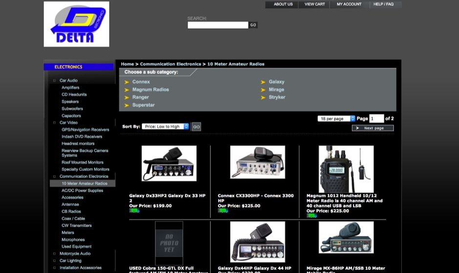 Delta Electronics, Inc. NY USA, family owned and operated selling all varieties of consumer electronics including 10 meter amateur radios, antennas, accessories, microphones, cw transmitters, coax cables and more
 -
 Documents the operational experiences and technical insights of amateur radio station VA3STL, offering a firsthand account of various on-air activities and equipment. The blog features a detailed narrative of a **QRP transatlantic QSO** on 12m SSB, achieving a 55 report with 10W to a mobile station in Italy using a homebrew 90ft doublet antenna. It also introduces the _Ten-Tec 539_ QRP HF transceiver, a 10W output rig covering 80m through 10m, designed for portable operations and featuring DSP and dual VFOs. The resource also delves into historical radio technology, specifically the "Gibson Girl" survival radio, an emergency transmitter operating on 500kHz (and later 8280/8364 kHz) with a hand-cranked generator and kite-deployed antenna. This section explores its origins from German designs and its use during World War II, including its distinctive curved shape for ergonomic hand-cranking. Further historical content includes a visit to Signal Hill in St. John's, Newfoundland, commemorating Marconi's reception of the first transatlantic radio signal in 1901. The post describes the Cabot Tower exhibit and the VO1AA station, highlighting the site's significance despite the thick fog during the visit. It also showcases a homebrewed _Marconi-style straight key_ by WB9LPU, crafted to celebrate the centenary of Marconi's achievement.
 -
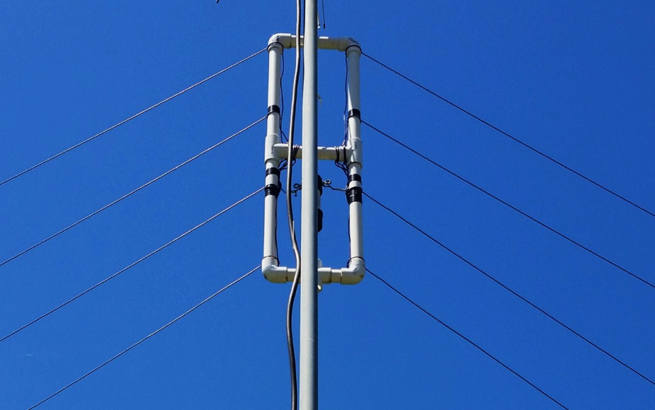
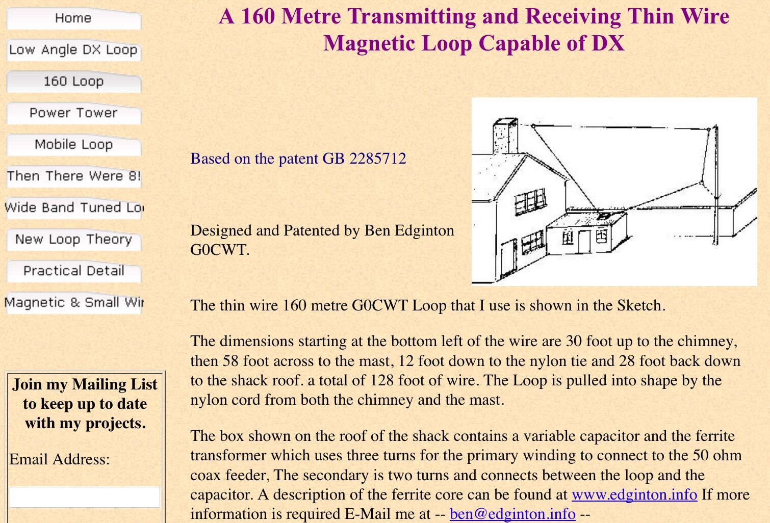 A 160 Metre Transmitting and Receiving Thin Wire Magnetic Loop Capable of DX. Designed and Patented by Ben Edginton G0CWT
 -
 Available worldwide can be used as Arduino Shield or plug it in to you PC , or with a bluetooth adapter connect to Android. With a highly optimized software, KAI200 brings you: a. Antenna analyzer form 1 up to 200 Mhz; b. WSPR transmiter (set up by serial terminal); c. Square Wave Signal generator KAI200 is all you need for your radio whatever it is Yaesu, Icom, Kenwood or Drake and DIY projects.
 -
 The ZS1J/B beacon operates on 28.2025 MHz with 5 Watts output to a half-wave, end-fed vertical antenna, initially installed in 1977 as ZS5VHF near Durban. The 10-meter transmitter is a modified 23-channel CB radio, and the identification keyer uses a diode matrix unit with TTL ICs from the same era. After relocation to Plettenberg Bay in 1993, the beacon has been in continuous service, with additional QRP transmitters later installed for other bands. In 1994, a single-transistor, 80-meter, 0.5-watt QRP transmitter with a half-wave dipole was added on 3586 kHz, followed by a 160-meter, 0.5-watt unit on 1817 kHz. A 30-meter, 0.5-watt transmitter was installed in 1996, operating on 10.124 MHz. In 2002, a 40-meter QRRP beacon on 7029 kHz, with an output of 100 microwatts, achieved DX reports up to 1100 km from ZS6UT in Pretoria. Best DX reports for the 80m and 160m beacons came from 9J2BO.
 -
 Low-frequency (LF) radio time signals, operating primarily in the 40–80 kHz range, are broadcast by national physics laboratories for precise clock synchronization. Transmitters like **JJY** (40 kHz, 50 kW; 60 kHz, 50 kW), RTZ (50 kHz, 10 kW ERP), MSF (60 kHz, 15 kW ERP), WWVB (60 kHz, 50 kW ERP), RBU (66.66 kHz, 10 kW), and DCF77 (77.5 kHz, 50 kW) cover vast geographic areas, often several hundred to thousands of kilometers. LF signals offer distinct propagation advantages over higher-band transmissions such as GPS. Their long wavelengths (3–6 km) enable effective diffraction around obstacles like mountains and buildings. The ionosphere and ground act as a waveguide, eliminating the need for line-of-sight and allowing a single powerful station to cover extensive regions. Ground wave propagation minimizes ionospheric variability effects on transmission delay, and signals penetrate most building walls effectively. Robust and low-cost receivers, often priced at 20–30 USD/EUR, are widely used in radio clocks. These receivers typically comprise a tuned ferrite core antenna, a receiver IC (e.g., Atmel T4227, U4223B, MAS1016) for amplification and AM detection, and a microcontroller for decoding the time signal and phase-locking a local clock. Specific components for DCF77, MSF, and WWVB are readily available from vendors like HKW Elektronik and Ultralink.
 -
 On December 12, 1901, Guglielmo Marconi successfully received the first transatlantic wireless communication, a Morse code "S" (three dots), at 04:30 GMT. This article details the setup for this groundbreaking experiment, noting Marconi's receiver in St. John’s, Newfoundland, Canada, utilized a _coherer_ and an antenna elevated by balloons and kites. The transmitting station at Poldhu, Cornwall, England, featured twenty-four 200-foot ships' masts and a 25-kilowatt alternator. The resource explains how this contact disproved contemporary beliefs about radio wave limitations due to Earth's curvature, later understood through _ionospheric propagation_. It frames Marconi's achievement as the "very first DX" in amateur radio terms, defining DX as telegraphic shorthand for distance and _DXing_ as the hobby of receiving distant signals. The article also provides external links for further reading on Marconi's experiments and the science behind transatlantic radio signal reception.
 -
 Thsi article describes a microcontroller driven semi-automatic antenna tuner capable of handling power levels up to 150 watts. The device is a low pass filter tuner manually tuned by setting the optimized L/C combination by hand and then storing the values into the EEPROM of the mictrocontroller to recall them later (seperately for each band from 80 to 10 meters including WARC bands)
 -
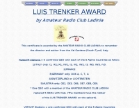 The **Luis Trenker Award** is an amateur radio operating award established by the Amateur Radio Club Ladinia to honor the director and author Luis Trenker from Val Gardena, South Tyrol, Italy. To qualify for the award, HF stations must achieve five confirmed QSOs with each of five specific Alpine countries: Italy (with specific prefixes like I1, IK1, I2, I3, IN3, IW3, IV3), France, Germany (with DOKs A, C, T, U), Switzerland or Liechtenstein, and Austria (with prefixes OE2, OE3, OE6, OE7, OE8, OE9). A single QSO with a member of the Amateur Radio Club Ladinia can substitute for the five required Italian QSOs, with members' QSL cards bearing a special rubber stamp. VHF/UHF stations have a simpler requirement, needing only one confirmed QSO with each of the five Alpine countries. SWL stations are eligible under the same conditions as transmitting stations. All contacts must be valid after April 12, 1990. Applicants must submit a list of contacts, certified by two OMs or a club, to the Amateur Radio Club Ladinia in Ortisei, South Tyrol, Italy. The award manager is IN3PGS Karlheinz, and the club official is IW3AQL Luca.
 -
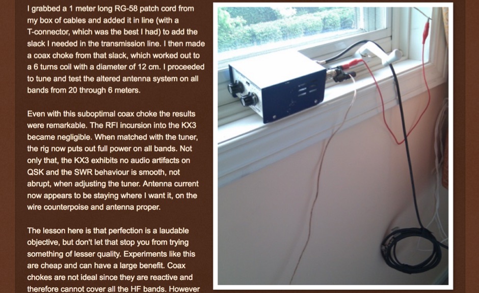
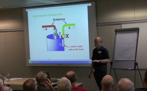 Our ideas about HF baluns have changed dramatically in recent years. The focus today is very much on suppressing unwanted common-mode RF currents, to reduce both the received noise levels and the risks of causing interference on transmit.