Search results
Query: tri band antenna
Links: 186 | Categories: 2
-
 Operational testing of a 10.07-meter portable HF vertical antenna, constructed from telescoping aluminum tubing (36, 32, 22, 17 mm diameters), yielded SWR measurements below 1.5 across multiple bands. Initial trials on 14.150 MHz showed an SWR of 1.6, while 7.075 MHz was problematic. Subsequent adjustments, including a 13 cm extension to the radiating element, improved performance, enabling operation on 6, 15, and 40 meters without a balun, and adding 12 meters with a balun. The design prioritizes portability, allowing transport in a standard vehicle and single-person deployment. Four 10.07-meter radials are connected at the base to enhance ground plane effectiveness. The article details the mechanical assembly, including custom adapters for tube transitions and a PVC sanitary tube sleeve for base insulation, ensuring robust field deployment. Final SWR measurements, documented with an _MFJ-259_ antenna analyzer, confirm operational ranges: 6.800-7.500 MHz (SWR < 1.5), 20.800-22.500 MHz (SWR < 1.5), and 48.800-51.500 MHz (SWR < 1.5) without a balun. With a balun, the antenna achieved SWR < 1.5 on 13.750-15.000 MHz and 24.890-28.350 MHz, demonstrating its versatility for portable _DXpeditions_.
 -
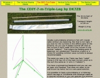
 This antenna consists of 4 resonate dipoles made from 12 insulated copper electrical wire. The dipoles are resonate on the following bands: 6 meters, 10 meters, 12 meters and 17 meters.
 -
 This resource details the conversion of an 80m elevated vertical antenna to include 160m operation, focusing on a relay-switched design over a trap-based approach. It presents specific feedpoint impedance values, such as **32 ohms** for 80m and **14 ohms** for 160m, and discusses the challenges of SWR drift encountered with the prior trap system during RTTY contesting. The article thoroughly explains the design choices for elevated radials, referencing _N6LF QEX data_ to debunk common myths regarding radial length and height, demonstrating that non-resonant radials can offer superior current uniformity. The construction section provides practical insights into building the vertical, including guying strategies, material selection from scrap pipe, and weatherproofing the relay assembly. It highlights the use of a common mode choke for the relay switching line, measuring approximately 5K ohms on both 160m and 80m, and details the L/C matching network's role in achieving a 50-ohm match at the end of a 300-foot RG-11 run. The author describes a precise VNA-based radial trimming procedure, achieving resonant values within a 3 KHz range. The content emphasizes the practical application of theoretical antenna principles, particularly concerning the interaction between the vertical element, cap hats, and the matching network. It offers a candid assessment of component selection, such as using junkbox parts and acknowledging the need for future upgrades to static drain resistors. The article serves as a comprehensive case study for advanced antenna builders tackling multi-band vertical designs.
 -
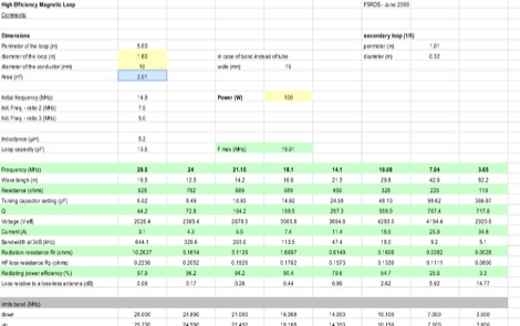 Excel spreadsheet that help calculating dimensions of a high efficiency magnetic loop antenna for HF bands. Giving in input the loop perimeter, loop diameter and loop conductor will calculate electric characteristics, bandwidth, and efficiency
 -
 This project produces an inexpensive, multiband, end fed HF antenna matchbox, quick and easy to setup. This project creates a trifilar wound, 9:1 UNUN toroid matching transformer. Handles 100W and need an antenna tuner.
 -
 For radio amateurs seeking compact and efficient antenna solutions, particularly for restricted spaces or noise reduction, HF loop antennas present a viable option. This resource compiles several articles from the ARRL, detailing the theory, design considerations, and practical construction of various loop configurations. Topics include small transmitting loops, receiving loops, and multi-band designs, often emphasizing their performance characteristics such as directivity, bandwidth, and impedance matching. The collected articles provide insights into the comparative performance of different loop geometries, such as circular versus square loops, and discuss the impact of conductor size and tuning methods on efficiency. Practical applications are explored, including their use in portable operations, stealth installations, and urban environments where noise mitigation is critical. The content often includes construction diagrams, parts lists, and performance data derived from modeling or field tests, enabling hams to replicate or adapt the designs for their specific operating conditions.
 -
 This strange looking antenna is a combination of Coupled-Resonator principle by K9AY and a quarter stubs to achieve low angle radiation pattern. Designed with 4nec2 NEC based antenna modeler and optimizer for 145/220/440MHz bands
 -
 The ZS6BKW antenna, a popular multiband wire antenna, offers improved band matching compared to the traditional G5RV. This construction guide details the process, beginning with specific dimensions: 13.11 meters (43 feet) for the 450-ohm ladder line and initial dipole arm lengths of approximately 14.8 meters each. It emphasizes the critical role of an _antenna analyzer_ for accurate tuning, particularly for determining the velocity factor of the ladder line and achieving a 1:1 impedance match. The article outlines the materials required, including a 1:1 current balun, 450-ohm window line, wire for the dipole arms, and a 50-ohm non-inductive resistor for testing. It provides a step-by-step procedure for cutting the ladder line to its electrical half-wavelength, explaining how to calculate the velocity factor using measured and free-space frequencies. For instance, a measured 50-ohm impedance at 12.54 MHz with a calculated free-space half-wavelength frequency of 11.44 MHz yields a velocity factor of 0.91. Final adjustments involve hoisting the antenna to its operational height and fine-tuning the dipole arm lengths to achieve optimal SWR, specifically targeting 14.200 MHz. The _ZS6BKW_ design is noted for its performance on 80m, 40m, 20m, 10m, and 6m, though it is not optimized for 15m operation. The author, _VK4MDX_, shares practical tips for durable construction using stainless steel wire and cable clamps.
 -
 Demonstrates the design and construction of a compact, portable multi-band mini-delta loop antenna, specifically optimized for /P (portable) operations from remote locations like Scottish islands. The resource covers the theoretical underpinnings of half-wave loops, contrasting closed and open configurations, and then details the application of a folded dipole principle to achieve a 50-ohm match for direct coax feed. It presents empirical formulas for calculating element lengths, considering the velocity factor of common wire types, and provides a detailed example for a 20m (14.175 MHz) version. The article includes a comprehensive table of dimensions and allowances for a five-band (20m, 17m, 15m, 12m, 10m) mini-delta beam, along with construction hints for the central support and balun. It specifies a 1:1 trifilar balun wound on a ferrite rod and describes the antenna adjustment process using an _MFJ-259B Antenna Analyser_. Initial test results indicate an SWR of 1:1 at resonance and a bandwidth of approximately 240 kHz on 20m, even at a low height of five feet above ground. The distinctive utility lies in its focus on a practical, easily deployable beam antenna for portable DXing, offering a viable alternative to more complex or larger arrays.
 -
 GW4ALG's _136 kHz Pages_ document the evolution of vertical antennas for the 2200m band, starting with a prototype mounted on a house wall. This initial design, despite achieving the first **395 km** GM-GW QSO, suffered from significant insulation breakdown, high RF losses due to proximity to the house, and difficult tuning adjustments. The author details the challenges of maintaining resonance and matching with a variometer in the loft, noting that adding three earth spikes offered no measurable improvement over a simple water tap connection. The subsequent experimental 12m vertical, relocated away from the house, significantly reduced dielectric losses and proved far more effective. This antenna enabled GW4ALG to set a world DX record on 136 kHz with a **1916 km** QSO to OH1TN, and an intra-UK record of **703 km** to GM3YXM/P. The resource further explores the use of helium-filled balloons to extend the vertical radiator, achieving heights up to 27m, typically 20m, for enhanced low-band performance. Practical advice on balloon types, inflation, and critical insulation between the wire and balloon is provided, emphasizing safety and avoiding arcing.
 -
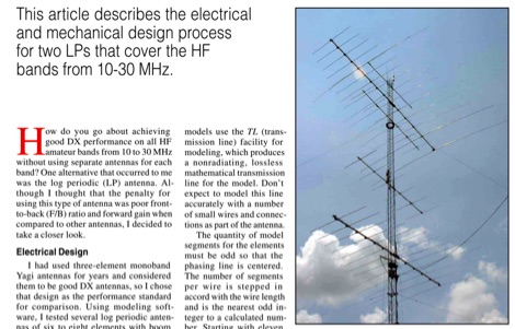
 A triband VHF Yagi antenna for 6 m, 4 m and 2 m with one feed-point by DK7ZB
 -

-
 Over 1,000 stations in approximately 60 countries were worked using this modified twin-lead folded dipole, demonstrating its effectiveness with just 4 watts on 20 meters. This design, adapted from an ARRL Handbook concept, eliminates the shorting strap found in traditional folded dipoles, simplifying construction while maintaining performance. It utilizes readily available 300-ohm TV antenna feeder ribbon, making it a cost-effective solution for radio amateurs. The antenna's robust construction allows it to handle up to 100 watts without issues, even without a **balun**. The inclusion of a variable trimmer capacitor at the stub provides flexibility for tuning across different frequencies within a band, a practical feature for operators using transceivers like the Icom 735. Formulas are provided to calculate the precise dimensions for any desired operating frequency, enabling customization for various **HF bands**.
 -
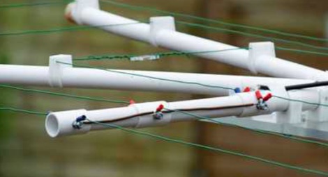 A PDF presentation of a home made moxon antenna for 50 MHz 70 MHz and 144 Mhz. The project is mainly out of surplus plastic Plumbing pipes and clips etc, and also details of how the dimensions were calculated.
 -
 The G5RV multiband HF antenna, designed by Louis Varney (G5RV) in 1946, is a popular compromise antenna offering good overall performance on most HF bands when paired with an external antenna tuner. The basic full-size G5RV measures 102 feet across the top for 80 through 10 meter operation and is fed at the center via a 34-foot low-loss feed-stub. This interaction between the radiating section and the feed-stub facilitates matching across 80-10 meters with a standard tuner, often eliminating the need for ladder line directly to the shack. The antenna's design center frequency is 14.150 MHz, configured as a 3/2-wave dipole on 20 meters, with its 102-foot length derived from long-wire antenna formulas. Construction details emphasize the matching section, which can be open wire, ladder line (window-type), or TV twin lead. Each type has a specific velocity factor (VF) affecting its physical length for an electrical half-wave on 14 MHz; for instance, open wire requires 33.7 feet (VF 0.97), ladder line 31.3 feet (VF 0.90), and TV twin lead 28.5 feet (VF 0.82). The article provides formulas for calculating these lengths and discusses the antenna's behavior on individual bands, from 3.5 MHz where it acts as a shortened dipole, to 28 MHz where it functions as two three-half-wave long-wire antennas fed in-phase. Practical construction notes include recommendations for vertical descent of the matching section, sealing the coax junction, providing strain relief, and winding a coaxial choke coil to mitigate common mode current. The resource also presents dimensions for double-size (204 ft) and half-size (51 ft) G5RV versions, along with their corresponding matching section lengths for various line types, making it a versatile reference for hams considering this classic wire antenna.
 -
 3 band mobile antenna - 10m full size wave/4 whip - quick tilt-down system for 20 and 15 m loading coil change by IZ7DJR
 -
 A 5 band two element quad antenna working from 20 to 10 meters using hardware-store parts or modifying an existing commercial triband quad by KC6T
 -
 An inverted triangle Delta Loop Antenna for the 40 meter band made with aluminium pipes, each element is 14,2 meters including a home made aluminium mount.
 -
 Industrial Communication Engineers (ICE) was a manufacturer specializing in **RF components** and solutions for amateur radio and commercial applications. Their product line included a range of RF parts, various types of filters, and RF switching products designed to enhance station performance and mitigate interference. These components were critical for hams engaged in contesting, DXing, or general operating, providing means to improve signal integrity and manage complex antenna systems. The company's offerings addressed common operational challenges such as RFI and TVI, with products like **low pass filters** and antenna filters. While the specific technical specifications of their product range are no longer available, such components typically provided significant attenuation of unwanted harmonics and out-of-band emissions, crucial for maintaining a clean signal and preventing interference with other electronic devices. The current status indicates the domain is for sale, suggesting the manufacturing operations have ceased.
 -
 One point eight MHz to 30 MHz is the operational bandwidth for this 4:1 Ruthroff voltage balun, designed to interface an unbalanced T-Match network with a balanced antenna system. The project details the construction using a _T200-2_ powdered iron toroid core, tightly wrapped in PVC electrical tape for insulation, and wound with 17 double bifilar turns of 1.25mm enamelled copper wire. This outboard balun offers flexibility, allowing hams to trial various baluns based on antenna system and impedance characteristics, rather than integrating it directly into the tuner. The resource includes a schematic of the balun, a wiring diagram showing winding connections, and a table suggesting alternative toroid cores like the T80-2 or T400-2 with corresponding winding counts. Component sourcing is straightforward, listing items such as the _Amidon_ T-200-2 core, SO-239 connector, and a sealed polycarbonate enclosure from Jaycar. Performance evaluation was conducted using an _AIM 4170C_ antenna analyser, demonstrating efficient 1:4 voltage transformation across the specified HF spectrum. Further efficiency tests involved measuring RF power loss at various frequencies, revealing minimal loss—less than 0.7 dB from 3.6 MHz to 30 MHz, and only 2.0 dB at 1.8 MHz. These measurements, performed under ideal 50-ohm conditions, confirm the balun's effectiveness as a low-loss interface for multi-band antenna systems. The page also links to several other balun and unun projects, including 1:1 current and voltage baluns, and 9:1 voltage ununs, providing a broader context for impedance matching solutions.
 -
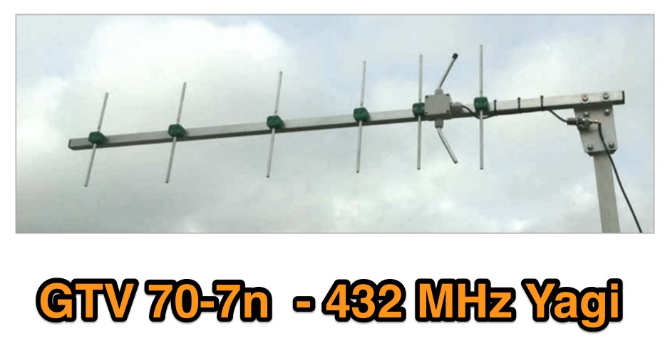
 Presents a curated collection of newsletters dedicated to _Earth-Moon-Earth_ (EME) communications, primarily focusing on the 432 MHz band and higher microwave frequencies. The resource details various EME DX experiences and news contributions from operators like K2UYH (W6/PA0ZN), offering insights into successful moonbounce contacts and operational strategies. It serves as an archive of specialized content for those engaged in or interested in extreme weak-signal propagation via the moon. The newsletters provide practical information on achieving EME contacts, often including details on station setups, antenna arrays, and signal reports from challenging DX. For instance, operators might report achieving contacts over **750,000 km** round trip, demonstrating the feasibility of long-distance communication on UHF and microwave bands. The content differentiates itself by concentrating on the unique technical and operational aspects of EME, which contrasts significantly with terrestrial DXing, providing a specialized knowledge base for advanced amateur radio operators.
 -
 Presents a QRP AM/CW transmitter project specifically designed for the 10-meter band, utilizing a crystal oscillator and a collector-modulated AM oscillator. The design employs a 2N2219(A) transistor in a Colpitts configuration, generating 100 to 350 mW of RF output power depending on the 9-18 Volt supply voltage and modulation depth. Frequency stability is maintained by a 28 MHz crystal, with fine-tuning possible via a Ct1 trimmer capacitor for approximately 1 kHz adjustment. The resource details the RF oscillator stage, implemented with a 2N2219 NPN transistor, emphasizing frequency stability and low power dissipation. It also covers the amplitude modulation stage, managed by a 2N2905 PNP transistor, which impresses audio information onto the carrier. Selective components (C3, C4, C7, C5) enhance voice frequencies within a +/- 5 kHz bandwidth, and modulation depth is controlled by R2 and R3. The project includes a 3-element L-type narrow bandpass filter (Ct3, L3, C10) to suppress harmonics and ensure a clean output signal. The project provides a complete schematic diagram, a comprehensive parts list including specific capacitor, resistor, and inductor values, and construction notes for the coils (L1, L2, L3). It also offers practical advice on enclosure requirements, suggesting an all-metal case or a PVC box with graphite paint for RF shielding. Operational parameters such as current draw (27mA@9V to 45mA@16V) and input impedance (50 Ohms) are specified, alongside guidance on antenna matching and the importance of a valid amateur radio license for 10-meter band operation.
 -
 The ZS6BKW multiband antenna, an optimized variant of the classic G5RV, features a 102-foot (31.1 m) horizontal span and a 39.1-foot ladder line matching section. This design, derived by G0GSF (formerly ZS6BKW) in the early 1980s using computer programs and _Smith charts_, aims for improved SWR across multiple HF bands compared to its predecessor. Construction details specify Wireman 554 ladder line and #14 AWG THHN copper wire for the radiators, with precise instructions for determining the velocity factor (VF) of the ladder line using an antenna analyzer or dip meter, ensuring accurate physical length for the matching section. The radiator length is electrically 1.35 wavelengths for the 20-meter band, requiring careful trimming during tuning. Field measurements with an _AIM-4170C_ analyzer by KI4PMI and NC4FB demonstrated good SWR curves and bandwidth on 6, 10, 12, 17, 20, and 40 meters. The antenna was deemed unusable on 15 and 30 meters due to very high SWR, but an LDG AT-100PRO autotuner successfully brought 6 and 80 meters into tune. Contacts were made on 80, 40, 20, and 17 meters, including a **17-meter** contact to Spain. EZNEC models for 80-6 meters are provided, along with an AutoEZ model by AC6LA, which predicted good SWR for 80-10 meters. W5DXP's modifications for an all-band HF ZS6BKW are also referenced.
 -
 The _Italian VHF Beacons_ resource provides a detailed listing of active and QRT amateur radio beacons operating across VHF, UHF, and SHF bands within Italy. Each entry specifies the beacon's callsign (e.g., IQ1SP/B), operating frequency (e.g., 144.411 MHz), QTH locator (e.g., JN44VC), effective radiated power (ERP) in watts, and antenna configuration (e.g., Big Wheel, 4x Dipole, Yagi). This data is crucial for radio amateurs involved in propagation studies, equipment testing, and long-distance (DX) communication on these higher frequency bands, offering fixed signal sources for monitoring. This compilation, last updated in October 2005, serves as a historical snapshot of Italian beacon activity. For instance, it lists several 144 MHz beacons with ERPs ranging from **0.1W** to **10W**, and higher frequency beacons such as I8EMG/B on 1296.880 MHz and I3EME/B on 24192.132 MHz. The inclusion of QRT (Quiet Radio Teletype) status for many entries indicates the dynamic nature of beacon operations over time. Users can utilize this information to identify potential signal sources for band openings or to calibrate their receiving equipment against known transmissions.
 -
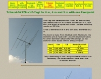 Triband DK7ZB VHF Yagi antenna for 6 m, 4 m and 2 m with a single feedpoint
 -
 Package contain 1x yaesu vx-8r 1x sma dual section antenna 1x hf antenna lithium ion battery pack fnb-101li 1x battery charger nc-86c 1x connector unit
 -
 Operating an 80/40/20M fan dipole for DX is analyzed through EZNEC modeling, focusing on the antenna's performance in a real-world, low-height installation. The resource details the physical construction and SWR measurements of the fan dipole, comparing them against EZNEC simulations. It also incorporates High Frequency Terrain Analysis (HFTA) data to illustrate typical DX elevation angles for various regions from New England, providing a crucial context for evaluating antenna patterns. The analysis presents EZNEC-generated azimuth and elevation patterns for each band (80M, 40M, 20M) at specific frequencies, showing gain figures at different elevation angles relevant to DX propagation. It compares the modeled SWR with measured SWR, attributing discrepancies to coax attenuation. The study concludes with observations on the antenna's azimuth performance (omnidirectional within ±1.5 dB) and its less optimal elevation gain at desired DX angles, highlighting the impact of low antenna height on DX capabilities.
 -
 Experiments on HF antennas for restricted spaces. In this article author experiments antennas for 80-10 meters band having just a very small garden and several restrictions. Basic antennas consists of laded multiband dipoles and fan dipole antennas
 -
 Demonstrates the adaptation and construction of a 7-element DK7ZB Yagi antenna for the 4-meter band (70 MHz), utilizing components from a defunct 2-meter CUE DEE Yagi. The resource details the modifications made to the original DK7ZB design to fit the shorter CUE DEE boom length, specifically adjusting element lengths for 6mm rod elements while reusing existing mounting holes for the reflector and last director. It provides precise element lengths for the reflector, dipole (12mm aluminum tube), and five directors, along with a note on cutting elements for transport. The article includes a 4NEC2 simulation file for performance analysis and an SWR plot, confirming the antenna's electrical characteristics. It also specifies the calculation for the quarter-wavelength matching cable using SAT752F coaxial cable, resulting in a 909mm length. Practical application is shown with the finished antenna in operation at JO20XC, listing several activated Maidenhead squares such as JO56PA and JP40KS, validating its effectiveness for portable 70 MHz operations.
 -
 The Yaesu FT-1000MP Mark-V, introduced at Dayton 2000 Hamvention, features a higher RF power of **200 W PEP** and a Class-A amplification SSB mode at 75 W. Key enhancements include an _Interlocked Digital/Analog Bandwidth Tracking system (IDBT)_, a Variable Front-End Filter (VRF) preselector, and improved ergonomics, notably a multi-function shuttle jog dial. This model, a successor to the 1996 FT-1000 and FT-1000MP, was designed to compete with high-end transceivers, despite its retail price of $4200 initially. The transceiver's physical dimensions are 406 x 135 x 348 mm (16 x 5.3 x 13.7 inches) with a weight of 14 kg (31 lbs), making it substantial. Its rear panel offers over 20 connections, including power, external DSP speaker, BAND DATA I/O, ALC, and multiple interface jacks for DVS-2, Packet, and RTTY. The unit also provides two keyer inputs, a DB9M serial interface for CAT, and two PL female antenna connectors, plus additional receive antenna jacks. Despite its advanced internal architecture, including two independent receivers with their own IF filters and AGC loops, the display technology, utilizing fluorescent discharge rather than LCD, contributes to an older aesthetic. The control panel is extensive, featuring 92 knobs and buttons, alongside numerous LED indicators for various modes and functions.
 -
 A three band short Vee antenna is feasible with two legs per side on a dipole. 10-15-20 meters by W8HDU
 -
 The X80 multi-band HF vertical antenna, a commercial iteration of the Rybakov design, exhibits a physical length of 5.5 meters, or approximately 18 feet, and is constructed from aluminum tubing. It operates as a non-resonant vertical, requiring an external antenna tuner for impedance matching across its intended operating frequencies. The antenna's design incorporates a 1:4 UNUN at its base, facilitating a nominal 50-ohm feed point impedance for the coaxial cable. Performance observations indicate effective operation on 40 meters, 20 meters, 15 meters, and 10 meters, with reduced efficiency on 80 meters and 160 meters due to its relatively short electrical length for these lower bands. Comparative analysis with a G5RV dipole and a half-wave end-fed antenna reveals the X80 offers a lower take-off angle, beneficial for DX contacts, particularly on the higher HF bands. Field tests conducted with an Icom IC-706MKIIG transceiver and an LDG AT-100ProII autotuner demonstrate the X80's ability to achieve acceptable SWR across 80m through 10m. The antenna's compact footprint and ease of deployment make it suitable for restricted spaces or portable operations, though its performance on 80 meters is noted as a compromise compared to full-size resonant antennas.
 -
 The TMB-1 is an RF amplifier unit / receiving accessory that can be used with a low-impedance broadband loop, a high-impedance terminated loop (such as a Pennant, Flag, or Kaz Delta), and whip (telescoping rod) antennas.
 -
 Examining the _Angle of Radiation_ and its impact on amateur radio operations, the resource provides insights into optimizing antenna performance for DX and local contacts. It features a design for SPOTTO, a direct conversion high-performance universal DSB transceiver, detailing its construction and operational characteristics for homebrew enthusiasts. Additionally, the site presents a 7-element VHF high-gain antenna design, offering practical schematics and expected performance metrics for those seeking enhanced gain on VHF bands. The resource also covers the development and popularity of the _FT8_ digital mode, highlighting its effectiveness in weak-signal conditions and its role in special event operations like the FT8DMC anniversary. It includes information on Hamfest India 2023 and the Lamakaan Amateur Radio Convention, providing dates and organizational details for significant Indian amateur radio gatherings. Technical articles on Direct Digital Synthesizers (DDS) VFOs and low-cost multifunctional frequency counters offer practical project ideas for radio amateurs.
 -
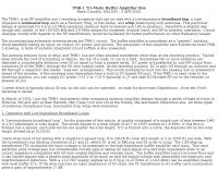
 This QST article describes the electrical and mechanical design process for two LPs that cover the HF bands from 10-30 MHz
 -
 Mitigating RF noise in a mobile operating environment, particularly within a _Jeep TJ_ vehicle, presents unique challenges due to the vehicle's electrical system and chassis characteristics. This resource details practical methods for identifying and suppressing various forms of radio frequency interference (RFI) that can degrade receiver performance for both CB and amateur radio transceivers. It covers common noise sources such as ignition systems, alternators, fuel pumps, and computer modules, explaining how these components generate broadband or specific frequency noise that impacts radio communications. The guide offers actionable solutions, including proper grounding techniques, the strategic use of ferrite beads and toroids on power and data lines, and the installation of bypass capacitors. It discusses the effectiveness of different filtering strategies for DC power lines and antenna feedlines, illustrating how a clean power supply and shielded cabling can significantly reduce conducted and radiated noise. The information presented helps operators achieve a lower noise floor, improving signal-to-noise ratio and enabling clearer reception of weak signals, which is crucial for effective mobile DXing or local ragchewing.
 -
 Based on a simple project based on a 2 elements Yagi for 20m band, and then becomed a triband yagi with a open-sleeve feed system
 -
 The supporting structure is a 15-m-glassfibre mast of DX-Wire. The antenna can be used on all bands from 10 to 40 m.
 -
 The NB6Zep Antenna, an electrically shortened 80-meter end-fed wire, addresses space constraints for low-band operation by integrating two loading coils into a 37-foot wire. This design, modeled with _EZNEC_, explores configurations like the quarter-wave sloper and inverted-L, with the latter providing a more vertical radiation pattern and practical backyard deployment. The resource details specific coil construction, recommending 21 uH coils made from _BW coil stock #3026_ or similar, and outlines wire segment lengths for optimal tuning. Performance analysis indicates a radiating efficiency of approximately 27% with good ground conductivity, resulting in a signal typically 3-4 dB down compared to a full-size quarter-wave vertical. The antenna exhibits a narrow bandwidth, around 50 kHz, due to its high Q, necessitating a tuner for broader band operation. Feedpoint impedance is low, with ground resistance playing a critical role in achieving a usable SWR. The article emphasizes the importance of an effective ground rod at the feedpoint for proper operation and tuning, suggesting an antenna analyzer for precise adjustments. It confirms the antenna's suitability for DX, citing successful contacts from Oregon to the East Coast and Hawaii on a 160-meter variant, making it a viable option for urban operators seeking low-angle radiation on 80 meters.
 -
 A wire antenna feeded with an unsymmetrical feed and a 1:4 balun can be tuned from 6 to 80 meters band but can be noisier than a dipole and cause RF in the shack
 -
 During a club's "Filetto Day" event, a comparative field test was conducted between a **Buddipole** antenna and a homemade 20/40-meter wire dipole. The author, IW5EDI, performed this personal evaluation from a mountain top at 1500 meters above sea level, utilizing a Yaesu FT-857D transceiver to switch between antennas. The observations on the 20-meter band indicated that the wire dipole consistently delivered significantly stronger signals compared to the Buddipole. Additionally, the Buddipole exhibited higher levels of **QRM** during the listening tests. The commercial Buddipole, known for its multiband capability and compact size with a self-supporting tripod, was contrasted with the simpler, larger wire dipole, which required a fiberglass fish pole for support. This direct comparison highlights practical differences in performance and deployment between a popular portable commercial antenna and a basic wire antenna in a real-world operating environment.
 -
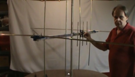 6m/2m/70cm Yagi Antenna Built from Old TV Antenna This turned out to be a great little antenna. It works the 6 meter, 2 meter and 70 centimeter bands. You can use one common feedpoint or two seperate feedpoints depending on how you would like to connect this antenna to your transceiver.
 -
 The Icom AH-4 autotuner operates efficiently across multiple HF bands, providing seamless automatic tuning for antennas from 3.5 MHz to 54 MHz. Its robust design allows for outdoor installation, making it suitable for field operations and fixed stations. The unit interfaces with Icom transceivers via a control cable, enabling automatic band switching and tuning. The AH-4 is capable of handling up to 120 watts of RF power, ensuring compatibility with most amateur radio setups. Its weather-resistant casing and compact form factor make it a versatile choice for operators requiring reliable performance in diverse environments. Field tests demonstrate the AH-4's ability to maintain low SWR across its operational range, enhancing signal quality and transmission efficiency. Compared to manual tuners, the AH-4 offers significant time savings and ease of use, particularly in rapidly changing band conditions. Its integration with Icom radios simplifies operation, eliminating the need for manual adjustments. The autotuner's performance is consistent with other high-end models, providing a cost-effective solution for amateur operators seeking dependable tuning capabilities without sacrificing performance.
 -
 A DIY Automatic Band Decoder (ABD) project, designed for dual-radio operation, addresses the common challenge of integrating band data with older transceivers lacking dedicated outputs. This particular build utilizes an AVR AT90S8515 microcontroller and a 16x2 Liquid Crystal Display (LCD) to provide band information, specifically targeting Kenwood rigs via a computer's LPT port. The design aims for cost-effectiveness while maintaining functionality, offering a solution for hams seeking to add automatic band switching capabilities to their station without significant expense. The project outlines the core components required, including the microcontroller, LCD, and an enclosure, noting that the Printed Circuit Board (PCB) fabrication and AVR programming might present challenges for some builders. It details the input requirements, such as a four-pin input and PTT for each radio, along with a 13.8V DC power supply. The decoder provides 2x6 outputs capable of sinking 500mA, suitable for controlling external devices like antenna switches or filters. Despite the original unit being damaged by a lightning strike in 2004, the author confirms its successful operation prior to the incident and mentions plans for a revised version. The resource includes a schematic in PDF format and images of the finished PCB and assembled unit, demonstrating the practical implementation of the design.
 -
 The Buddipole Deluxe, a portable HF/VHF antenna system, receives a practical assessment from IW5EDI after a month of field use. The author, constrained by antenna restrictions, highlights the system's crucial role in enabling portable operations, even managing sporadic digital activity from a balcony. Direct comparisons to a fixed 3-band dipole reveal surprisingly comparable signal reports on 15, 17, and 20 meters, underscoring the Buddipole's effectiveness in real-world scenarios. Tuning the Buddipole proves straightforward on bands down to 20 meters, though the review notes significant challenges with SWR on lower bands like 40 meters, where achieving better than 3:1 SWR was problematic. Observations also include SWR variations with dipole rotation and mast height, suggesting environmental factors play a role. The overall manufacturing quality of the antenna and its accessories, including the tripod and carry bag, is deemed good, despite a minor issue with a pole connector. Looking ahead, the author plans to construct a homemade Buddipole version, possibly optimized for the 30-meter band, specifically for PSK31 operations from an apartment. This personal project reflects a common amateur radio practice of adapting commercial designs for specific needs, further extending the utility of portable antenna concepts.
 -
 A 70 cm yagi designed for EME + SSB narrow bandwidth version, strictly G/T breeding. This little Yagi has a high F/B, which makes it quite useful as a contest stack
 -
 This kind of antenna has grown in popularity over the last years because it gives you a decent performance and triband capabilities. But its 50 MHz design is far from optimal. Here you can learn how to improve its 50 MHz performance in a very easy way.
 -
 About windom antennas and OCF dipoles, tricks on covering more bands moving feed-points and potential problems. Problems caused by common mode currents in OCF dipoles
 -
 Demonstrates the swift setup process for a **Trans World Antenna**, showcasing its utility for portable amateur radio operations. The video highlights the antenna's design for quick deployment, a critical factor for activations like Summits On The Air (SOTA) or Parks On The Air (POTA), where efficiency in establishing a station is paramount. It illustrates the physical components and the sequence of assembly, emphasizing ease of use in varied field environments. The antenna system is presented as a multi-band solution, capable of operating across various HF frequencies. This adaptability makes it a versatile choice for hams engaging in outdoor activities or emergency communications. The visual demonstration provides practical insights into managing the antenna elements and feedline for optimal performance during temporary deployments. The focus remains on the practical aspects of field setup, rather than detailed technical specifications or performance metrics.
 -
 Refurbishing my 10 years old Cushcraft A3S triband HF Antenna