Search results
Query: am antenna
Links: 1696 | Categories: 131
Categories
- Antennas > 40M > 40 meter Magnetic Loop Antennas
- Antennas > 6M > 6 meter J-Pole Antenna
- Radio Equipment > Amateur Radio Accessories
- Software > Antenna analysis
- Manufacturers > Antenna Analyzers
- Antennas > Antenna Books
- Manufacturers > Antenna Masts and Mounts
- Shopping and Services > Antenna Mount
- Manufacturers > Antenna Parts
- Shopping and Services > Antenna Parts
- Manufacturers > Antenna Rotators
- Software > Antenna rotor control
- Manufacturers > Antenna Switches
- Shopping and Services > Antenna Tower Erectors
- Manufacturers > Antenna Tuners
- Manufacturers > Antennas
- Antennas
- Shopping and Services > Antennas
- Operating Modes > Ham Radio Balloons
- Shopping and Services > Ham Radio Insurance
- Shopping and Services > Ham Radio Stores
- Antennas > HexBeam
- Manufacturers > Antennas > HF > HexBeam
- Radio Equipment > HF Vertical Antenna
- Manufacturers > Antennas > VHF UHF Microwave > HT Antennas
- Shopping and Services > Antennas > Microwave Antenna
- Manufacturers > Antennas > VHF UHF Microwave > Microwave antennas
- Manufacturers > Antennas > VHF UHF Microwave > Mobile Antennas
- Manufacturers > Antennas > VHF UHF Microwave > Quad Antennas
- Manufacturers > Antennas > VHF UHF Microwave > Satellite antennas
-
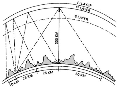
 137 kHz propagation analysis details ground wave and sky wave mechanisms, drawing heavily from **CCIR Rec. 368-6** for ground wave field strength predictions and **CCIR Rep. 265-7** for sky wave modeling. The resource presents field strength values for 1 W ERP at varying distances, considering ground conductivity and permittivity for ground wave, and ionospheric height (70km daytime, 90km nighttime) for sky wave. Key factors like ionospheric focusing (factor "D"), reflection coefficient ("RC"), and antenna ground pattern factors ("Ft", "Fr") are quantified for 137 kHz, enabling calculation of sky wave field strength. Practical coverage ranges are derived for 137 kHz, showing useful ground wave coverage up to 1600 km over seawater and 1100 km over average ground, assuming a -9 dBuV/m noise floor. Sky wave coverage extends beyond 2200 km during night-time and winter daytime, but is negligible during summer daytime at solar minimum. The document also compares ground wave and sky wave strengths, identifying crossover distances at 550 km (night-time), 750 km (winter daytime), and 1250 km (summer daytime), where interference fading can occur. Adjustments for solar maximum conditions are provided, indicating 2-11 dB higher sky wave values depending on distance and season.
 -
 Commsaudit uk, i/q quadrature , hf receivers, rf, multicoupler, multicouplers, switch matrix, antenna matrices, masthead amplifier,, vhf receiver, uhf,
 -
 An easy to build and extremely high performance antenna, works perfectly on all HF bands 3.5-28 MHz with some compromises, it is basically an half wave dipole for 40-80 meters, an LC circuit or trap 40 meters allows you to use a single radiating element.
 -
 eHam reviews on Cushcraft MA5B Mini Beam antenna
 -
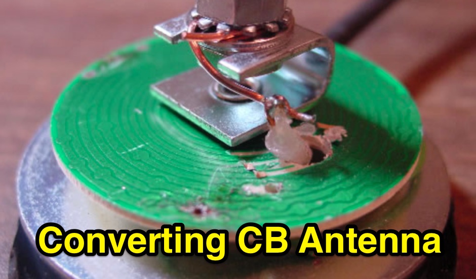 Converting a little Radio Shack CB mobile magnet mount antenna to a VHF ham radio antenna
 -
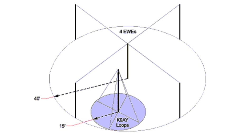
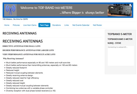 A review of all possible receiving antennas for top band 160 meters
 -
 Sell used low band, mid band and hi band vhf radios and mobile antennas. Used Radio Sales can program these radios to suit your needs.
 -
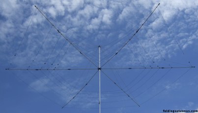 Ultra portable and lightweight folding beam antennas based on G3TXQ design
 -
 A simple, cheap and easy to build 26 feet long vertical antenna that works DX on 20 - 10 meters including WARC Bands, it is designed for portability for field days, camping, or permanent installation, cost, and to achieve at least 1/2 wavelength on the WARC bands.
 -
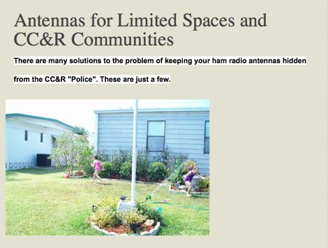 In this article you can find solutions to the problem of keeping your ham radio antennas hidden from the CCR Police
 -
 Announces the retirement of Brand Electronics, a manufacturer specializing in **power meters** and various ham radio accessories, effective 2025. The company has served the amateur radio community for over 35 years, providing equipment for station setup and operation. The product line historically included accessories compatible with major transceivers from Icom, Yaesu, and Kenwood, alongside components and technical references for homebrew projects. Their offerings supported accurate RF power measurement, crucial for optimizing antenna systems and ensuring legal limit compliance. This notice serves as a final update regarding the company's operational status, marking the cessation of manufacturing and sales activities. The site provides no further details on product support or inventory liquidation.
 -
 The article, "Using 75 Ohm CATV Coaxial Cable," details methods for employing readily available 75-ohm CATV hardline in standard 50-ohm amateur radio setups. It addresses the inherent impedance mismatch and practical considerations, such as connector compatibility, for hams seeking cost-effective, low-loss feedline solutions. The resource specifically contrasts common 50-ohm cables like RG-8, RG213, and _LMR-400_ with 75-ohm hardline, highlighting the latter's lower loss characteristics, particularly at VHF and UHF frequencies. It explores two primary approaches to manage the impedance difference: direct connection with an acceptable SWR compromise and precise impedance transformation. The direct connection method acknowledges that a perfect 1:1 SWR is not always critical, especially when using low-loss coax. For impedance transformation, the article explains the use of half-wavelength sections of coax to reflect the antenna's 50-ohm impedance back to the transmitter, noting its single-frequency effectiveness. It also briefly mentions transformer designs using toroid cores and a technique involving two 1/12 wavelength sections of feedline for broader bandwidth. The content further clarifies the concept of _velocity factor_ for calculating electrical versus physical cable lengths, providing a generic formula for precise length determination. It notes that while half-wave matching is practical for 10 meters and above, it can result in excessively long runs for lower bands like 160 meters, potentially adding **250 feet** of cable. The article also mentions achieving a usable bandwidth of 28.000 MHz up to at least **28.8 MHz** on 10 meters with specific transformation techniques.
 -

-
 W3HH wide-band wire antenna Article in French. The W3HH antenna, also known as the Terminated Folded Dipole (T2FD), is a compact, broadband antenna for amateur radio. It operates at an angle of 20 to 40 degrees and covers frequencies from 3 to 30 MHz. The antenna features a total length of one-third of the wavelength at its lowest frequency and is fed using a 1:4 BALUN transformer for impedance matching. A termination resistor around 390 Ω optimizes performance, making it suitable for various amateur radio applications while being easy to construct and install.
 -
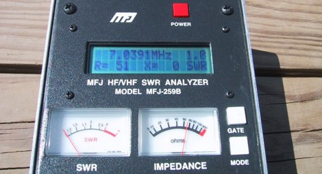 Intermittent fluctuations of SWR readings with MFJ 259B antenna analyzer.
 -
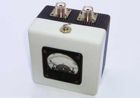 Measuring antenna current with and RF Ammeter
 -
 SPIDERBEAM.US is the exclusive distributor of Spiderbeam antennas, and online shop for USA & CANADA
 -
-
 NRSC AM bandwidth measurements with the loop antenna
 -
 A Tape Measure Beam Antenna for Radio Direction Finding based on WB2HOL design.
 -
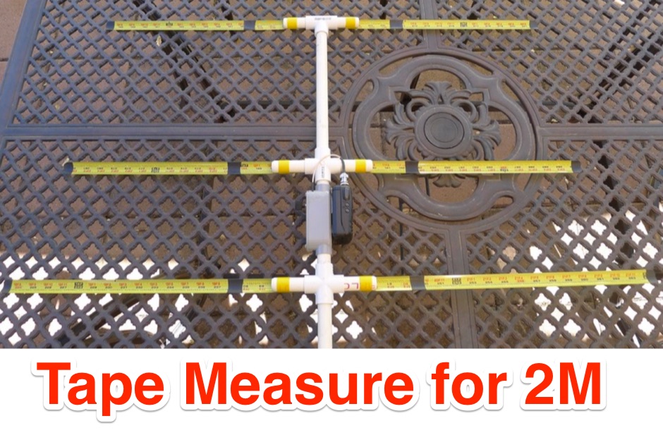
 A 7 dB directional gain is reported for this portable VHF Yagi antenna design, which utilizes cut metal tape measure sections for its elements. The resource details the construction process for a 2-meter band antenna, emphasizing its ease of build and portability. It specifically mentions the design's suitability for radio direction finding (RDF), fox hunting, and communication with satellites and the International Space Station (ISS), highlighting its practical applications for amateur radio operators. The construction cost is estimated at under $20, with potential for even lower expense if salvaged materials like old tape measures and PVC pipes are used. The article references _Joe Leggio's_ (WB2HOL) original design, noting specific alterations made by the author. It also compares this design to other DIY Yagi antennas, including _FN64's_ 2-meter band and _manuka's_ 70-cm band tape measure Yagis, underscoring its unique combination of simplicity, portability, and effective performance with a 1:1 SWR achievable on the 2-meter band.
 -
 1.5 dB of matched line loss can be calculated for a given transmission line using this online tool, which employs a model calibrated from empirical data. The calculator allows radio amateurs to input specific transmission line types, such as _RG-8_ or _RG-58_, and then determine the expected signal attenuation. This is crucial for optimizing antenna system efficiency and understanding power delivery to the radiating element, especially for HF and VHF operations where feedline losses can significantly impact performance. Beyond matched loss, the calculator also provides an estimate for mismatched loss if the Standing Wave Ratio (SWR) is specified. This feature helps operators quantify the additional power loss due to impedance discontinuities between the transceiver, feedline, and antenna, which is a common concern in amateur radio installations. Accurate loss calculations are vital for effective station design and for predicting actual radiated power. The tool's utility extends to various operating scenarios, from fixed station setups to portable deployments, aiding in the selection of appropriate feedline lengths and types to minimize signal degradation. Understanding these losses is a fundamental aspect of maximizing the effectiveness of any amateur radio antenna system.
 -
 Ham radio antenna towers manufactuer based in Italy
 -
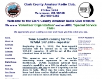 Clark county amateur radio club serving sw washington for 75 years! come find out how our local ham club offers programs that cover everything from the history of morse code and call signs to ham radio antennas
 -
 A page describing how to home made a custom 9:1 balun for a common portable wire antenna. The author suggest to use 4C65 or FT140-61 toroids instead of the common Amidon T200-2
 -
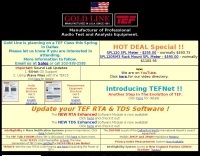 Gold Line, a manufacturer, provides a range of professional audio test and analysis equipment, including specific products like the **ZM1 Impedance Meter**, which is relevant for amateur radio operators needing to characterize antenna systems. The site also lists various noise sources and microphones, such as the TEF04 Mic, indicating a focus on audio signal integrity and measurement. The resource details contact information for repairs, calibration, quotations for specific products like the ZM1 and ZM1P, and technical support, with distinct email addresses and phone numbers provided for each function. This structured contact approach facilitates direct engagement with the appropriate department for specific inquiries. Operational changes effective March 1, 2019, are noted, directing users to VLDESIGN for repair and calibration, and to Partha Chen for ZM1/ZM1P quotations. Louis Pittsley is designated for technical support, with a general inquiry phone number also available, outlining the company's support infrastructure.
 -
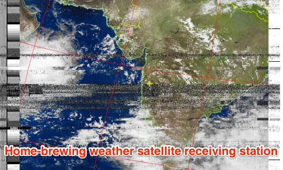 The page provides a detailed guide on how to build your own NOAA weather satellite receiving station, covering hardware, antenna, computer setup, and software installation. It offers a straightforward explanation suitable for beginners and serves as an educational project. The content includes step-by-step instructions and tips for observing satellites in the night sky.
 -
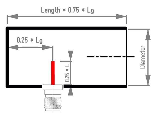 Aka Circular Waveguide Antenna. This online antenna calculator let you plan your cantenna for the desired frequency of operation, giving the Can diameter you have available.
 -
 Two different ways to create autotransformer for end fed half wave wire antennas, by using ferrite or air core.
 -
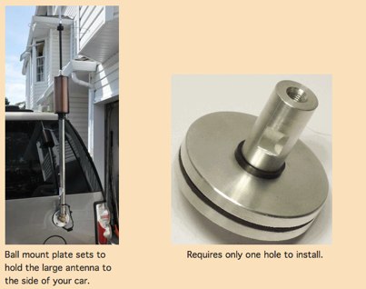 Heavy Duty Antenna Mounts For Mobile Ham Radios
 -
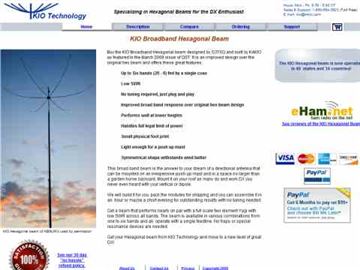 Performance data of the KIO Hexagonal Beam antenna
 -
 An article and buyers guide about antenna anlyzers, undestanding differences among popular RF analyzers in the market
 -
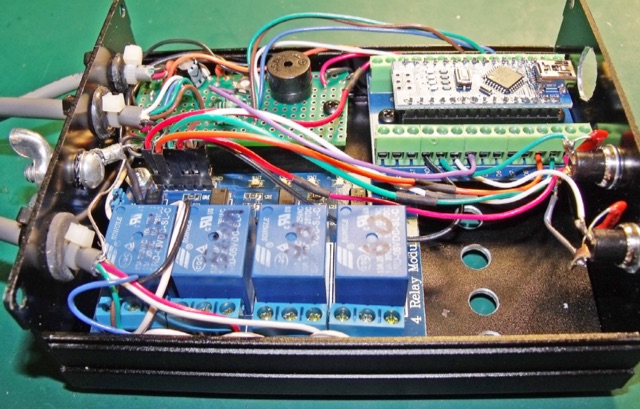 A Programming-Free Automatic Arduino Antenna Switch project published on NCJ
 -
 Amateur radio products,wire and yagi antennas, SDR Receivers, upconverters, pre-amplifiers, towers and RTL funcube dongles by CT1FFU
 -
 Presentation about Practical Antenna Modeling Using the NEC Codes with examples of HF wire antennas and 4NEC2. How to define and edit the models, Running the simulations, Work some examples, Variables usage, Deal with Feed Lines and ground
 -
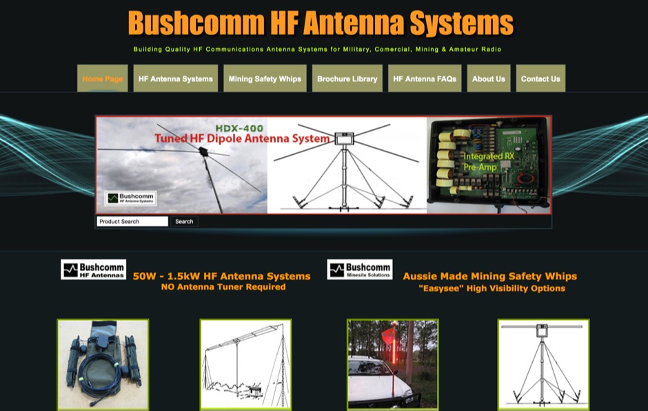 Australian manufacturer of HF Communications Antenna Systems for Military, Comercial, Mining & Amateur Radio
 -
 On this page you will find information about previous, current and future operations of our contest team, different articles, links and info about contesting, DXing, contests calendar, propagation, antennas, equipment, awards, and much more.
 -
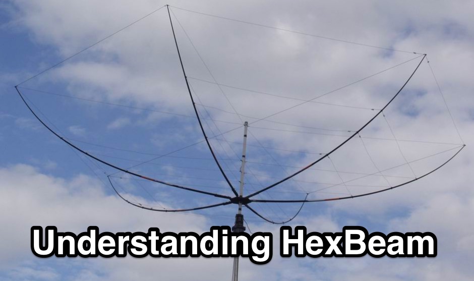 The Hexbeam is a great little antenna! It should be high on your list of options if you want a design that can be multi-banded, exhibits useful gain and directivity, is very lightweight, has a small turning radius, and which lends itself readily to Do It Yourself construction.
 -
 Mobile RFI, often manifesting as persistent noise in the receiver even with the antenna disconnected, frequently originates from the vehicle's power supply system. This guide details systematic troubleshooting steps, beginning with isolating the radio from the car's 12-volt supply to confirm the power system as the noise source. It emphasizes the critical importance of drawing power directly from the battery using **heavy gauge wire**, bypassing the fuse block to leverage the battery's natural capacitance for RFI suppression and ensuring a solid RF ground. Proper routing of power lines through the firewall is also covered, advocating for dedicated grommeted holes to prevent inductive coupling from other wiring harnesses. The article stresses the necessity of fusing both positive and negative leads from the battery, a crucial safety measure to prevent damage to the rig and mitigate high-current risks should the battery's engine block ground become compromised during service. Addressing **alternator whine**, a common high-pitched noise that varies with engine speed, the resource suggests checking battery connections and the alternator-to-battery harness for looseness or corrosion. It also mentions the utility of adding an external RF noise suppression capacitor in parallel with the alternator's internal capacitor for enhanced filtering, and the effectiveness of commercially available in-line power supply filters.
 -
-
 While intended mainly for antenna loading coils, this article also applies to other resonant systems, such as amplifier tank circuits.
 -
 R3KBO is an amateur radio club producing and developing amateur radio kits and assembled products including HF VHF Power Amplifiers or RF Power Kits and amplifier parts, low pass filfers, band pass filters, sourge protections, splitters and combiners, antenna switches
 -
 The antenna in this project is a modification of the techniques used to design a multiband fan type dipole with little or no tuning involved having a total space of 105 feet
 -
 A project for a vertical antenna for 60 to 20 meters by KV5R
 -
 Evaluates the **LDG Z100 autotuner**, a device designed to automatically match antenna impedance for optimal transmission efficiency. The review discusses its performance in comparison to the MFJ-902, noting that while the Z100 is a reliable autotuner, it does not match the range of impedances that the MFJ-902 can handle. The Z100 is suitable for operators seeking a 100-watt autotuner that covers HF bands, providing a practical solution for those who require automatic tuning without manual adjustments. The review highlights the Z100's operational context, focusing on its use in HF bands and its practical application in amateur radio setups. While it offers a straightforward tuning process, the Z100's limitations in impedance matching are noted, making it less versatile than some competitors. This comparison provides valuable insights for operators considering an upgrade or replacement for their current autotuner. The Z100's performance is positioned within the broader market of autotuners, offering a clear perspective on its strengths and weaknesses in real-world amateur radio operations.
 -
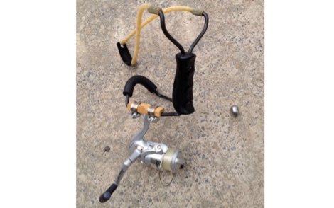 A simple and effective antenna launcher system by AA4LR
 -
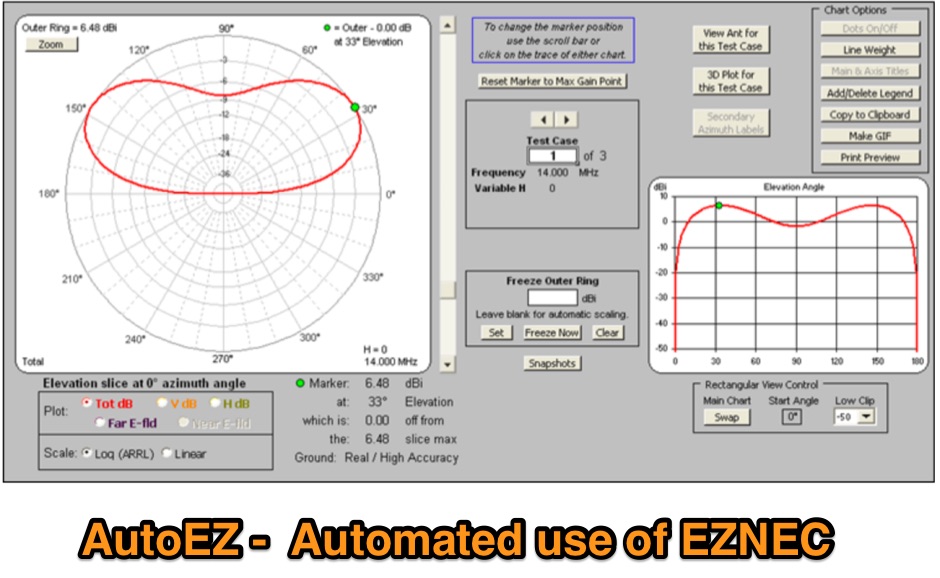 Automated use of EZNEC. AutoEZ is an Excel application that works in conjunction with the EZNEC antenna modeling programs and allows you to use variables to control diverse aspects of the model. You can then run multiple EZNEC test cases while AutoEZ automatically changes one or more variables between runs. Commercial version and free demo available for download.
 -
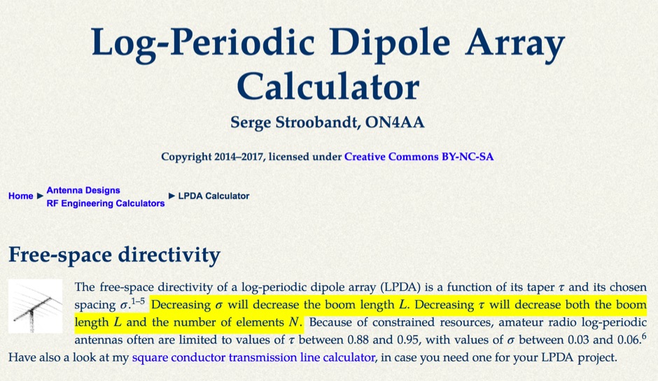 This LPDA calculator is based on the design procedure as described by L. B. Cebik, W4RNL (SK) in the 21st edition of The ARRL Antenna Handbook.
 -
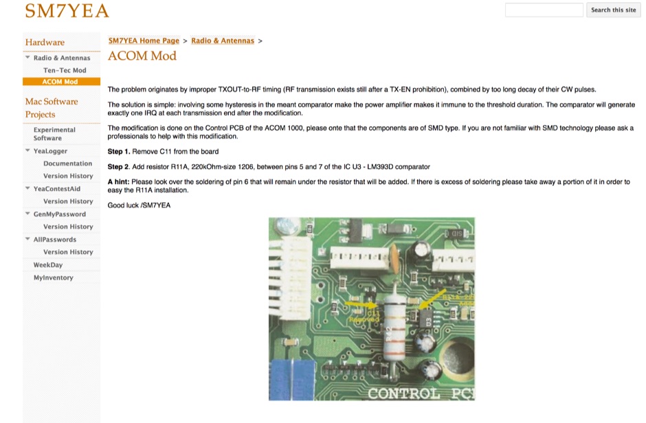 The problem originates by improper TXOUT-to-RF timing (RF transmission exists still after a TX-EN prohibition), combined by too long decay of their CW pulses.
 -
 Cheap but effective multiband quad antenna covering the entire horizon on 10-12-15-17-20m bands.