Search results
Query: circuit design
Links: 124 | Categories: 4
-
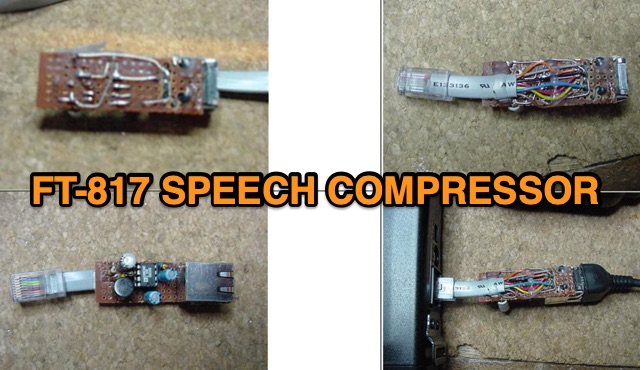 Designed for the FT-817, this audio speech compressor, centered on the Analog Devices SSM2165, offers a 40 dB compression range, enhancing signal power. Built externally with the SMD version to preserve warranty, the circuit interfaces smoothly with electret microphones. Testing shows a 6 dB average power increase. Adaptable to rigs with electret microphones, it maintains unity gain and 40 dB compression.
 -
 Four _Headway 38120_ LiFePO4 cells form the core of an 8AH 12V battery pack, designed for reliable emergency and field power in amateur radio operations. These batteries offer significant advantages over traditional lead-acid types, including a lifespan up to **10x** longer in charge/discharge cycles, lower internal resistance for faster recharging, and a flatter discharge curve that maintains voltage stability during use. Their inherent safety, being a flame-retardant technology, makes them a preferred choice for portable applications. Proper configuration, including parallel/serial setups, and careful charging/discharging protocols are crucial for maximizing battery life. Each cell has a nominal voltage of 3.2 volts, with a maximum charge voltage of 3.65 volts. A Battery Management System (BMS) is highly recommended to prevent overcharging or deep discharging, safeguarding the cells. The project emphasizes safety, noting the batteries' high short-circuit capacity of **200 AMPS** and the critical importance of incorporating an inline fuse between the battery pack and the load. Components like the battery holder, buss bars, and a suitable case are also detailed.
 -
 Chavdar Levkov, LZ1AQ, presents an experimental comparison of small wideband magnetic loops, building on his previous work on wideband active small magnetic loop antennas. His research focuses on increasing loop sensitivity by maximizing the short-circuit current, which is directly tied to the "loop factor" M = A/L, where A is the equivalent loop area and L is its inductance. Levkov's methodology involves reducing inductance and increasing area through parallel or coplanar crossed (CC) configurations, comparing these designs against a reference single quad loop of 1 m2 area. Experimental verification included testing three distinct loop types: a simple quad loop, two coplanar crossed (CC) loops, and eight parallel loops, all designed to have a total geometric area of 1 m2. Measurements were conducted at 1.8, 3.5, 7, and 10 MHz using a small transmitter 270 meters away, with a Perseus direct sampling receiver for precise signal level assessment. The results consistently showed that CC loops, particularly Loop 5 (two CC circular loops with 1.44 m2 total area), yielded significantly higher currents, up to 9.1 dB over the reference loop at 3.5 MHz, validating M as a reliable predictor of loop sensitivity. Numerical simulations using MMANA further corroborated the experimental findings, demonstrating an almost perfect correlation between the calculated M factor and the induced loop current for 15 different loop models. Levkov concludes that CC loops offer superior sensitivity for a given loop area, while parallel loops are advantageous for minimizing physical volume. Practical recommendations suggest using loops with an M factor greater than 0.5 uA/pT for quiet rural environments, and he provides a spreadsheet tool, WLoop_calc.xls, to aid in optimizing loop configurations for specific operational needs.
 -
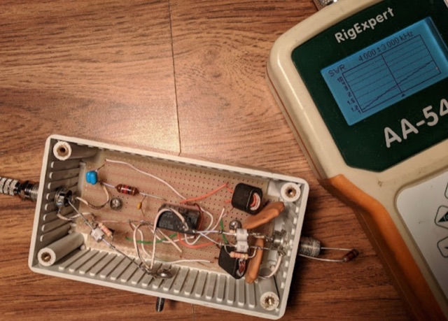
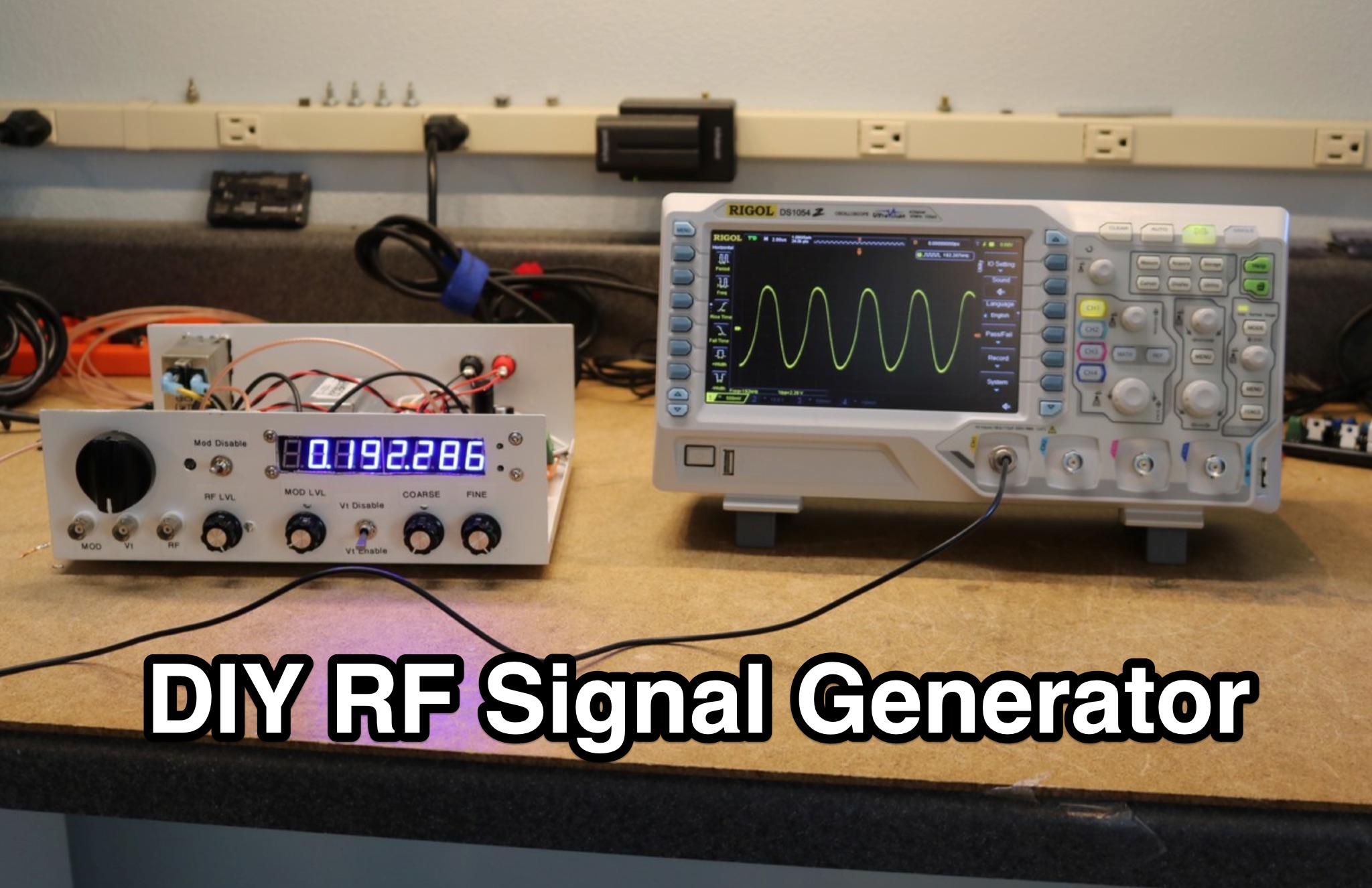 Learn how to build your own RF signal generator for aligning radios by following the modifications made to the circuit of an existing project. Explore the use of a common cathode varactor diode and a single center-tapped 24 VAC transformer to simplify the design. Discover alternative components like the MACOM 4ST079CK-287T varactor diode, which offers cost-effective solutions compared to unobtainable options. Find inspiration in modifying existing projects and gaining practical knowledge in electronics. Purchase the Nuts and Volts magazine for detailed schematics and a deeper understanding of RF signal generators.
 -
 Constructing a double bazooka antenna for the UHF band, specifically tuned for 435 MHz, involves a straightforward process detailed with step-by-step imagery. The design leverages readily available _RG213 coaxial cable_, cut to precise lengths derived from formulas: 140.208 / F (MHz) for the radiating element and 99.06 / F (MHz) for the coaxial section. This approach yields a highly effective vertical polarization antenna, suitable for local ragchewing or repeater access. My own field experience with similar coaxial designs confirms their robustness and ease of deployment. The article emphasizes critical steps like short-circuiting cable extremities, interrupting the braid at the center, and securing an insulating support. It also covers preparing the definitive mounting with a quality feedline, noting that RG58 is acceptable for temporary use but better options exist for permanent installations. Weatherproofing is crucial for longevity, achieved through PVC electrician's tube, glue, and heat-shrink tubing. The final assembly is designed for mounting on a small aluminum mast, with the feedline routed internally. The reported SWR measurement is very satisfactory, showing approximately **+/- 3%** HF return, indicating excellent impedance matching at the target frequency.
 -
 This project details an automatic roger beep circuit for VHF/UHF contests. Built around a Microchip PIC microcontroller, the design detects PTT (Push-To-Talk) activation and generates a brief tone upon release, mimicking a "roger beep" to signal the end of transmission. The circuit utilizes readily available components and includes downloadable resources for PCB layout and firmware.
 -
 Detecting stray RF voltages on station grounds, chassis, and interconnecting cables is crucial for preventing program and hardware failures in the shack. This article details the construction and application of an LED RF V-probe, which offers significantly higher sensitivity compared to conventional neon lamp indicators. The probe leverages two specific properties of modern red LEDs: their ability to glow at microampere currents and their rectification capability at frequencies up to tens of megahertz. The design features a simple circuit with two LEDs, allowing for indication of both positive and negative RF voltage half-waves. The minimum detectable RF voltage is approximately 2 V, a substantial improvement over the 40-60 V threshold of neon bulbs. The resource illustrates the probe's physical construction on a PCB and provides a direct comparison demonstrating its superior sensitivity in detecting RF fields near a coil. Two operational modes are described: a non-contact mode for high RF voltages (above 15-20 V) and a direct-contact mode for measuring lower RF voltages, with a safety caution for the latter. Practical examples show the probe's use in analyzing RF voltage distribution across a radio station setup at 1.84 MHz and 24.9 MHz, revealing insights into common-mode current issues and the effectiveness of mitigation strategies like adding radials.
 -
 The CW keyer with memories, inspired by SOTA activities, features three on-the-fly programmable memories for hands-free operation during logging or specific calls. Designed for low power consumption, it uses AAA batteries and an Arduino Mini, optimized for minimal energy use with a sleep function. The compact design fits in a small TEKO box, with a printed circuit board for easy assembly. The keyer includes customizable software for various CW modes and settings, programmable via paddles and command mode. It's an efficient, portable solution for amateur radio enthusiasts seeking enhanced CW functionality.
 -
 This project features a compact, 5-LED general-purpose S-Meter, designed for use with various radio circuits. It utilizes the LB1403 IC, with alternatives like LB1413, LB1423, and others. The circuit's design allows flexibility, with one version featuring a trimpot for calibration and another without it for more compact setups. The LB1423 is preferred for its low current draw and dB-calibrated scale. This S-Meter offers an efficient, customizable solution for measuring signal strength in amateur radio applications. In Portuguese.
 -
 A dual insert microphone design for the Icom IC-7300 transceiver utilizes a **Besson BZ2400 M4 Rocking Armature** insert for frequencies from 500 Hz to 3 kHz, exhibiting a rising response of approximately 11 dB. A generic Electret Condenser insert, powered by the transceiver's microphone line, covers the low-frequency range from 100 Hz to 500 Hz. A Low Pass Filter is incorporated after the Electret insert to prevent frequency overlap, and a pre-set potentiometer (VR1) adjusts the low-frequency response, balancing the output of both inserts. The design emphasizes a "Close Talking" arrangement and addresses audio "colorization" by housing the Besson insert in a thick rubber holder with a foam boot, separate from the circuitry, with the Electret insert also wrapped in a foam boot. Critical importance is placed on using the correct BZ2400 M4 insert with 12 holes in its face plate. The frequency response table for the BZ2400 M4 insert shows 0 dB at 500 Hz, rising to +11 dB at 3000 Hz, while the Electret insert with the Low Pass Filter provides 0 dB at 100 Hz, rolling off to -9 dB at 500 Hz and -50 dB at 3000 Hz. This combination ensures a broad, balanced audio spectrum for SSB operation. The project includes a circuit diagram, a comprehensive parts list detailing components like a 1 Henry iron-cored inductor (L1) and various capacitors, and a board layout within the metal tube. The completed unit provides a tailored audio profile for the IC-7300, enhancing transmit audio quality.
 -
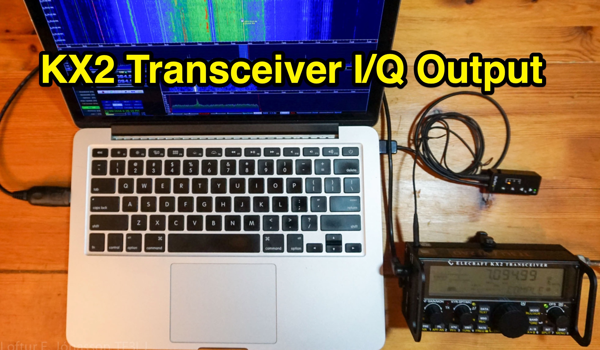 Learn how to add an audio I/Q output to your KX2 transceiver for use with a Spectrum Scope or external SDR software. The article provides a detailed guide on the circuit design and components needed, along with precautions to avoid signal degradation. Follow the instructions to enhance the functionality of your KX2 without compromising its performance.
 -
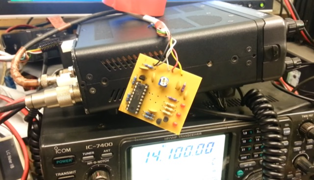
 The project details the construction of a GM3OXX OXO transmitter, designed to accommodate **FT-243 crystals** using 3D-printed FX-243 holders from John KC9ON. It presents specific frequency adjustments, noting a 7030 KHz HC-49/s crystal could be tuned from 7029.8 KHz to 7031.7 KHz with an internal 45pF trimmer capacitor. The build incorporates a modified keying circuit to prevent oscillator run-on key-up and includes a TX/RX switch for sidetone via a connected receiver, with the transmitter output routed to a dummy load on receive. Practical construction aspects are thoroughly covered, including the process of cutting a rectangular opening in a diecast enclosure for the FT-243 socket and the selection of a **low-pass filter** (LPF) based on the QRP Labs kit, derived from the W3NQN design. The author achieved approximately 800mW output power from a 14.75V supply, measured with an NM0S QRPoMeter, using a 16.5-ohm emitter resistor in the 2N3866 final stage. The article also touches upon the potential for frequency agility across the 40M band using multiple FX-243 units with various crystals. The narrative includes a brief diversion into Bob W3BBO's recent homebrew projects, such as his Ugly Weekender MK II transceiver, highlighting the enduring appeal of classic QRP designs. The author reflects on the personal satisfaction derived from building RF-generating equipment, irrespective of DX achievements, and shares experiences of making local contacts with the 800mW OXO transmitter on 40 meters.
 -
 The project details the construction of a small, portable **CW decoder** built around an Arduino Nano and an LM567 tone decoder circuit. It integrates an OLED display for output and is powered by a 1200 mAh Li-Po battery. The Arduino Nano is programmed with a modified version of the OST Morse Box firmware, originally based on Budd, WB7FHC's work, provided as a HEX file for flashing. The LM567 output connects to Arduino pin D2, while pins A6 and A7 are grounded due to the absence of potentiometers, simplifying the circuit. Standard I2C connections are used for the OLED: SDA to A4 and SCL to A5. The entire assembly, including the Arduino, OLED, and decoder circuit, is mounted on a perfboard to fit precisely within an old cassette tape box. This design emphasizes portability and compact form factor. Parameters for the decoder can be adjusted using a dedicated Windows Control program, offering flexibility in operation. The resource provides practical insights into adapting existing firmware for specific hardware constraints and achieving a self-contained, battery-powered **Morse code** decoding solution.
 -
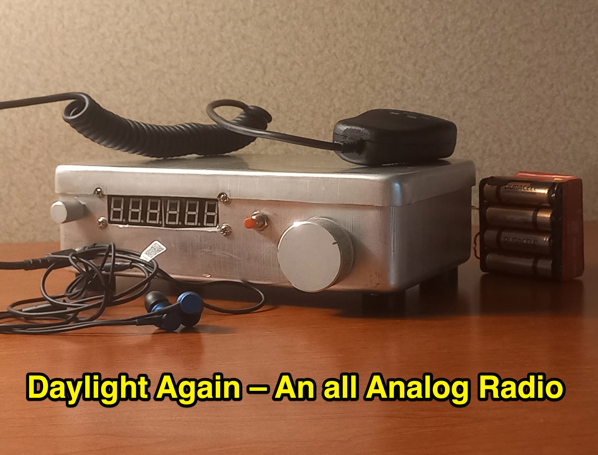 This article discusses a high performance, 7MHz, 5 watt SSB rig, the Daylight Radio, an all-analog radio design from the 1980s that includes a full circuit diagram, IMD NR60 calculations, QER crystal filter, bandpass filter, receiver portion, and more. The author explores the design, components, and functionality of this analog radio for hams interested in vintage or homebrew radio projects.
 -
 Learn how to leverage AI assistants like ChatGPT for designing circuits. Electronics engineers can benefit from using ChatGPT for hardware design projects, especially when facing challenges in the analog domain. Discover how AI can enhance productivity and provide solutions to complex hardware design questions. Explore the future of electronics design with ChatGPT and similar chat assistants.
 -
 The Yaesu VX-6R USB Programming Interface is a reliable solution for programming the Yaesu VX-6R handheld radio using USB. Based on the FT232RL chip, it replaces older RS232 interfaces and USB converters, ensuring stable communication. The design integrates a buffering circuit with a Sparkfun breakout board, featuring TX and RX LEDs for easy monitoring. The compact interface connects to the radio via a four-pin header, with a solder bridge option for radios requiring separate data lines. This setup has proven reliable and versatile, allowing the FT232RL to be repurposed for other projects.
 -
 The Pressure Paddle V2.0 simplifies the original 2019 design by using MOSFETs’ unique properties for reliable, minimalistic switching. When pressure sensors detect a press, they reduce resistance, activating the MOSFET and lowering voltage until it stabilizes at the MOSFET’s threshold. This ensures consistent “key down†signals for the transceiver. Compatible with 3-5V logic systems, the circuit operates independently of pull-up resistor size. The PCB is lightweight, easy to assemble, and can be packaged in heat shrink or mounted. This version maintains durability with fewer components and flexible packaging options.
 -
 The article details how to eliminate Radio Frequency Interference (RFI) from the Behringer HA400 headphone amplifier when used in ham radio setups. While the HA400 is praised for its quality and affordability, it was not designed for RF environments, causing distortion when used with a 500-watt radio station. Initial attempts using clamp-on ferrites on the headphone and power cables only partially resolved the issue. Upon opening the unit, the author discovered the circuit lacked RF bypassing components. The solution involved installing 0.1μF (104) capacitors at key points in the circuit: the power supply input, audio circuits, and op amp inputs. This modification, combined with the external ferrites, completely eliminated the RFI problem, making the unit suitable for ham radio operations.
 -
 This online project documentation details the construction of a hands-free microphone interface unit designed for _mobile_ amateur radio operation. The curriculum covers the integration of electret microphone elements with amateur radio transceivers, specifically addressing **VHF** band communication. It outlines the circuitry for a switch box that provides an interface between various radio models and microphone types. The guide specifies the inclusion of a **1750 Hz** tone-burst generator for accessing amateur radio repeaters, an operational protocol for many VHF systems. Design considerations include the reduction of ambient vehicle noise through an adjustable audio input level control. The project provides schematics and wiring diagrams for connecting the interface unit to specific amateur radio transceivers, including the Yaesu FT-817. It addresses the selection and adaptation of readily available electret microphone and earpiece assemblies, initially sourced from mobile phone accessories, and later from dedicated headset units. The design incorporates a control mechanism for radio functions, enabling hands-free operation during _mobile_ excursions. Circuit details cover power supply considerations for the electret microphone and signal routing for both transmit audio and received audio monitoring. The documentation specifies component selection for the switch box, ensuring compatibility with common amateur radio microphone input impedances and output levels. This includes considerations for PTT line switching and audio path isolation. DXZone Focus: Online Project Documentation | Hands-Free Mobile Microphone Interface | Electret Microphone Integration | 1750 Hz Tone-Burst Generation
 -
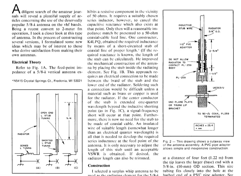 A 5/8-wavelength vertical antenna for 2-meter FM operation is detailed, focusing on eliminating loading coils by utilizing a series inductor to cancel capacitive reactance at the feed point, thereby presenting a 50-ohm impedance match. The design illustrates three basic configurations, including a method employing a short-circuited coaxial stub for inductance, as implemented by K4LPQ. An alternative design is presented where the center conductor of the stub is extended one-quarter wavelength, creating a signal-frequency short and allowing for an insulated wire stub to develop the required series inductance. The article provides electrical theory and mechanical considerations for building the antenna, emphasizing the adjustment of stub length for proper impedance matching. This technical documentation is intended for amateur radio operators interested in homebrewing VHF antennas, offering practical insights into impedance matching techniques for vertical radiators.
 -
 The article describes adding lightning protection to Beverage antennas, which are long wires susceptible to lightning strikes. The author reviews common lightning protection circuits and discusses their components. They then detail their design based on existing methods, highlighting choices for components and reasoning behind them. Finally, the author presents the completed design and its implementation on their Beverage antennas.
 -
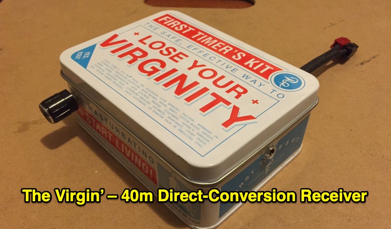 Demonstrates the construction of 'The Virgin', a **direct-conversion receiver** specifically designed for the 40m amateur radio band. This project, completed in February 2016, features a fixed operating frequency determined by a crystal oscillator, requiring a physical crystal change to alter the reception frequency. The design incorporates two integrated circuits and a power regulator, emphasizing simplicity with a single control knob. The author details the initial design, subsequent modifications to the front end, and troubleshooting steps addressing common issues like audio motorboating and power supply instability. The resource presents the final design of the receiver, reflecting the author's first experience building such a unit between December 2015 and February 2016. It offers practical insights into basic circuit construction and the iterative process of refining a homebrew radio project. The content is particularly relevant for those interested in fundamental receiver principles and hands-on **QRP** transceiver building.
 -
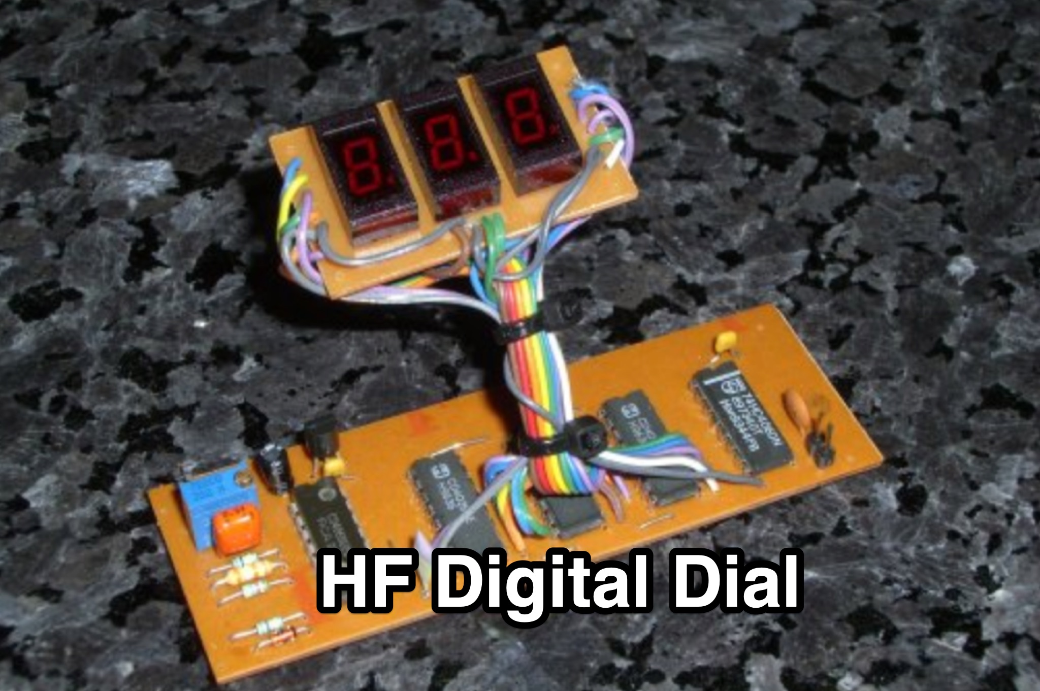 This page by Andrew Woodfield ZL2PD provides information on CMOS HF Digital Dial for hams. It covers design options, circuit description, construction, alignment, and operation. The page also includes references and downloads. Whether you're looking to build or understand a digital dial for your HF rig, this page offers valuable insights and resources.
 -
 Demonstrates the construction of an active loop converter specifically designed for the Low Frequency (LF) bands, addressing common localized noise interference in LF reception. The design integrates a sharply tuned circuit and a tuned loop antenna, utilizing the loop as the sole tuned inductive element. By applying positive feedback, the converter significantly increases the loop's effective Q, achieving factors between 1000 and 2000, which sharpens tuning and reduces noise. The circuit employs an _NE602_ mixer stage, feeding its output to an HF receiver, with a crystal-locked local oscillator at 4 MHz. A 20-turn, 0.8-meter square loop antenna with 500 uH inductance is detailed, connected via 2 meters of figure 8 flex cable. The converter offers three selectable frequency bands: 195-490 kHz, 150-220 kHz (including the New Zealand amateur band), and 128-160 kHz (covering the European amateur band). Performance measurements indicate an effective 3dB bandwidth of approximately 100 to 200 hertz at 200 kHz. The article provides insights into component selection, including an _LF353_ op-amp and a trifilar wound transformer on a ferrite core. Sensitivity figures are presented, showing 7.5 uV of converted output per 1 uV/meter signal strength into a 50-ohm load, or 37.5 uV into an _FRG7_ receiver, highlighting its capability to extract weak signals from noise.