Search results
Query: eme antennas
Links: 222 | Categories: 2
-
 Antenna tuners are crucial for matching the impedance of antennas to the 50 ohm output impedance of transmitters. The _LDG Z-11 Pro_ is an automatic antenna tuner designed to handle up to 125 watts, making it suitable for a wide range of amateur radio applications. Its compact form factor allows it to pair well with transceivers like the _FT-857D_, providing a portable solution for operators who frequently change locations or setups. The tuner covers the 80 through 6 meter bands, offering a broad impedance match capability. Although it struggles with some loads, it performs well with typical ham antennas, even managing to load an 80 meter dipole on 6 meters. One of the standout features of the _Z-11 Pro_ is its 8000 memory slots, which enable it to remember successful matches and quickly retune when revisiting frequencies. This memory function significantly reduces tuning time, often to less than half a second. The unit is well-constructed, with improved pushbuttons and a sturdy metal case that offers good shielding. However, users should be aware of potential RFI issues and the lack of a power switch, which requires disconnecting the power cord to turn off the unit completely. Overall, the _LDG Z-11 Pro_ is a user-friendly and cost-effective tuner, offering advanced features that enhance its utility in various amateur radio setups.
 -
 Operating magnetic loop antennas requires careful consideration of RF safety, particularly regarding near-field magnetic field intensity. This resource presents calculations for magnetic field strength (H-field) at various distances from a magnetic loop, emphasizing that the H-field is significantly higher than the E-field in the near-field region due to the inductive nature of the radiating element. It provides specific formulas and examples for determining safe operating distances based on power levels and loop dimensions, crucial for compliance with RF exposure limits. The analysis compares calculated H-field values against FCC and ICNIRP maximum permissible exposure (MPE) limits for controlled and uncontrolled environments. It demonstrates that even at QRP power levels (e.g., 5W), the H-field can exceed MPE limits within a few feet of the antenna, necessitating greater separation distances than often assumed for electric field considerations. The practical application of these calculations helps amateur radio operators configure their stations to ensure personnel safety and regulatory compliance when deploying compact, high-Q magnetic loop antennas.
 -
 DK7ZB's fan dipole designs address the challenge of operating multiple HF bands with a single feedline, providing practical construction details for **multiband wire antennas**. The resource outlines specific lengths for half-dipoles across various band combinations, including 10-15-20m for classic bands and 12-17-30m for WARC bands. It emphasizes the importance of proper spacing between resonant elements to avoid impedance interaction and high SWR, a common issue when frequencies are too close. The article details the use of **current baluns** built with FT240-43 or FT140-43 cores, specifying turns and cable types for 1KW and 400-Watt power levels. It includes a correction table for adjusting dipole lengths based on frequency shifts, aiding in fine-tuning resonance. The 20+40m dipole is noted for its ability to operate on 15m with an ATU, demonstrating versatility.
 -
 Hi-Z Antennas offers specialized high-impedance receiving systems, primarily focusing on phased vertical arrays for HF reception. Their product line includes preamplifiers designed for shortened vertical antennas, featuring optimized 15dB gain and array-matched characteristics. These components are engineered to enhance weak signal reception and improve signal-to-noise ratio across the HF spectrum. The company provides controllers for managing multiple vertical elements in a phased array configuration, enabling directional reception patterns. These systems are particularly effective for mitigating local noise and interference, a common challenge in urban and suburban operating environments. Specific offerings include solutions for 160-meter and 80-meter bands, addressing the unique requirements of low-band DXing. Technical details often reference components like the 2N3866 transistor in preamp designs and discuss concepts such as out-of-band attenuation. The focus remains on optimizing receiving antenna performance through impedance matching and active amplification, rather than transmit capabilities.
 -
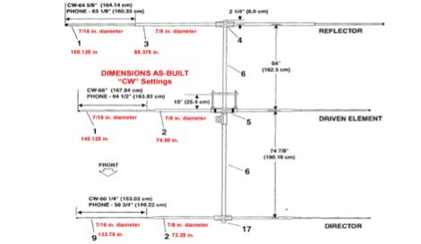
 Based on a simple project based on a 2 elements Yagi for 20m band, and then becomed a triband yagi with a open-sleeve feed system
 -
 The HyGain LJ-153BA a monoband 3 element Yagi, designed for the 15 m band 21.00 - 21.45 MHz
 -
 **LDG Z100** automatic tuner repair focuses on toroid replacement and troubleshooting. The guide provides detailed steps for diagnosing and fixing common issues with the toroid, which is crucial for the tuner's performance. It includes specific instructions on disassembling the unit, identifying faulty components, and sourcing replacements. The document is technical, requiring familiarity with electronic components and soldering techniques. It emphasizes the importance of using the correct toroid specifications to ensure optimal functionality. Successful repair of the **LDG Z100** ATU restores its ability to match a wide range of antennas, enhancing transmission efficiency. The guide compares the performance before and after the repair, highlighting improvements in SWR readings and overall reliability. Practical application of this repair extends the life of the tuner, making it a cost-effective solution for amateur radio operators. The document serves as a reference for similar repairs on other models, providing insights into common issues and solutions. It is a valuable resource for those looking to maintain their equipment without resorting to professional services.
 -
 50 MHz extended 6-7 element ZX-Yagi antenna. Dimensions for the 7 elements and information on performance of a 2 stacked antennas featuring a total max gain of 20.8 dBi
 -
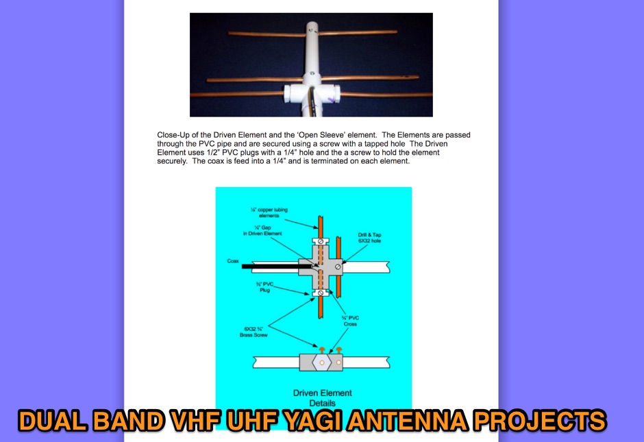 On this page are designs for Dual Band 2M / 70cm antennas. All antennas are 50 ohm designed driver. These Yagis have a unique element called a Open Sleeve. 4 Element 5 element and 9 element Dual Band - 2M / 70cm antenna projects
 -
 An excel spreadsheet that in a really simple way checks how much to trim your antenna elements. Download the xls file and watch the presentation video include in this page
 -
 Demonstrates a range of specialized radio frequency equipment and consulting services for amateur and professional applications. The offerings include _Vector-Finder_ direction finding antennas, various test equipment such as _gate dip meters_ and RF sniffers, and communications receiving adjuncts. Additionally, the company produces satellite antennas for weather satellite reception, voice amplification devices like the _Flex-Mike_, and custom prototype circuit boards. The company's product line addresses needs for precise RF measurement, signal detection, and specialized antenna systems, particularly for direction finding and satellite communications. Their historical association with National Radio (HRO) suggests a legacy in radio technology. The site also highlights a subsidiary, Sierra Mountain Products, which offers outdoor recreational gear, indicating a diversification beyond core RF manufacturing.
 -
 This antenna was designed for the CQ WW CW 2009 at EA8URL. All elements are made out of fishing rods with an insulated copper cable fixed on the rods by cable ties. Both fishing rods and cable are UV resistant.
 -
 This is about Small Antenna types and their properties which can help choosing proper antenna for high-frequency wireless communications as: two-way radio, microwave short links, repeaters, radio beacons or wireless telemetry
 -
 Optimizing weak signal reception on the HF bands, particularly in the presence of strong local QRM, often necessitates specialized receiving antenna systems. This resource details the _HI-Z Antennas_ product line, focusing on phased vertical arrays designed for superior noise rejection and directivity. It covers components such as the 4-Square and 8-Element array controllers, which allow for rapid switching of receive patterns, and dedicated low-noise preamplifiers to improve system sensitivity. The site also presents various bandpass filters, crucial for mitigating out-of-band interference and enhancing the dynamic range of the receiver. The HI-Z systems are engineered to provide significant front-to-back and side rejection, often yielding **20-30 dB** of attenuation to unwanted signals, which is critical for DXing and contesting. Users can achieve a notable reduction in local noise, allowing for the discernment of signals that would otherwise be buried. The array controllers facilitate quick pattern changes, enabling operators to null out interference or peak weak signals from distant stations, effectively extending the reach of their receive capabilities by improving the signal-to-noise ratio.
 -
 Operating the _Icom IC-746_ HF/VHF transceiver often presents specific technical questions, and this resource compiles a comprehensive Frequently Asked Questions (FAQ) document in an ASCII text format. It details common inquiries and solutions related to the rig's functionality, accessories, and potential modifications. The content is structured into distinct sections addressing general information, power supplies, antennas, microphones, keyers, amplifiers, TNC integration, and optional IF filters. The FAQ provides practical guidance on topics such as configuring the internal automatic antenna tuning unit (ATU), selecting appropriate power supplies, and understanding microphone pin-outs. It also delves into advanced subjects like computer control via CI-V, wiring for PSK31 operation, and troubleshooting common issues like low S-meter readings on 2m FM or loose tuning shafts. Specific questions cover the installation of optional IF filters, comparing Inrad versus Icom filters, and optimizing filter combinations for various modes. Furthermore, the document outlines various hardware and firmware modifications, including those for increasing monitor volume, replacing LCD driver transistors, and implementing a "poor man's TCXO." It even touches upon untested modifications, such as replacing PIN diodes in the demodulator. The FAQ also lists manual errata and discrepancies, offering a robust knowledge base for IC-746 owners seeking to optimize their station or resolve operational challenges.
 -
 The **TransWorld Antennas TW2010 Traveler HF Portable Vertical Antenna** assembly video provides a visual walkthrough for deploying this popular portable HF antenna. It details the step-by-step process, from unpacking components to final setup, which is crucial for operators preparing for field day operations or DXpeditions. The video focuses on practical aspects, showing how to connect the various elements and secure the antenna for optimal performance. Operators often seek clear assembly instructions for portable antennas like the TW2010 to ensure quick and correct deployment in diverse environments. This visual aid helps clarify potential ambiguities found in written manuals, illustrating the proper handling of the antenna's radial system and telescopic elements. The video serves as a valuable resource for those aiming to achieve efficient operation with the **TW2010 Traveler** in a portable setting. Understanding the assembly sequence can significantly reduce setup time and prevent common errors encountered during initial deployments.
 -
 Demonstrates the swift setup process for a **Trans World Antenna**, showcasing its utility for portable amateur radio operations. The video highlights the antenna's design for quick deployment, a critical factor for activations like Summits On The Air (SOTA) or Parks On The Air (POTA), where efficiency in establishing a station is paramount. It illustrates the physical components and the sequence of assembly, emphasizing ease of use in varied field environments. The antenna system is presented as a multi-band solution, capable of operating across various HF frequencies. This adaptability makes it a versatile choice for hams engaging in outdoor activities or emergency communications. The visual demonstration provides practical insights into managing the antenna elements and feedline for optimal performance during temporary deployments. The focus remains on the practical aspects of field setup, rather than detailed technical specifications or performance metrics.
 -
 A 2 elements delta loop antenna for 14 MHz with a MMana simulation file, dimensions, pictures of this aluminium tube based delta loop antenna, and matching system details.
 -
 A presentation of the Yagi Antennas, and other interesting tid-bits by Brian Mileshosky. The document provides an in-depth exploration of the Yagi-Uda antenna, detailing its historical development, design principles, and performance characteristics. Originally described in the 1920s, the Yagi antenna features a driven element and parasitic elements, including reflectors and directors, which collectively determine its behavior. The document highlights how element lengths, diameters, and spacing influence gain, impedance, and directivity. It also discusses the antenna's reciprocal nature and presents data on typical gain values for various element configurations. Additionally, the text covers practical considerations, such as the construction of a "Tape Measure Yagi" for amateur use, and touches on related antenna types like dipoles and their application in Near Vertical Incident Skywave (NVIS) communication.
 -
 How do two-wire reversible direction Beverages work, an excellent document that explains fundamentals of beverage antennas. This article details the design and performance of a reversible beverage antenna. Leveraging orthogonality between common mode and differential mode currents on a 2-wire line, this antenna facilitates independent reception from both ends. While common mode signals arrive and are summed on a transformer's secondary for common mode reception, differential mode signals induce anti-phase currents, providing individual reception. Various measurements explore impedance, transmission loss, and F/B ratio, highlighting the antenna's effectiveness and areas for improvement. Notably, increasing the antenna's height significantly improved performance.
 -
 Constructing a compact directional antenna for the 17-meter band, this resource details the build process for a Moxon rectangle, a two-element Yagi variant with folded-back elements. It covers the antenna's evolution from the _VK2ABQ beam_ and provides specific dimensions for a version built using fishing pole whips. The content includes a discussion of the antenna's radiation pattern, feedpoint impedance, and its inherent front-to-back ratio, which is often superior to a standard two-element Yagi. Practical considerations for element spacing and material choices are also addressed, alongside a visual representation of the antenna's physical layout. Performance data presented includes a comparison showing the Moxon rectangle's **2.5 dB gain** over a half-wave dipole and a front-to-back ratio of **20 dB**. The resource also touches upon the antenna's relatively wide bandwidth for a two-element beam and its suitability for portable operations due to its compact footprint. It offers insights into optimizing the design for specific operating conditions and discusses the advantages of its lower take-off angle compared to omnidirectional wire antennas, making it effective for DX contacts on the 17-meter band.
 -
 The Superantennas MP-1 portable HF antenna is analyzed for its design and field performance, particularly its high-Q loading coil and 3/8-inch mounting. The review details the antenna's construction, including an 8-inch vertical section, a large-diameter loading coil tuned by a sleeve, and a 4-foot whip that disassembles into six rods for transport. Initial testing with the supplied 10-foot ribbon cable "ground plane" yielded poor SWR and RF hot conditions, indicating an inadequate ground system. Further experimentation with longer radials and resonant counterpoises for each band improved matching and eliminated RF hot issues, but introduced significant operational complexity. The author notes the difficulty in optimizing both counterpoise length and coil setting without an antenna analyzer, and the sensitivity of the MP-1 to counterpoise deployment. The review also discusses the recommendation to tune for maximum received signals rather than minimum SWR, often necessitating an external ATU due to the antenna's typical low impedance. The **MP-1**'s critical dependence on resonant counterpoises for effective operation, especially when elevated, is highlighted as a major drawback for portable use. The author ultimately sold the antenna, concluding that despite its sound technical design, its fussy nature and the need for extensive counterpoise management or an ATU detract from its portability and convenience compared to simpler, less expensive dipole solutions. The **Superantennas MP-1** is deemed a flawed portable antenna, requiring considerable effort to achieve its claimed performance.
 -
 Three Yagi antennas for the six meters band by 9A7PJT. Include a 4 element yagi, a custom design 4 element, and a 5 element yagi with antennas pictures and design.
 -
 The construction principles for open-sleeve elements in antennas
 -
 A 7 dB directional gain is reported for this portable VHF Yagi antenna design, which utilizes cut metal tape measure sections for its elements. The resource details the construction process for a 2-meter band antenna, emphasizing its ease of build and portability. It specifically mentions the design's suitability for radio direction finding (RDF), fox hunting, and communication with satellites and the International Space Station (ISS), highlighting its practical applications for amateur radio operators. The construction cost is estimated at under $20, with potential for even lower expense if salvaged materials like old tape measures and PVC pipes are used. The article references _Joe Leggio's_ (WB2HOL) original design, noting specific alterations made by the author. It also compares this design to other DIY Yagi antennas, including _FN64's_ 2-meter band and _manuka's_ 70-cm band tape measure Yagis, underscoring its unique combination of simplicity, portability, and effective performance with a 1:1 SWR achievable on the 2-meter band.
 -
 A delta loop antenna for 20 meters band designed with MMana with a tuning system made in a classic stub configuration
 -
 SPX Communication Technologies, operating under the TCI International brand, presents a range of radio frequency (RF) solutions primarily for government, defense, and commercial sectors. The offerings include advanced systems for spectrum monitoring, communications intelligence (COMINT), and high-frequency (HF) and medium-frequency (MF) broadcasting and communication antenna systems. Specific product lines encompass _Blackbird_ COMINT systems, _Scout_ spectrum monitoring receivers, and various antenna arrays designed for robust performance in challenging RF environments. The resource details the capabilities of these systems, such as wideband signal detection, direction finding (DF), and signal analysis, crucial for intelligence gathering and regulatory compliance. It also highlights the engineering behind their antenna designs, which are optimized for specific frequency ranges and operational requirements, including high-power broadcast applications and secure military communications. The information presented emphasizes the integration of hardware and software for comprehensive RF situational awareness. The company's focus on empowering partners to "Command the Spectrum" underscores its commitment to delivering critical tools for signal interception, analysis, and management across diverse operational landscapes.
 -
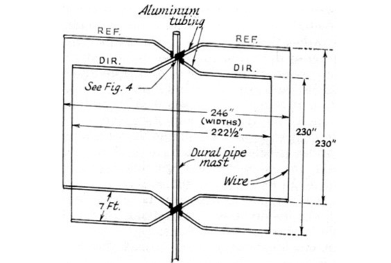
 A Collection of EME Reflector Antennas and YAGI Arrays.
 -
 Pictures, design plan and description of a 5 element yagi antenna for the 4 meters band by 9A7PJT
 -
 This project details the construction and testing of a M0PLK Delta Loop antenna for the 20-10m ham radio bands. Inspired by positive reviews highlighting its reduced local QRM compared to Cobweb antennas, the author built the antenna using aluminum tubes, DX-Wire FS2 wire, and a 1:4 balun. A mix of custom 3D-printed parts and careful assembly ensured stability and performance. Initial VSWR measurements met expectations, and test QSOs demonstrated success across multiple bands. Future enhancements include adding a lightweight, remote-controlled rotator for directional capabilities.
 -
 Constructing a dip oscillator provides radio amateurs with a fundamental piece of test equipment for resonant circuit analysis. This particular design, adapted by VK3YE from a concept by _Drew Diamond VK3XU_, details a practical build using readily available components. The unit incorporates four plug-in coils, covering a frequency range from **2.6 MHz to 55 MHz**, mounted on 5-pin DIN plugs for versatility. A salvaged two-gang air dielectric variable capacitor, fitted with a vernier reduction drive, serves as the tuning mechanism, with the smaller gang optimizing bandspread at higher frequencies. In practical application, the dip oscillator is used by setting the meter needle to approximately two-thirds scale. When the instrument's coil is brought near a tuned circuit under test, a noticeable dip in the meter reading indicates resonance. This allows for precise measurement of resonant frequencies in antennas, filters, and other RF circuitry, proving invaluable for homebrewing and troubleshooting. The design emphasizes short wire runs for stable operation, particularly at the higher end of its operational range.
 -
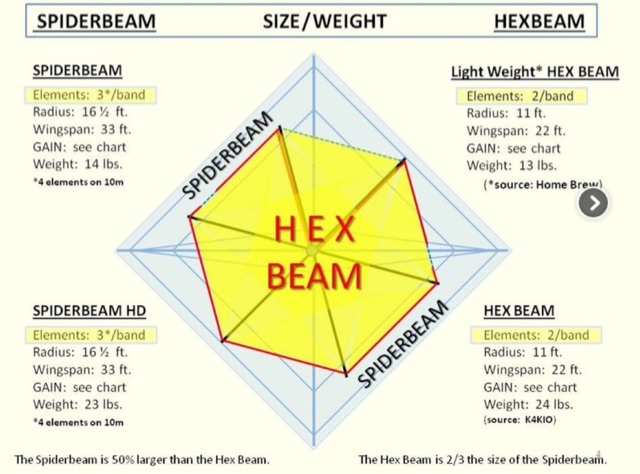 Differences of Hex Beam and Spiderbeam antennas designs, performance and measurements, rotor considerations when using this two kind of antennas
 -
-
 Antenna Authority Inc. offers a wide assortment of directional, wideband antennas and other equipment specifically engineered for radio direction finding (DFing) and geolocation applications. Their product line includes _log periodic_, _cavity-backed spirals_, and _Yagi_ antennas, alongside covert antenna solutions for various operational requirements. The company emphasizes its expertise in designing and manufacturing specialized antennas for both overt and covert operations. Beyond standard offerings, Antenna Authority Inc. provides custom design services to meet specific client needs, focusing on tailored RF directional products. Their capabilities extend to developing antennas for vehicles and optimizing their operational performance in diverse scenarios. The firm is located at 3381 W. County Line Road, Douglasville, Ga. 30135-1145. Ferrel Bentley is associated with Antenna Authority Inc., which has been operating since at least 2005, as indicated by the copyright notice.
 -
 Rotatable Antenna with Phased Elements based on the orignal design concept of HB9CV antennas, is considered to have an higher gain than standard quad antennas. The Swiss Quad Antenna does not need any spreader or boom.
 -
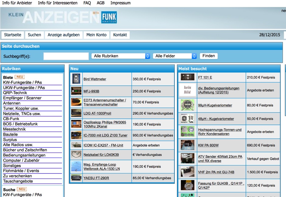 FA-Kleinanzeigen is a dedicated platform for amateur radio enthusiasts in Germany to buy and sell equipment. The site features a wide range of classified ads, including HF and VHF radios, antennas, and accessories. Users can post their listings for free, making it an accessible resource for both seasoned operators and newcomers looking for second-hand gear. The platform categorizes listings into various sections, such as QRP technology, military radios, and even antique equipment, catering to diverse interests within the ham radio community. In addition to equipment sales, FA-Kleinanzeigen also allows users to search for specific items, making it easier to find rare or specialized gear. The site emphasizes user engagement, encouraging individuals to create accounts for posting ads and interacting with other members. With a focus on the German market, it serves as a valuable resource for local hams seeking to expand their stations or offload surplus equipment. Whether you're looking for a new transceiver or just browsing for interesting finds, FA-Kleinanzeigen is a go-to destination for amateur radio classifieds.
 -
 A great and efficient monoband VHF portable antenna. The article consist of two version of a 12.5 Ohm 3 elements yagi beam antenna plans for the two meter band, a full sized and a shortened version expecially designed for the SSB and CW on 144 MHz.
 -
 The calculator designs the Yagi-Uda antenna based on the DL6WU model with boom correction, following the G3SEK-DL6WU method. It optimizes the antenna for maximum gain and allows adjustment of passive elements without affecting SWR. DL6WU antennas are known for their high gain, minimal sensitivity to nearby objects, and stable performance in various weather conditions.
 -
 Comprod Communications specializes in the design and manufacturing of RF communication solutions, including a comprehensive range of antennas, duplexers, multicouplers, and combiners. The resource details their product categories, which encompass base station antennas, mobile antennas, transit antennas, and disguised antennas, alongside mounting solutions and in-building systems. It highlights the company's 40-year history in adapting offerings to client needs and anticipating industry trends, emphasizing product durability and low maintenance for harsh environments. The company's offerings are presented as high-quality, designed to withstand extreme conditions from Arctic cold to equatorial heat and humidity. The site mentions solutions and technical sales support, training, and site analysis and system design as part of their service portfolio. It also references being a market leader trusted by over 1,000 customers worldwide, positioning itself as a partner for RF communication needs.
 -
 Cmpter Electronics specializes in the design and manufacturing of RF coaxial connectors, RF adapters, and RF cable assemblies, serving diverse applications across datacom/telecom, automotive, instrumentation, aerospace, and defense sectors. Their product line includes RF coaxial terminations, attenuators, and waveguide to coax adapters, catering to specific needs in radio frequency systems. The company also offers precision adapters and connectors, alongside glass beads and test cable assemblies, indicating a focus on high-quality components for demanding RF environments. Their resource center provides valuable information, including an "RF Made Simple" section and a product catalog for download, which assists engineers and technicians in selecting appropriate components. The product named system helps in identifying specific parts, streamlining the procurement process for complex RF solutions. With a comprehensive range of RF coaxial cables and related tools, Cmpter Electronics positions itself as a key supplier for critical infrastructure requiring reliable signal integrity. Their offerings support a broad spectrum of RF applications, from basic connectivity to advanced test setups.
 -
 Details Amphenol's extensive product line, encompassing electrical, electronic, and fiber optic connectors, alongside coaxial and flat-ribbon cable solutions. The company designs, manufactures, and markets these interconnect systems globally, serving various communication network requirements. Their offerings support end-to-end connectivity, crucial for modern broadband infrastructure. Emphasizes the company's role as a major provider of components vital for reliable signal transmission in diverse applications. Products like _LMR(R) coaxial cables_ and various _RF connectors_ are essential for amateur radio installations, ensuring low loss and robust connections for antennas and transceivers. The focus on high-performance interconnects directly benefits hams constructing or upgrading their stations. Amphenol's broad portfolio includes specialized connectors and cable assemblies, meeting rigorous technical specifications for both commercial and amateur radio use.
 -
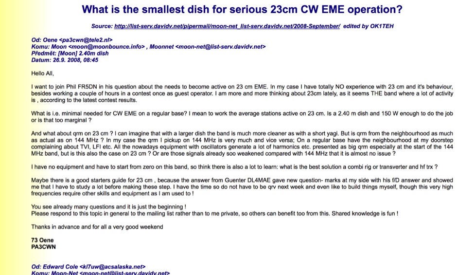 What is the smallest dish for serious 23cm CW EME operation?
 -
 Presents _Beam Quest_, the official Japanese distributor for _SteppIR_ antennas, detailing their product lineup and services. The site showcases various _SteppIR_ Yagi models, including the _Dream Beam_ series (DB42, DB36, DB18E, DB11) with configurations from two to four elements, alongside the _Big IR_ and _Small IR_ vertical antennas. It also lists accessories such as TX/RX and PC interfaces, essential for integrating these advanced antenna systems into a ham shack. Operators often seek out _SteppIR_ antennas for their dynamically adjustable element lengths, which allow for optimization across multiple bands, a significant advantage for DXing and contesting. This adaptability contrasts sharply with fixed-element Yagis, providing a distinct edge in varying band conditions. The resource provides contact information, including email and phone numbers, for inquiries and support regarding _SteppIR_ products within Japan, serving as a direct point of contact for sales and technical assistance.
 -
 Amateur Television (ATV) operations involve transmitting and receiving live or recorded video and audio signals over amateur radio frequencies. Unlike narrow-band modes, ATV utilizes a wider bandwidth to convey video information, often requiring specialized transceivers, antennas, and signal processing equipment. This mode allows hams to share visual content, demonstrate projects, or conduct video conferences, typically on VHF, UHF, and microwave bands due to the bandwidth requirements. The SwissATV resource focuses on the technical aspects and community engagement surrounding ATV within Switzerland. It covers topics relevant to setting up ATV stations, understanding signal propagation at higher frequencies, and participating in local ATV activities. The site serves as a central point for Swiss ATV operators to exchange knowledge and coordinate transmissions, fostering the growth of this specialized amateur radio mode.
 -
 A practical guide on hombrewing Yagi antennas, including notes on Driven Element, Transformation & Symmetrising Coax Lines, Full Boom length vs. electrical length, Elements & Insulators on Boom and additional tips and tricks, in English and German
 -
 Designing and constructing a two-element receiving loop antenna array for HF operation involves specific considerations for achieving high directivity and noise reduction. This resource details a homebrew system comprising two 30-inch diamond-shaped loops, spaced 20 feet apart, which are fed through mast-mounted preamplifiers and passive signal combiners. The operational principle relies on adjusting phase delays between elements via precise _Belden 8241_ coaxial cable lengths, optimized for specific bands from 160m to 20m. Performance data, derived from _EZ-NEC_ modeling, illustrates consistent 90° azimuth-plane beamwidth and low take-off angles across the target bands, with _Receiving Directivity Factor_ (RDF) values comparable to a 300-foot Beverage antenna. The article presents detailed elevation and azimuth plots for 20m, 30m, 40m, 80m, and 160m, demonstrating the array's ability to provide strong response at low DX angles while also supporting _NVIS_ signals. Key components like the _DX Engineering RPA-1_ preamplifier and _DXE RSC-2_ signal combiner are discussed, alongside the importance of impedance matching to preserve antenna patterns. The construction emphasizes self-contained elements that do not require ground radials, offering a compact solution suitable for suburban environments and stealth installations, with a focus on optimizing receive performance independently from transmit antennas.
 -
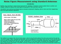 Measuring noise fiugre on the W2IMU horn and the dual-dipole-feed
 -
 Constructing an End-Fed Half-Wave (EFHW) antenna offers a practical solution for HF operators seeking a multiband wire antenna without the need for extensive radial systems. This design typically employs a high-impedance transformer at the feed point, matching the antenna's inherent high impedance to a 50-ohm coaxial feedline. The article specifically details a 2012 approach, focusing on a transformer with a 49:1 turns ratio, which is a common configuration for EFHW antennas. The resource outlines the construction of a wire element cut for a half-wavelength on the lowest desired band, with specific coil arrangements enabling operation on harmonically related bands such as 40m, 20m, and 10m. It discusses the physical dimensions and winding details for the matching transformer, often utilizing a ferrite toroid core to achieve the necessary impedance transformation. The content provides insights into the operational principles and practical considerations for deploying such an antenna, including methods for tuning and optimizing performance across multiple amateur radio bands. While acknowledging that the presented information from 2012 may be superseded by newer insights, it serves as a foundational reference for understanding EFHW antenna theory and construction.
 -
 The video delves into the fascinating science behind antennas, which are crucial for receiving and transmitting electromagnetic waves. It explains how antennas convert electric signals into electromagnetic waves for transmission, and how they operate through the oscillation of positive and negative charges in dipole arrangements. Practical antenna implementations, such as dipole antennas for TV reception and Yagi-Uda antennas with reflectors and directors, are also discussed alongside modern dish TV antennas with parabolic reflectors for signal processing. It's a comprehensive overview of how antennas work and their significance in communication technology.
 -
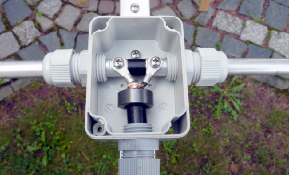
 One of the featured products, the V350 CAMP, is a multiband vertical antenna covering 6 to 80 meters, priced at R$ 799,90, demonstrating the range of ready-to-use solutions available. The inventory includes various antenna types such as **HF**, **VHF**, and **UHF** designs, along with dual-band options like the J-Pole Dual V/UHF for R$ 235,00. For those building their own arrays, the store stocks essential components like element holders, clamps, junction boxes, and aluminum plates, alongside specialized items such as the KIT Isolador Central Dipolo - 01DX for R$ 99,90. The shop also provides a comprehensive selection of installation hardware, including diverse antenna mounts, PTT supports, and various coaxial cables like RG58 and RG213, with prices up to R$ 849,90 for RG213. Connectors such as UHF male PL259 and various adapters are readily available, ensuring compatibility for different setups. Additionally, specialized items like side handles for popular transceivers such as the FT857/891 and IC7300 are offered, catering to specific equipment needs. Beyond antennas, the store supplies practical accessories like transport bags, 12V power cables for transceivers, and even branded merchandise like the Antena Kit mug. Rodrigo Gonçalves, PP5BT, manages the operation from Blumenau, SC, Brazil, providing direct contact via WhatsApp at +55 47 9.9985.0155.