Search results
Query: 10 meter
Links: 502 | Categories: 6
-
 Presents a comprehensive guide for constructing a broadband Hex Beam antenna, a popular directional array for HF operation. This design offers a compact footprint and excellent gain characteristics, making it suitable for limited space installations while providing significant performance advantages over omnidirectional antennas. The resource details the specific dimensions for a five-band Hex Beam covering 20, 17, 15, 12, 10, and 6 meters, emphasizing the critical element spacing and wire lengths required for proper resonance and pattern. It outlines the construction of the center post, spreaders, and wire elements, along with the feed point assembly, ensuring proper impedance matching. The project aims for a forward gain of approximately **5.5 dBi** on most bands, with a front-to-back ratio often exceeding _20 dB_. Building this antenna requires careful measurement and assembly, but the resulting performance provides a substantial upgrade for DXing and contesting.
 -
 Survey of galactic synchrotron radiation at 408 MHz in the south of England using a 10 metre dish and a Dicke radiometer
 -
 30/17/12 and 20/15/10-Meter Tribanders and a 40 meters inverted V wire yagi antenna
 -
 This project outlines the construction of a 3-element reversible quad antenna specifically designed for the 40-meter band. The materials required include pushup towers, pressure-treated posts, insulated wire, and various electrical components such as relays and a balun. The construction process is straightforward, beginning with the installation of the posts in a straight line, followed by the assembly of the antenna elements and their elevation to the desired height. The antenna's design allows for directional signal reception, making it ideal for operators looking to enhance their communication capabilities on the 40-meter band. The project includes detailed instructions on tuning the antenna for optimal performance, ensuring that operators can achieve the lowest SWR possible. Additionally, the design can be adapted for other bands by extrapolating dimensions, providing versatility for amateur radio enthusiasts. Overall, this reversible quad antenna project is suitable for both beginners and experienced operators, offering a practical solution for improving signal strength and directionality in 40-meter communications.
 -
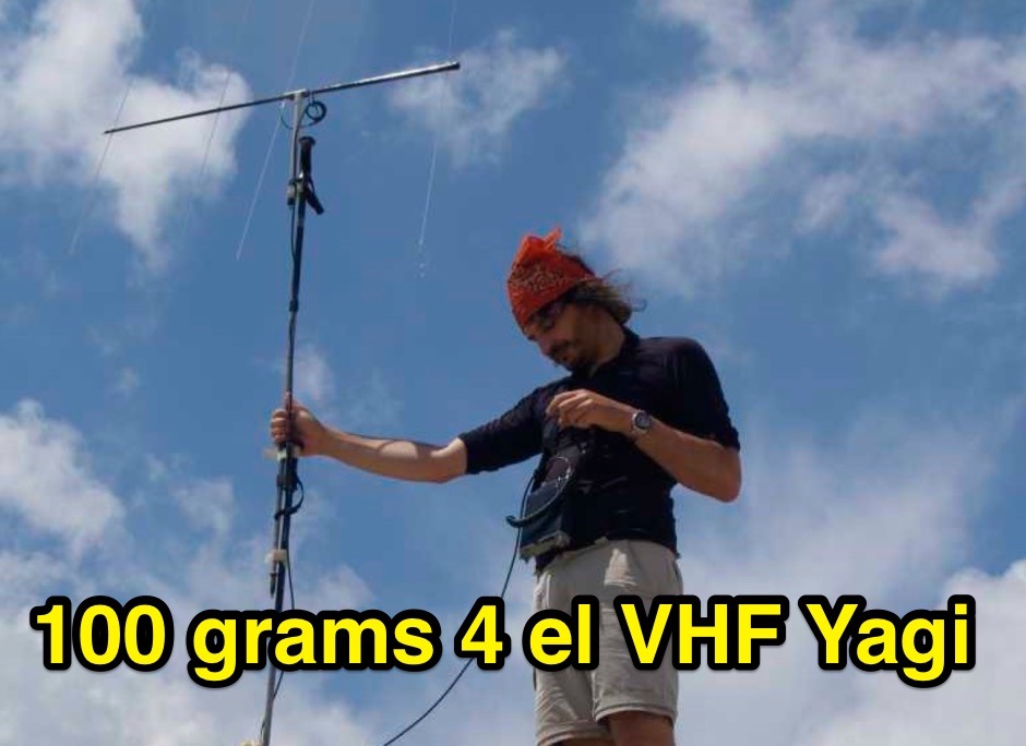 A portable VHF home-made Yagi-Uda antenna, that is extremely easy to build and very cheap. Moreover this antenna, while dismounted is just 1 meter long, and the total weight is just 100 grams.
 -
 A schematic design of the W3DZZ antenna in portugues with description of trap building
 -
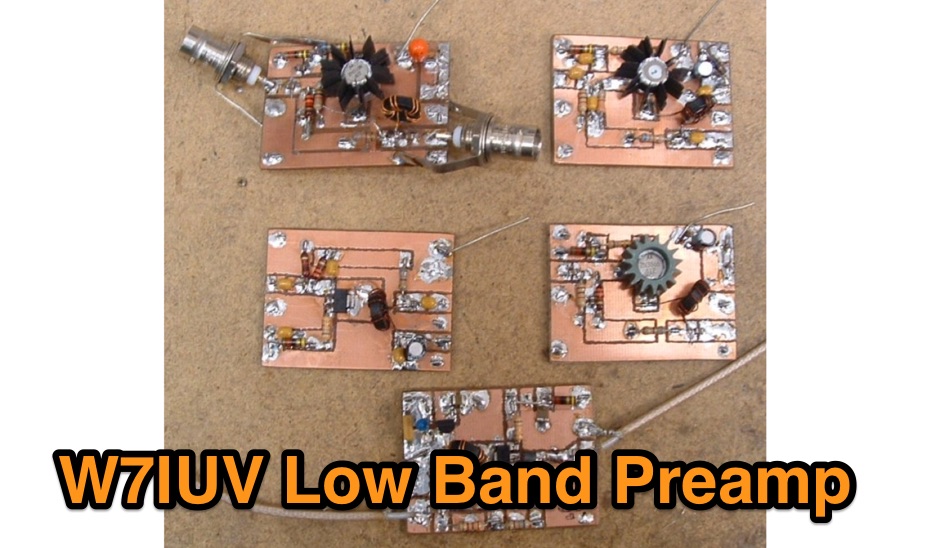 Pre amplifier using a 2N5109 for the 160 meters band
 -
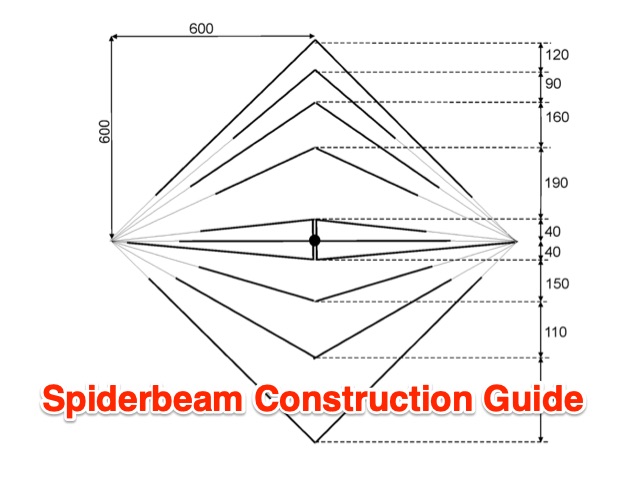 Build a spiderbeam from scratch for 20-17-15-12-10 meters band
 -
 This is a popular antenna design as the performance is very good across the HF bands and requires little or no tuning. It is a dipole fed off center with a 4:1 current balun at the offset feedpoint. The antenna shown covers 80, 40, 20 and 10 meters with 15 meters and WARC bands
 -
 A three-frequency multi-band dipole that can be extended easily to additional bands. This article includes a multiband fan-dipole antenna for 80-40-20-10 meter band.
 -
 The ZS6BKW wire antenna, a variant of the G5RV, utilizes a specific 13m (42.6 ft) length of 450-ohm window line as its matching section, feeding a 28.5m (93.5 ft) flat-top element. This design aims for lower SWR on 40m, 20m, 17m, 12m, and 10m compared to a standard G5RV, often achieving SWR values below 1.5:1 on these bands without an antenna tuner. The feedpoint impedance transformation provided by the window line allows for direct connection to 50-ohm coax on multiple bands. F4FHH's experience involved constructing the ZS6BKW and evaluating its performance against an _OCF dipole_ (Off-Center Fed) on various HF frequencies. The article includes observations on SWR readings and operational effectiveness, highlighting the ZS6BKW's suitability for multi-band operation. The antenna's overall length, including the flat-top and window line, is approximately **41.5 meters** (136 feet), making it a significant wire antenna for fixed station use. Comparative analysis with the OCF dipole provided practical insights into the ZS6BKW's advantages and limitations, particularly concerning bandwidth and tuner requirements.
 -
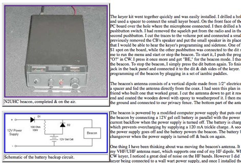 How to build a beacon keyer for 28 MHz using an old CB Radio transceiver, by Tom Sevart
 -
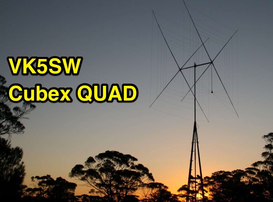 Pictures of a 2 element cubex Quad antenna at a height of 10 meter
 -
 CB Radio and 10 through 12 meter band radio dealer. Ranger Communications factory authorized dealer. Service 10 and 12 meter and CB radios.
 -
 Here is an antenna for the nineties. It's strong, computer designed, and has lots of gain. It is a full size, four element beam on 10, and three elements on 15 meters
 -
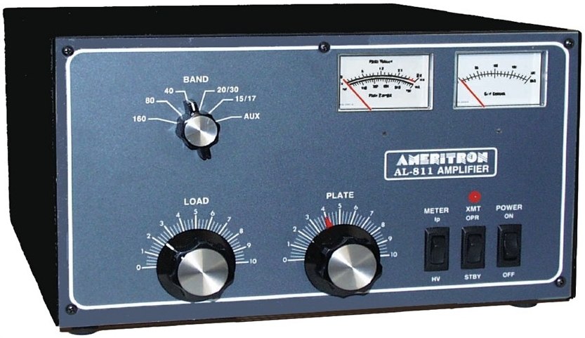 Are you experiencing very high SWR with the 10M Modification to Ameritron AL-811 amplifier ? This is a good forum topic to fix this problem.
 -
 VQLog 3.1 - 782 is a shareware logbook program designed for Windows operating systems (95, 98, NT, 2000, ME, XP, Vista, 7, 10, or later), supporting resolutions of 800x600 or higher. It can also operate on macOS and Linux via virtualization software like Virtual PC for MAC, Oracle VirtualBox, or VMware. The software facilitates QSO access by date, callsign, prefix, square, DXCC, and other parameters, offering robust import capabilities for ADIF, Cabrillo, and ASCII files from various contest and logbook programs. Key features include comprehensive award tracking for DXCC, WAZ, WAC, WPX, WAS, IOTA, TPEA, DIE, VUCC, 100EACW, and up to 30 user-defined awards. It generates customizable summaries and graphical statistics for QSO activity, DX contests, Most Wanted Squares (MWS), propagation openings, and prefixes. VQLog supports DX-Spot reception and processing from DX-Cluster and PSK-Reporter with programmable warnings, integrates with callbook services like QRZ.COM and Buckmaster's CD, and offers online lookup. Electronic QSL and log upload support extends to LoTW, eQSL.cc, Clublog, and DXMAPS, with real-time updates for online logs. The program provides extended QSO information for VHF-DXers, including separate TX/RX frequencies, start/end times, propagation modes, and specific entry fields for MS, EME, and Tropo. CAT support for rig control and interfaces with ARSWIN and PstRotator for azimuth/elevation control are also included.
 -
 A multiband wire antenna with a twinlead feedline that can be easily tuned in several bands, witha 33 ft per leg you can have a 40 to 10 meters band coverage
 -
 The RTTY Net is one of several Nets run by the 3905 Century Club. There are SSB Nets on 160, 75, and 40 Meters and CW Nets on 80 and 40 Meters
 -
 Operating a ZS6BKW antenna often involves understanding its lineage from the _G5RV_ design, with specific modifications by ZS6BKW to optimize performance on several bands. Through computational analysis and field measurements, the antenna's dimensions were refined to allow operation on 10, 12, 17, 20, and 40 meters without an antenna tuner. For 80, 30, and 15 meters, a tuner is necessary, though efficiency on 30 and 15 meters is noted as not particularly high. The physical configuration consists of two 13.755-meter radiating elements fed by a 12.20-meter section of 450-ohm ladder line. Tuning the antenna on the 20-meter band is critical, and any deviation in the ladder line's characteristic impedance necessitates recalculating the element lengths. The design is also referenced in the 12th edition of _Rothammel's Antennenbuch_, page 219. Proper common mode current suppression is crucial at the transition from ladder line to coaxial cable. This can be achieved with a common mode choke, such as several turns of coax wound into a coil or over a ferrite toroid like an Amidon T130. While a 1:1 balun is an option, it may introduce issues.
 -
 A vertical dipole for 10, 15, 20 and 40 meters made adapting two Hustler Model 6-BTV antennas by w6sdo
 -
 Yet another G5RV antenna plan to build a G5RV Antenna for 80 to 10 meters usage
 -
 A portable 4 elements quad antenna for 144 MHz, 9 to 10 DBd forward gain, 30 DB front-to-back ratio, and 33 DB front-to-side ratio
 -
 A _Topfkreis_ antenna, also known as a "bicycle pump" antenna, is presented as a simple vertical design for the 70 cm band. This variant of the J-pole antenna is notable for not requiring a ground plane, simplifying deployment. The construction details specify using aluminum tubing for the radiating element, with precise measurements for the quarter-wavelength outer tube (32 mm diameter) and the three-quarter wavelength inner sliding tubes (10 mm and 8 mm). Feeding is via a 50-ohm coaxial cable connected 90 mm from the base of the central tube. This design can achieve a gain of **4 to 6 dB** when properly tuned using the adjustable radiating element. The article details the fabrication of a critical aluminum washer, suggesting a method using a hole saw and a drill press as a lathe for precise adjustment. The illustrated example is specifically for the 70-centimeter band, and the author, Pop, clarifies construction points in the comments, including material choices and assembly techniques, ensuring a robust build for VHF/UHF operation.
 -
 A 90-foot vertical antenna constructed from **aluminum irrigation tubing** is detailed, focusing on its innovative raising and lowering mechanism. The resource describes a **45-foot ginpole** system, allowing a single operator to erect or lower the antenna in minutes. It covers the mechanical design, including the pivot base, insulated joints for the tubing sections, and guy wire attachment points. The antenna consists of two 30-foot sections of 4-inch tubing and one 30-foot section of 2-inch tubing, stacked with the smaller diameter at the top. The electrical design incorporates PVC "condulet" boxes at the 30-foot and 60-foot points, housing relays to change the effective height for multi-band operation on 160, 80, 40, and 30 meters. Ferrite rod inductive chokes are used for DC control and to tune out gap capacitance. The antenna is fed with 1000 feet of open wire line, connected to a matching transformer comprising stacked toroids and a coaxial/toroidal balun. Grounding is achieved with a 3x3 foot grid of 16-gauge tinned copper wires with soldered crossovers.
 -

-
 Operational testing of a 10.07-meter portable HF vertical antenna, constructed from telescoping aluminum tubing (36, 32, 22, 17 mm diameters), yielded SWR measurements below 1.5 across multiple bands. Initial trials on 14.150 MHz showed an SWR of 1.6, while 7.075 MHz was problematic. Subsequent adjustments, including a 13 cm extension to the radiating element, improved performance, enabling operation on 6, 15, and 40 meters without a balun, and adding 12 meters with a balun. The design prioritizes portability, allowing transport in a standard vehicle and single-person deployment. Four 10.07-meter radials are connected at the base to enhance ground plane effectiveness. The article details the mechanical assembly, including custom adapters for tube transitions and a PVC sanitary tube sleeve for base insulation, ensuring robust field deployment. Final SWR measurements, documented with an _MFJ-259_ antenna analyzer, confirm operational ranges: 6.800-7.500 MHz (SWR < 1.5), 20.800-22.500 MHz (SWR < 1.5), and 48.800-51.500 MHz (SWR < 1.5) without a balun. With a balun, the antenna achieved SWR < 1.5 on 13.750-15.000 MHz and 24.890-28.350 MHz, demonstrating its versatility for portable _DXpeditions_.
 -
 This antenna consists of 4 resonate dipoles made from 12 insulated copper electrical wire. The dipoles are resonate on the following bands: 6 meters, 10 meters, 12 meters and 17 meters.
 -

-
 Demonstrates the design and construction of a 9-element Yagi antenna for the **70 cm band** (432 MHz), based on the DK7ZB concept. The resource details EZNEC+ calculations for a single antenna, providing gain, sidelobe suppression, and front-to-back ratio figures. It also presents a comprehensive analysis of stacking two such antennas, including optimal stacking distance (1000 mm) and the resulting performance enhancements for the stacked array, such as an increased gain of 17.03 dBi. The article includes detailed drawings, wire file dimensions in millimeters, and azimuth/elevation plots for both single and stacked configurations. Practical construction steps are documented with original photographs, illustrating element mounting, the **28 Ohm matching system** using two quarter-wave 75 Ohm transmission lines, and the critical N-connector wiring. It also covers the iterative process of fine-tuning the driven element length to achieve a return loss of 20 dB, validating the EZNEC+ simulation results with actual measurements.
 -
 A project for a homemade multiband Hexbeam antenna for 10, 12, 15, 17 and 20 meters
 -
 A five element quad antenna for 144 MHz DIY Project. This 2 Meter 5 Element Quad antenna was modeled using EZNEC, with a boom from a UHF TV antenna and CPVC pipe for spreaders. Constructed for 146MHz, it exhibits a gain of 10.7dB and an impedance of 75 ohms. Real-world results surpass the HT antenna, reaching over 20 repeaters up to 75 miles away. The design, costing around $10, employs simple tools for assembly.
 -
 This low power transmitter is developed for ARDF exercising purposes but of course can be used as super QRP transmitter either. With 1 or 2 meter wire as antenna and a ARDF receiver with ferrite-rod antenna the range is about 100m but with better antennas and a 'real' receiver the range is probably much larger.
 -
 A simple 7 bands off-center dipole wire antenna designed to work on 80 meters band and that can cover also 40m 30m 20m 15m 12m 10m with acceptable SWR
 -
 Presents a construction project for a linear-loaded 40-meter rotatable dipole, detailing the design evolution from mid-element coils to 300-ohm twinlead loading. It covers material selection, including repurposed fishing poles and EMT conduit, and outlines the assembly process for the antenna elements and mounting plate. The resource provides specific measurements for element lengths and linear loading sections, along with SWR plots demonstrating the antenna's resonance at 7.035 MHz with a 1.1:1 SWR, and bandwidth up to 7.120 MHz below 2:1 SWR. The article documents the antenna's performance during various RTTY and CW contests, including the SARTG RTTY and SCC RTTY contests in August 2006, and the ARRL DX CW and CQWW WPX RTTY contests in February 2007. It reports successful operation at 500-1000W, noting improved performance after replacing a faulty coax cable. Specific DX contacts from British Columbia, including stations in Europe and South Africa, are listed, illustrating the antenna's capability despite its shortened length and relatively low height of 55 feet. The content highlights practical considerations such as weatherproofing the connections and supporting the fiberglass elements to prevent sagging. It also includes a brief comparison to an inverted-V at similar height and a ground-mounted vertical, noting the rotatable dipole's quieter reception. The author shares insights into the iterative design process and tuning adjustments made to achieve optimal resonance.
 -
 A 10 meters band Slim Jim antenna project, made with a 450 Ohm slotted ribbon cable and secured on a 8 m fishing pole, by Steve G0KYA
 -
 Constructing a portable, high-gain antenna for _AO-40_ satellite operations presents unique challenges, particularly regarding mechanical stability and parabolic accuracy. This resource details the build of a 1.2-meter "brolly dish" antenna, utilizing a non-conducting fiberglass umbrella frame as its foundation. The project outlines a method for achieving a parabolic shape using stressed aluminum fly screen mesh, guided by practical geometry and a temporary dowel template. Key steps include selecting an appropriate umbrella with a suitable f/D ratio (ideally >0.25), removing the original fabric, and precisely cutting and attaching eight segments of fly screen to the struts to form the reflective surface. The construction process, which took approximately five hours for the author, _G6LVB_, resulted in a dish with an f/D of 0.27 (depth=270mm, diameter=1160mm, f=310mm). The article also describes a modification to a _TransSystem AIDC_ feed, incorporating a PCB reflector behind the dipole for easier mounting. Performance tests at a squint angle of 15 deg and a range of 50,000km yielded a signal-to-noise ratio of 33dB on the S2 beacon and 23dB for SSB signals, indicating strong reception. The author notes that the modified umbrella may not close fully without risking surface disfigurement.
 -
 Compact and efficient magnetic loop antenna that cover from 40 to 10 meters project by G8ODE published by RSARS
 -

-
 Ten-Ten International Net, or 10-10 for short, is an organization of amateur radio operators dedicated to maintaining high levels of amateur radio communications on the 10-meter amateur band (28.0-29.7 MHz).
 -
 The Yaesu FT-100 is a miniature mobile transceiver that provides coverage of the 160 to 6 meter bands plus the 144 MHz and 430 MHz bands
 -
 The ZS6BKW antenna, a popular multiband wire antenna, offers improved band matching compared to the traditional G5RV. This construction guide details the process, beginning with specific dimensions: 13.11 meters (43 feet) for the 450-ohm ladder line and initial dipole arm lengths of approximately 14.8 meters each. It emphasizes the critical role of an _antenna analyzer_ for accurate tuning, particularly for determining the velocity factor of the ladder line and achieving a 1:1 impedance match. The article outlines the materials required, including a 1:1 current balun, 450-ohm window line, wire for the dipole arms, and a 50-ohm non-inductive resistor for testing. It provides a step-by-step procedure for cutting the ladder line to its electrical half-wavelength, explaining how to calculate the velocity factor using measured and free-space frequencies. For instance, a measured 50-ohm impedance at 12.54 MHz with a calculated free-space half-wavelength frequency of 11.44 MHz yields a velocity factor of 0.91. Final adjustments involve hoisting the antenna to its operational height and fine-tuning the dipole arm lengths to achieve optimal SWR, specifically targeting 14.200 MHz. The _ZS6BKW_ design is noted for its performance on 80m, 40m, 20m, 10m, and 6m, though it is not optimized for 15m operation. The author, _VK4MDX_, shares practical tips for durable construction using stainless steel wire and cable clamps.
 -
 The Vee Beam antenna project presents a versatile solution for hams, enabling operation across all eight High Frequency bands (80m to 10m) with significant gain on 20m to 10m. This easy-to-construct antenna utilizes two long wires at an angle, enhancing directional performance and minimizing ground losses. With a low visual profile, it is discreet and effective for various applications. The design allows for optimal leg lengths and included angles, ensuring robust performance while maintaining simplicity in construction and operation. The V Beam antenna is an aerial that you can use on all eight High Frequency amateur bands (80, 40, 30, 20, 17, 15, 12 and 10m) with an antenna tuner, and which gives significant gain on the five bands from 20 to 10 meters band.
 -
 This article presents a technical investigation into spurious emissions from the Yaesu FT-847 transceiver when operating on the 70MHz (4-meter) band. The author discovered significant problems with both factory "UK spec" and modified units. Spectrum analysis revealed that when transmitting at 70.2MHz, the radio produces numerous spurious signals, with the most prominent emission at 45.6MHz measuring only 3dB below the fundamental frequency. The study also documents poor power efficiency on 4m (10.3% at 30W output) compared to 6m operation (23.5% at 30W). Tests verified that jumper configurations had no effect on filter selection. The author warns that using these radios on 4m may violate license conditions due to excessive spurious emissions.
 -

-
 DK7ZB- Moxons with Aluminium Tubes, plans for moxon antenna for 6 10 12 15 meters
 -
-
 A 500-watt mobile antenna project details the conversion of an old 10m hamstick into a highly efficient, multiband "bugstick" for HF operation. The core modification involves replacing the original coil with 25 turns of 6 turns-per-inch, 1.5-inch diameter coil stock, fabricated from #14 wire. This design, intended for a 3-magnet mount on a vehicle cab, achieves resonance on multiple bands by shorting out specific turns on the coil, similar to a **bugcatcher** antenna. Measurements taken with an MFJ-259 analyzer on a GMC pickup show 0 turns shorted for 20 meters (14.2 MHz), 10 turns for 17 meters, 16 turns for 15 meters, 19 turns for 12 meters, and 23 turns for 10 meters. The construction emphasizes using UV-resistant tie-wraps and #14 solid wire with crimp lugs for robust RF connections, bypassing the fiberglass rod for current flow. A bonus section details a 40-meter version, utilizing 48 turns of 8 TPI, 2-inch diameter coil stock.
 -
 An end-fed halfwave antenna for 20 meters band with balun pictures and description by PD7MAA
 -
 An Off-center-feed antenna that covers 80, 40, 20, 17, 15, 12, 10, and 6 meters