Search results
Query: 100
Links: 448 | Categories: 13
Categories
- Radio Equipment > HF Amplifiers > Acom 1000
- Radio Equipment > VHF-UHF Mobile > ICOM IC-2100H
- Radio Equipment > HF Transceivers > Icom IC-7100
- Radio Equipment > HF Transceivers > Icom IC-9100
- Radio Equipment > Receivers > Icom IC-R7100
- Radio Equipment > Antenna Tuners > LDG Z-100
- Operating Modes > Satellites > QO-100
- Radio Equipment > HF Amplifiers > Yaesu FL-2100
- Radio Equipment > HF Transceivers > Yaesu FT-100
- Radio Equipment > HF Transceivers > Yaesu FT-1000MP
- Radio Equipment > Microphones > Yaesu MD-100
- Radio Equipment > Scanners > Radio Shack PRO-94
- Radio Equipment > HF Transceivers > Yaesu FT-891
-
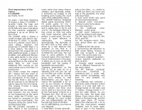
 Presents a QRP AM/CW transmitter project specifically designed for the 10-meter band, utilizing a crystal oscillator and a collector-modulated AM oscillator. The design employs a 2N2219(A) transistor in a Colpitts configuration, generating 100 to 350 mW of RF output power depending on the 9-18 Volt supply voltage and modulation depth. Frequency stability is maintained by a 28 MHz crystal, with fine-tuning possible via a Ct1 trimmer capacitor for approximately 1 kHz adjustment. The resource details the RF oscillator stage, implemented with a 2N2219 NPN transistor, emphasizing frequency stability and low power dissipation. It also covers the amplitude modulation stage, managed by a 2N2905 PNP transistor, which impresses audio information onto the carrier. Selective components (C3, C4, C7, C5) enhance voice frequencies within a +/- 5 kHz bandwidth, and modulation depth is controlled by R2 and R3. The project includes a 3-element L-type narrow bandpass filter (Ct3, L3, C10) to suppress harmonics and ensure a clean output signal. The project provides a complete schematic diagram, a comprehensive parts list including specific capacitor, resistor, and inductor values, and construction notes for the coils (L1, L2, L3). It also offers practical advice on enclosure requirements, suggesting an all-metal case or a PVC box with graphite paint for RF shielding. Operational parameters such as current draw (27mA@9V to 45mA@16V) and input impedance (50 Ohms) are specified, alongside guidance on antenna matching and the importance of a valid amateur radio license for 10-meter band operation.
 -
 The ZS6BKW multiband antenna, an optimized variant of the classic G5RV, features a 102-foot (31.1 m) horizontal span and a 39.1-foot ladder line matching section. This design, derived by G0GSF (formerly ZS6BKW) in the early 1980s using computer programs and _Smith charts_, aims for improved SWR across multiple HF bands compared to its predecessor. Construction details specify Wireman 554 ladder line and #14 AWG THHN copper wire for the radiators, with precise instructions for determining the velocity factor (VF) of the ladder line using an antenna analyzer or dip meter, ensuring accurate physical length for the matching section. The radiator length is electrically 1.35 wavelengths for the 20-meter band, requiring careful trimming during tuning. Field measurements with an _AIM-4170C_ analyzer by KI4PMI and NC4FB demonstrated good SWR curves and bandwidth on 6, 10, 12, 17, 20, and 40 meters. The antenna was deemed unusable on 15 and 30 meters due to very high SWR, but an LDG AT-100PRO autotuner successfully brought 6 and 80 meters into tune. Contacts were made on 80, 40, 20, and 17 meters, including a **17-meter** contact to Spain. EZNEC models for 80-6 meters are provided, along with an AutoEZ model by AC6LA, which predicted good SWR for 80-10 meters. W5DXP's modifications for an all-band HF ZS6BKW are also referenced.
 -
 Organized in 1939, YLRL (Young Ladies Radio League) is a nonprofit organization of women Amateur Radio Licensees. With a membership of approximately 800, it is international in scope with about 100 of those members who are DX YLs.
 -
 A magnetic loop antenna working from 30 to 15 meters with 100W
 -
-
 Demonstrates how to construct an automatic band decoder, moving beyond manual selector switches for antenna and filter control. It addresses the challenge of varying band data outputs from different transceivers: Icom rigs provide voltage values, Yaesu rigs use Binary Coded Decimal (BCD), and Kenwood rigs lack direct band data output. The resource highlights a clever solution utilizing logging software like _CT (K1EA)_ and _DX4WIN_ to emulate Yaesu's BCD output via a PC's printer port, making the decoder compatible with any rig. The author details experiences building decoders based on designs by Bob _K6XX_ and Guy _ON4AOI_, noting K6XX's simple TTL chip design and ON4AOI's more comprehensive, opto-isolated unit capable of controlling ten outputs and bandpass filters like the _Dunestar_. It also references a _W9XT_ board design, which Steve Wilson, G3VMW, modified with BD140 transistors for source drivers, emphasizing safety. The author successfully cased an ON4AOI-based decoder in an old modem case, connecting it to an FT1000MP or a PC printer port to drive remote relays and a Dunestar Band Pass Filter.
 -
 Common problems and improper operations of Yaesu FL 2100 RF power amplifier
 -
 This project details the construction of a **full-sized 40-meter vertical antenna**, born from a renewed interest in 7 MHz operation and a desire for improved effectiveness over simple dipoles. The author, K5DKZ, initially focused on VHF experimentation, which provided an inventory of aluminum tubing and fiberglass spreaders for this endeavor. Before this vertical, K5DKZ utilized an 80/40 meter inverted-vee trap dipole and a 40-meter broadband dipole, but now primarily uses a pair of full-sized, phased, quarter-wave verticals spaced 35 feet apart for serious 40-meter work. The construction involves a base-heavy design for stability, using a 44.5-inch section of 1-1/4 inch steel TV mast driven into 1-3/8 inch aluminum tubing, insulated by a 105-inch section of Schedule 40 PVC pipe. The assembly reaches 31 feet, close to the 32 feet required for a quarter-wavelength on 40 meters, with fine-tuning achieved by winding wire onto a fiberglass spreader. The design is explicitly presented as a foundation for a two-element 40-meter Yagi beam, outlining modifications like substituting aluminum for steel in the base and using an inductive hairpin match for the driven element. The article also discusses tuning considerations for a large 40-meter beam, noting the 100 to 200 kHz upward frequency shift when raised, and suggesting methods for installation on a tower. The author emphasizes the cost-effectiveness and good performance of the monopole approach, especially when multiple verticals are needed.
 -
 FT100: the yaesu ft-100 yahoo group
 -
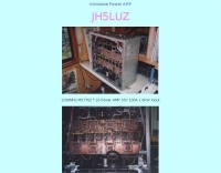 1296MHz M57762 * 16 Power AMP 16V 100A 1.6KW Input
 -
 A fractional bandwidth of up to 30:1 characterizes spiral antennas, making them highly effective across a very wide frequency range, often from 1 GHz to 30 GHz. The resource details two primary types: the **Log-Periodic Spiral Antenna** and the **Archimedean Spiral Antenna**, defining each with specific polar functions and illustrating their planar configurations. It explains that spiral antennas are typically circularly polarized, with a Half-Power Beamwidth (HPBW) of approximately 70-90 degrees, and a peak radiation direction perpendicular to the spiral plane. The content elaborates on critical design parameters affecting radiation, including the total length (outer radius) for lowest frequency, the flare rate ('a' constant) for optimal radiation versus capacitive behavior, the feed structure (often an infinite balun) for high-frequency operation, and the number of turns (typically 1.5 to 3 turns). It also discusses the theoretical impedance of 188 Ohms for Log-Periodic spirals, derived from Babinet's Principle, noting actual impedances are often 100-150 Ohms. The article presents a simple construction method for an Archimedean spiral, demonstrating VSWR and efficiency measurements. Measurements from a constructed spiral antenna show a VSWR that is fairly constant across the band, albeit with a mismatch loss of about 3 dB. The antenna efficiency remains around -5 dB (31.6%) across its operating range, indicating a decent wideband radiator despite opportunities for optimization.
 -
 This document details the design and construction of the PA70H, a 50-watt RF amplifier for the 70MHz (4-meter) amateur radio band. Built around the Mitsubishi RD70HVF1 MOSFET transistor, the amplifier delivers 45-55W output with 3-5W input power while operating on 13.8V DC at approximately 7-8A. The PCB design incorporates multiple protection circuits including overcurrent, SWR, and temperature control. The amplifier features various control modes including GND PTT, +13.8V PTT, and RF VOX. Two versions are available: PA70HLI (requiring 100mW input with additional driver) and PA70H (for 3-5W input). The comprehensive documentation includes circuit diagrams, assembly instructions, and performance data showing successful operation from both 100mW and 3.5W input sources.
 -
 This article loaded with nice pictures and schematics, describes a 160-10 meter linear amplifier that uses a pair of 3-500Z triode power tubes. It was designed and constructed by William Moneysmith, W4NFR. The amplifier features fast warm up and 1500-Watt RF output with 100-Watts of drive.
 -
 Receiver tests of some transceivers and receivers including FT-1000, FT-2000, IC-751, IC-756 IC-7800 and TS-870
 -
 Examines the Icom IC-2100H 2-meter mobile transceiver, detailing its operational characteristics and user experience. The review highlights the clear, easy-to-read display with internal labels, the button-filled microphone's functionality, and the rig's physical construction, including its weighty heat-sink and lack of a cooling fan. It also discusses memory programming, the unique amber-to-green backlight color options, and the radio's performance against _intermodulation_ in urban environments, noting it performs "pretty darn good" compared to other rigs. The analysis delves into a significant low-voltage cutoff problem, where the microphone ceases to function below approximately **12.6 VDC**, rendering the radio receive-only or causing it to stick in transmit. The author describes testing the voltage cutoff, observing it fluctuate from _12.38 VDC_ to 12.69 VDC. An update from Icom involved a "factory update" to the CPU's control code, which is strongly recommended for early-serial number units to prevent operational failure in low-power emergency scenarios.
 -
 The Yaesu FT-1000MP Mark-V, introduced at Dayton 2000 Hamvention, features a higher RF power of **200 W PEP** and a Class-A amplification SSB mode at 75 W. Key enhancements include an _Interlocked Digital/Analog Bandwidth Tracking system (IDBT)_, a Variable Front-End Filter (VRF) preselector, and improved ergonomics, notably a multi-function shuttle jog dial. This model, a successor to the 1996 FT-1000 and FT-1000MP, was designed to compete with high-end transceivers, despite its retail price of $4200 initially. The transceiver's physical dimensions are 406 x 135 x 348 mm (16 x 5.3 x 13.7 inches) with a weight of 14 kg (31 lbs), making it substantial. Its rear panel offers over 20 connections, including power, external DSP speaker, BAND DATA I/O, ALC, and multiple interface jacks for DVS-2, Packet, and RTTY. The unit also provides two keyer inputs, a DB9M serial interface for CAT, and two PL female antenna connectors, plus additional receive antenna jacks. Despite its advanced internal architecture, including two independent receivers with their own IF filters and AGC loops, the display technology, utilizing fluorescent discharge rather than LCD, contributes to an older aesthetic. The control panel is extensive, featuring 92 knobs and buttons, alongside numerous LED indicators for various modes and functions.
 -
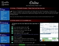 Online is a VT100/ANSI terminal emulator and Telnet client for Palm OS organizers. Connect to Unix systems, configure routers and reprogram embedded computers.
 -
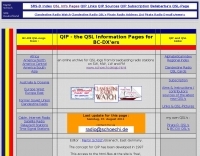 QSL Information Pages QIP for BC-DXers - more than 50000 qsl logs from more than 10000 BC-DX radio stations
 -

-

-
 The X80 multi-band HF vertical antenna, a commercial iteration of the Rybakov design, exhibits a physical length of 5.5 meters, or approximately 18 feet, and is constructed from aluminum tubing. It operates as a non-resonant vertical, requiring an external antenna tuner for impedance matching across its intended operating frequencies. The antenna's design incorporates a 1:4 UNUN at its base, facilitating a nominal 50-ohm feed point impedance for the coaxial cable. Performance observations indicate effective operation on 40 meters, 20 meters, 15 meters, and 10 meters, with reduced efficiency on 80 meters and 160 meters due to its relatively short electrical length for these lower bands. Comparative analysis with a G5RV dipole and a half-wave end-fed antenna reveals the X80 offers a lower take-off angle, beneficial for DX contacts, particularly on the higher HF bands. Field tests conducted with an Icom IC-706MKIIG transceiver and an LDG AT-100ProII autotuner demonstrate the X80's ability to achieve acceptable SWR across 80m through 10m. The antenna's compact footprint and ease of deployment make it suitable for restricted spaces or portable operations, though its performance on 80 meters is noted as a compromise compared to full-size resonant antennas.
 -
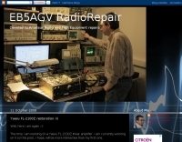 Repairing and restoring a Yaesu FL-2100Z amplifier
 -
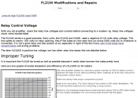
 The Yaesu FL2100Z is a HF linear amplifier rated for 1200W PEP input, and using two 572B triode tubes. This article explores the recommended operating conditions, and alternatives.
 -
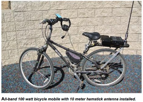 A bycicle ham radio station setup, with full band coverage
 -
 based on an FT-1000MP Reflector discussion with Bill Heinzinger, W9OL, 15/16 November 2002
 -
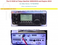 Firsts pictures of Icom IC-9100 taken at Tokyo HamFair 2009
 -
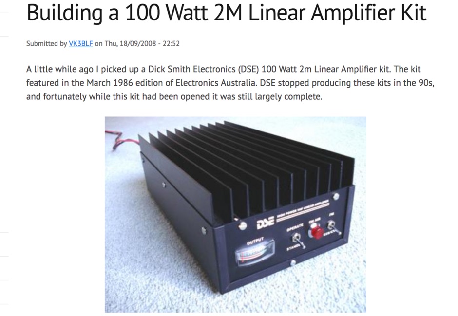 Article about assembling of a Dick Smith Electronics (DSE) 100 Watt VHF Linear Amplifier kit.
 -
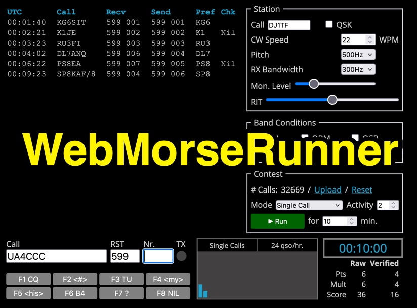 Web Morse Runne is an online CW (Morse code) contest simulator developed by DJ1TF - Thomas Fritzsche. This tool allows users to practice their Morse code receiving and sending skills in a simulated contest environment. Key configurable parameters include CW speed, with options ranging from 300Hz to 900Hz, and RX bandwidth, adjustable from 100Hz to 600Hz. Users can also set a monitor level and simulate various band conditions. The interface includes counters for calls and QSOs per hour, along with a timer. Pre-defined function keys are available for common contest exchanges such as F1 (CQ), F3 (TU), F6 (B4), F7 (?), and F8 (NIL). The simulator is designed for ham radio operators looking to improve their CW contesting proficiency.
 -
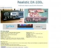 Modifications and improveents for the realistic DX-100L HF receiver by ON6MU
 -
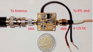 low-noise amplifier for HF reception, amplifies signals 80 to 100 times between 0.15 MHz and 30 MHz. It will let you hear more signals with your RTL-SDR plus Ham-It-Up setup
 -

-
 Over 100 amateur radio beacon audio files are presented, offering a direct auditory experience of propagation conditions across a wide spectrum of frequencies, from 1.8 MHz to 47 GHz. These recordings, primarily captured by IW3FZQ and IK3NWX, document signals from beacons such as DK0WCY, IY4M, GB3RAL, and S55ZRS, providing a valuable resource for **propagation study** and **beacon monitoring**. Each entry in the list specifies the beacon's callsign, its operating frequency in kHz, and the recording operator. This compilation includes signals from beacons located in various grid squares like JN55VF, JO44VQ, and IO91IN, illustrating diverse geographical origins. The frequencies covered span the 160m, 80m, 40m, 30m, 20m, 17m, 15m, 12m, 10m, 6m, 4m, 2m, 70cm, 23cm, 6cm, 3cm, 1.2cm, and 6mm amateur bands. Users can listen to these recordings to identify characteristic beacon tones and observe signal strength variations. The resource also invites other radio amateurs to contribute their own beacon audio files, fostering a collaborative archive of propagation data. The last update to this collection was on March 24, 2009, indicating a historical snapshot of beacon activity. Accessing the files requires the Real Player software.
 -
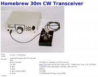 10.100 - 10.140 MHz 3 Watts output by 7n3wvm
 -
 A system designed to automatically tune small transmitting magnetic loop antennas, particularly beneficial for **contest operations** where rapid frequency changes are common. The core of the system involves a PC-based control application, AutoCap, written in C#, which monitors antenna SWR via an external meter and commands a motor interface to adjust the loop's variable capacitor. The software is compatible with Windows and Linux via the Mono framework, offering a graphical user interface for monitoring system status, SWR, power, and motor commands. Key components include one or more magnetic loop antennas equipped with DC or stepper motors for capacitor adjustment, an SWR meter with data output (such as the Telepost LP-100A or a homebrew serial/USB SWR meter), the AutoCap PC software, and a motor interface. The most effective motor interface utilizes an **Arduino-based controller** with custom firmware, providing precise control over both simple DC motors and stepper motors, and supporting features like motor braking for finer adjustments. The system allows for configurable SWR thresholds, pulse widths, and motor effort settings to optimize tuning speed and resolution. Optional radio integration provides frequency hints, enabling the algorithm to learn the relationship between motor actions and resonant frequency, thereby speeding up initial tuning responses. The software also supports antenna profiles, allowing operators to save and recall specific configurations for different loops, including accumulated frequency hint data.
 -
 This is a one for all antenna tuner with wide range tuning on all the HF bands. The tuner is based on a G3WQW design. DIY project by PD7MAA
 -
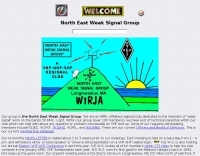 The North East Weak Signal Group (N.E.W.S.) website serves as the digital hub for an ARRL-affiliated regional club dedicated to _weak signal_ work across the VHF, UHF, and SHF spectrum, from 50 MHz up to light. It provides essential information for members and prospective enthusiasts, including the club's constitution and by-laws, details on officers and the board of directors, and a calendar of meetings and events. The site also features an application for membership, information on dues, and a membership roster, fostering a sense of community among its over 100 members. A significant feature of the site is its extensive archive of conference papers, including proceedings from the _Eastern VHF/UHF/Microwave Conference_ dating back to 2009. These papers cover a wide array of technical topics relevant to weak signal operations. The site also lists _50 MHz Beacons_ and _144 MHz and up Beacons_, along with links to other VHF and above resources, providing practical tools and knowledge for operators interested in pushing the boundaries of amateur radio communication.
 -
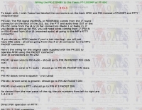 Wiring the PK-232MBX to the Yaesu FT-1000MP or FT-990
 -
 How to homemade a multi-band HF dipole using 100 meter of speaker wire, 2 strandsm including a homebrew 1:1 choke balun
 -
 Linear Amp UK specializes in the design and production of high-quality linear amplifiers, offering models for HF, VHF, and UHF amateur and commercial applications. The company emphasizes nearly 30 years of experience in crafting each unit, ensuring robust performance and longevity. Their product line includes amplifiers engineered for a 100% duty cycle, promoting continuous and reliable operation across various modes. The amplifiers feature solid, dependable designs, ensuring quiet and effortless performance during transmission. Each unit is hand-built to stringent standards, reflecting a commitment to durability and operational stability. All products are CE approved, confirming compliance with European safety and environmental directives, and come with a standard two-year warranty, providing assurance to operators. Key specifications often include coverage for 1.8-30MHz (WARC bands), 50MHz, 70MHz, and 144MHz, utilizing tubes such as 811, 572, 811A, 572B, GS35, GS35B, 8877, 3CX1500, and _3CX1500A7_ in their designs.
 -
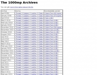 Archive of yaesu ft-1000MP digests since january 2001
 -
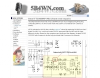 How to repair a FT1000MP front end, damaged from too much neighbouring RF during contesting
 -
 A page dedicated to Yaesu FL-2100Z linear amplifier for amateur hf bands
 -
 Technical resource and information on improving ft1000 receiver performance
 -
 **LDG Z100** automatic tuner repair focuses on toroid replacement and troubleshooting. The guide provides detailed steps for diagnosing and fixing common issues with the toroid, which is crucial for the tuner's performance. It includes specific instructions on disassembling the unit, identifying faulty components, and sourcing replacements. The document is technical, requiring familiarity with electronic components and soldering techniques. It emphasizes the importance of using the correct toroid specifications to ensure optimal functionality. Successful repair of the **LDG Z100** ATU restores its ability to match a wide range of antennas, enhancing transmission efficiency. The guide compares the performance before and after the repair, highlighting improvements in SWR readings and overall reliability. Practical application of this repair extends the life of the tuner, making it a cost-effective solution for amateur radio operators. The document serves as a reference for similar repairs on other models, providing insights into common issues and solutions. It is a valuable resource for those looking to maintain their equipment without resorting to professional services.
 -
 A Portable 100 watt radio station setup composed by a 706MKII transceiver, Z-100 antenna tuner and power supply by N1GY
 -
 The K-Com website, originally intended for RFI rejection products, currently hosts content for a Nigerian football betting platform. The site promotes wagering on live EPL, NPFL, and UCL matches, offering competitive odds and instant OPay and bank payouts. It highlights features such as a **99 sign-up bonus** for new players, daily deposit rewards, and VIP cashback, alongside a mobile-friendly interface and NLRC licensing. The platform provides a demo hall with _1,000,000 demo credits_ for guest players to test strategies without registration. It emphasizes secure and reliable gameplay, instant withdrawals, and multi-game access, claiming over 100,000 active players. The content includes user testimonials and an FAQ section addressing game access, registration, promotions, and mobile compatibility, but contains no information related to amateur radio or RFI filters.
 -
-
 YAESU FT-1000MP Mark V ESSB Modifications pdf file
 -
 A 200 kHz bandwidth digital transmission system for image transfer in the Amateur Service is under development, specifically targeting VHF allocations. John B. Stephensen, KD6OZH, leads this project under an FCC Special Temporary Authority (STA) valid until September 10, 2006, authorizing emissions up to 200 kHz bandwidth in the 50.3-50.8 MHz segment. Current regulations typically limit bandwidths to 20 kHz on VHF amateur bands, making this STA crucial for testing wideband digital modes. The modem, a modified **OFDM** (Orthogonal Frequency Division Multiplexed) unit, was initially tested on the 70-cm band. It splits a high-rate data stream into multiple low-rate subcarriers to mitigate multipath echoes. The system uses a DCP-1 card with a Xilinx XC3S400 FPGA and Oki Semiconductor ML67Q5003 microcontroller. The transmitter, located at 36d 46m 30s N, 119d 46m 22s W, generates 150 WPEP into an 8 dBi gain vertical antenna, while the mobile receiver uses a Ham-stick. Three data formats for 50, 100, and 200 kHz channels are being tested, with encoded data rates of 96, 192, and 384 kbps. Verilog code for the VHF OFDM modem is 95% simulated, with modifications from the UHF version including increased filter coefficient precision and a change from Ungerboeck **TCM** to BICM for improved performance over fading paths. Final tests will involve one-way over-the-air measurements of bit error rates and coverage area.