Search results
Query: 40m
Links: 238 | Categories: 2
Categories
-
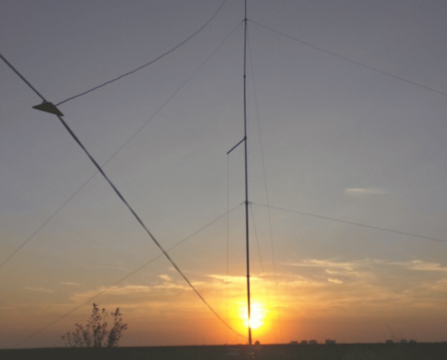
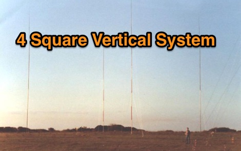 This page is a short description of the four phased verticals system for 160m 80m and 40m
 -
-
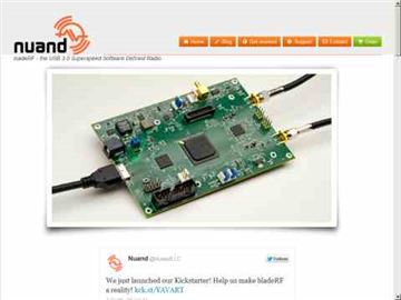 Nuand id the maker of bladeRF - the USB 3.0 Superspeed Software Defined Radio, 300MHz - 3.8GHz RF frequency range Independent RX/TX 12-bit 40MSPS quadrature sampling
 -
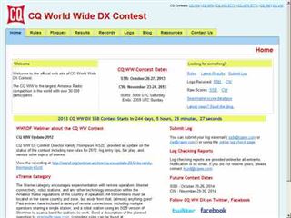 The CQ World Wide DX Contest records page details the highest scores achieved in the CQ WW DX Contest across various categories and years. It systematically lists records for both SSB and CW modes, segmenting results by entry class such as Multi-Multi, Multi-Two, Multi-Single High, Multi-Single Low, Single Operator High Power, Single Operator Low Power, Single Operator QRP, Single Operator Assisted High, Single Operator Assisted Low, and Single Operator Assisted QRP. Each record entry specifies the callsign, the operator's callsign in parentheses if different, the year of operation, and the total score achieved. The data is further broken down by individual amateur radio bands, including 160m, 80m, 40m, 20m, 15m, and 10m, allowing for granular analysis of performance within specific frequency segments. The page also includes records for the "ALL" band category, representing cumulative scores across all operational bands. The presented records span from 1948 to 2025, providing a historical perspective on contest performance. This resource also references other CQ contests like CQ WPX, CQ WW RTTY, CQ WPX RTTY, CQ 160, CQ VHF, and WW DIGI, indicating a broader context of contest record keeping. It explicitly states that late logs are not included in the records, ensuring data integrity. The page is maintained by the World Wide Radio Operators Foundation, Inc.
 -
 The WB5RVZ Genesis Radio G40 build log documents the construction of a 5W QRP 40m SDR transceiver kit, detailing each phase of assembly from power supply to RF filtering. It provides specific component lists, parts placement diagrams, and testing procedures for stages like the local oscillator, Tayloe detector, and RX op-amps. The resource highlights discrepancies between documentation versions and offers practical advice for builders, including a "virtual build" approach to preemptively address potential ambiguities in component identification and placement. It also addresses a specific "VK6IC Fix" for early board revisions, involving trace cuts and jumper wires for improved performance. The build log presents measured voltages and expected current consumption for various stages, such as the 4.9-5.0 Vdc on the 5V rail and under 100mA for RX current. It outlines critical adjustments like image rejection tuning, a common procedure for direct conversion receivers. The resource also includes practical tips for handling components like the 2N3866 transistor and its heatsink, emphasizing pre-assembly. It details the winding of two 1.45 uH toroidal inductors on T50-6 cores with 17 turns of #20 AWG wire, crucial for the RF path.
 -
 A simple dipole for 40m band feeded with 450-Ohm openwire feedline includes MMANA Gal files to download
 -
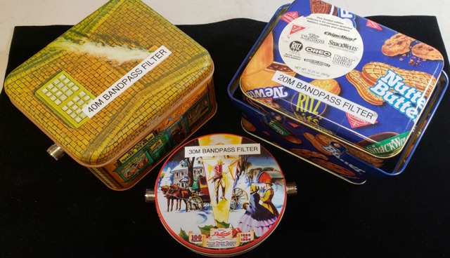 Homemade LC Bandpass Filters for 20M, 30M, 40M In multi-station environments like special events, field day, portable operating, is very important to protect receivers from excessively strong signals. Bandpass filters help to protect your transceivers.
 -
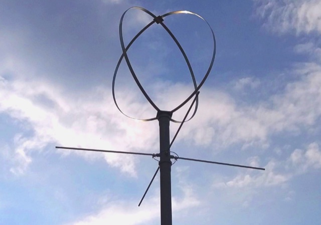
 Isotron antennas are antennas of reduced size, without tuning. On 40 and 80m band, it is made of two plates into v whose angles are connected by a coil. In this article the description of a home made realization for the 40m band.
 -
 A monoband delta loop antenna for the 7 MHz. This vertically polarized DX Antenna is a full wavelength sngle side antenna and has a total length of 42.3 meters (137,1 inch) Can be easily setup with a flag pole or fishing pole as center top mast. For optimal performance lower side should be at 2 meter above the ground. This antenna offers a low radiation angle and 1 DB Gain.
 -
 A dual band dipole antenna for 40 and 80 meters band. Total lenght of 26 meters, foreseen two coils at aprox 11 meters distance from center feed.
 -
 The CQ World Wide DX Contest records document top scores, with the Multi-Multi SSB category showing CN8WW achieving **78,170,508 points** in 2000. These records span from 1948 to 2025, categorizing results by region, operating class (e.g., Single Operator High Power, Low Power, QRP, Assisted), and specific bands like 10M, 15M, 20M, 40M, 80M, and 160M. For instance, EF8R (E77DX) holds the All-Band High Power SSB record with **25,747,775 points** in 2025. Each entry includes the callsign (with operator callsign in parentheses for guest ops), year of operation, and total score. The _CQ WW DX Contest_ also features records for the RTTY and VHF contests, alongside the main SSB and CW categories. QRP records demonstrate significant achievements, such as P40W (W2GD) with 5,097,780 points in the All-Band SSB QRP category in 2000. Multi-Two and Multi-Single categories are also detailed, providing a comprehensive overview of competitive performance.
 -
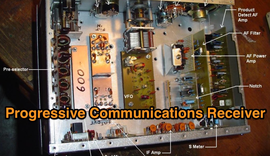 The purpose of this webpage is to document an attempt at this project starting with the 80m core receiver first and also having the parts on hand for then adding the first dual conversion band (40m)
 -
 Documents the OC1I and OC6I IOTA DXpeditions to Peru, specifically highlighting operations from SA-098 (Isla La Leona) and SA-076 (Isla Lobos de Afuera). The OC1I team logged over **8000 QSOs** from SA-076, while OC6I made 1400 QSOs from SA-098, despite challenging propagation conditions. The resource details the equipment used, including an _IC-7000_, an IC-706mkIIG, and a TS-440SAT, along with various antennas such as a 160m dipole, FD4, G5RV, and a multi-band vertical for 17m, 20m, 30m, and 40m. The DXpedition dates are specified: OC6I operated from SA-098 between December 28 and December 30, while OC1I was active from SA-076 from January 2 to January 7. Both operations are confirmed as valid for IOTA credit. The page also includes a video link for the OC6I operation and a photo gallery from the DXpedition. Feedback is welcomed, and the webmaster is identified as Bodo Fritsche, DL3OCH.
 -
 A portable (15.5 foot diameter) NVIS loop for 3.5 to 7.3 MHz. Performs well at high and low takeoff angles, and has smaller footprint than most NVIS antennas.
 -
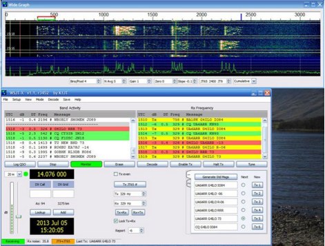 A guide to setup and operate on JT-9 mode, including a sample QSO and setup hints by VA3PAW
 -
 No exotic claims are made for this antenna. Author just tried a few WSPR experiments on 40 meters and was surprised with the results. What appears below may inspire you to try something equally off-the-wall, to see what happens.
 -
 Designing and constructing a two-element receiving loop antenna array for HF operation involves specific considerations for achieving high directivity and noise reduction. This resource details a homebrew system comprising two 30-inch diamond-shaped loops, spaced 20 feet apart, which are fed through mast-mounted preamplifiers and passive signal combiners. The operational principle relies on adjusting phase delays between elements via precise _Belden 8241_ coaxial cable lengths, optimized for specific bands from 160m to 20m. Performance data, derived from _EZ-NEC_ modeling, illustrates consistent 90° azimuth-plane beamwidth and low take-off angles across the target bands, with _Receiving Directivity Factor_ (RDF) values comparable to a 300-foot Beverage antenna. The article presents detailed elevation and azimuth plots for 20m, 30m, 40m, 80m, and 160m, demonstrating the array's ability to provide strong response at low DX angles while also supporting _NVIS_ signals. Key components like the _DX Engineering RPA-1_ preamplifier and _DXE RSC-2_ signal combiner are discussed, alongside the importance of impedance matching to preserve antenna patterns. The construction emphasizes self-contained elements that do not require ground radials, offering a compact solution suitable for suburban environments and stealth installations, with a focus on optimizing receive performance independently from transmit antennas.
 -
 A modified Hairpin antenna for a wider bandwidth an mounted on a grounded metalic mast
 -
 This antenna is an off-center fed spiral dipole for 40 meters. The spiral dipole is very compact, making it well-suited for limited space (like an apartment patio), while the off-center feed gives the antenna some multiband capability.
 -
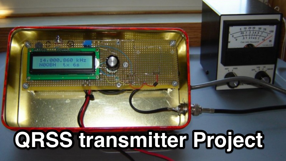 The N0QBH QRSS project page, a couple of projects using available kits for improved frequency and timing stability. A configurable DDS VFO 100mW transmitter with LCD display and a modified Hans Sommers 40m 100mW transmitter
 -
 Constructing an End-Fed Half-Wave (EFHW) antenna offers a practical solution for HF operators seeking a multiband wire antenna without the need for extensive radial systems. This design typically employs a high-impedance transformer at the feed point, matching the antenna's inherent high impedance to a 50-ohm coaxial feedline. The article specifically details a 2012 approach, focusing on a transformer with a 49:1 turns ratio, which is a common configuration for EFHW antennas. The resource outlines the construction of a wire element cut for a half-wavelength on the lowest desired band, with specific coil arrangements enabling operation on harmonically related bands such as 40m, 20m, and 10m. It discusses the physical dimensions and winding details for the matching transformer, often utilizing a ferrite toroid core to achieve the necessary impedance transformation. The content provides insights into the operational principles and practical considerations for deploying such an antenna, including methods for tuning and optimizing performance across multiple amateur radio bands. While acknowledging that the presented information from 2012 may be superseded by newer insights, it serves as a foundational reference for understanding EFHW antenna theory and construction.
 -
 An experimento of a 40 meter delta loop antenna both in horizontal and vertical polarization and several elevation angles with interesting notes about the effect of the radial field under the antenna.
 -
 DL1OFC, operating from Hankensbüttel, Germany, shares insights into the fascinating hobby of amateur radio. While the station has been on hiatus since 2016, the site provides a valuable archive of activities and technical information. DL1OFC was active across various bands and modes, including 145.225 MHz FM, 430.225 MHz FM, 29.600 MHz FM, and DMR via DB0AGM on TS-1 TG-262 DL. Shortwave operations included SSB on the 40m through 10m bands, as well as 6m. The site details regional amateur radio activities in and around Hankensbüttel, offering a glimpse into local field days and community involvement. A notable feature is Die Isetalrunde, a regional amateur radio net covering the area from the Harz mountains to the sea. The site also includes general information on radio technology, tips for obtaining an amateur radio license, and discussions on VHF/HF propagation, including specifics on the 70 MHz band.
 -
 A multi-band off centre fed dipole, designed to operate on all bands from 40m (7MHz) to 6m (50MHz). Author claims it will operate on 40, 30, 20, 17, 15, 12 and 10m without an ATU (SWR <3:1) plus 6m with an ATU.
 -
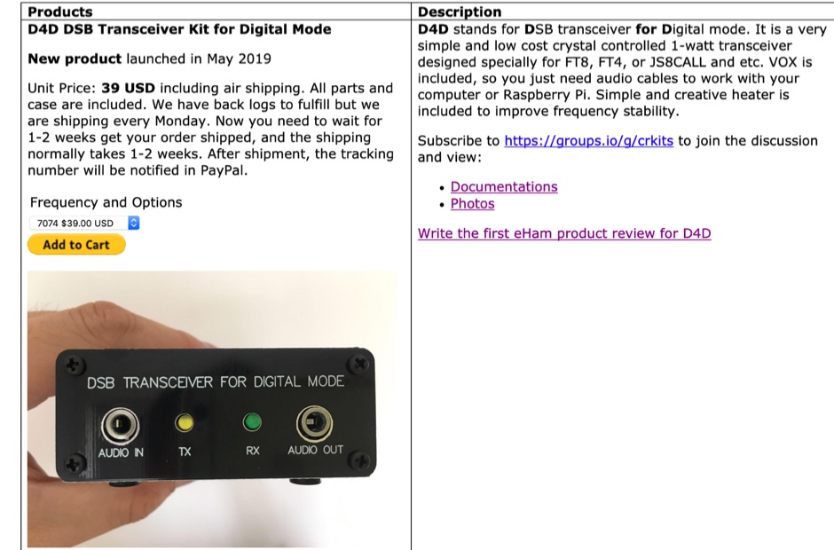 Since 2011, crkits offer radio kits that you cannot find on eBay or AliExpress. Includes HT-1A 20/40m Dual Band CW Transceiver Kit, D4D DSB Transceiver Kit for Digital Mode, R3500D ARDF Receiver, CW Transceiver Kit
 -
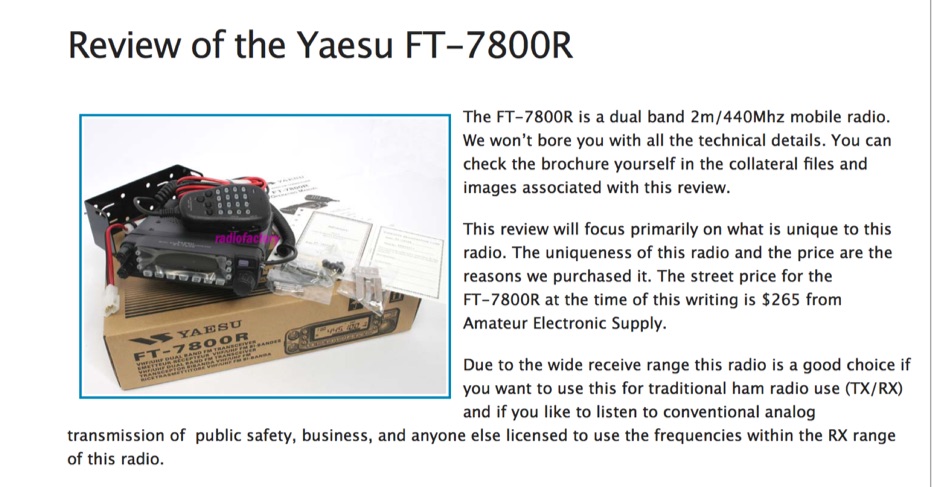 Yaesu FT-7800R dual band 2m/440Mhz mobile radio review
 -
 This project is a full wavelength, horizontal, loop antenna for the 40 metre Amateur Radio band, built using insulated copper wire in a diamond shape, supported by egg insulators, tethered to 4 masts, each 6.5m high
 -
 This page describes a comparison study on seven different beam antennas for 40 meters band. Yagi antennas, moxon antennas, mini horse all antennas are described with schema diagram , azimuth plot and SWR F/B Gain diagram
 -
 An 20 30 40 meters trapped dipole antenna plan for sota and portable operations.
 -
 Author experiments end fed half wave antennas using common two conductore speaker wire, this article features a couple of end-fed halfwave wires for the 40M and 20M bands.
 -
 A quarter wave vertical omni-directional antenna for 7 MHz. Formulas for dimensions in feet and meters are provided. Ideal radial angle is between 35° and 45°. Velocity factor (Vf) varies based on coax type.
 -
 No matching adjustments needed. Directly perfect match to 50 Ohms using a remotely switched wideband transformer
 -
 When operating contest in a multi transceiver environment interferences between the 40m and 20m are guaranteed. An easy and inexpensive way to reduce interferences is to add coax stub filters
 -

-
 Presents various amateur radio topics through blog posts, detailing operational experiences and technical insights from the perspective of SV2YC. The content frequently discusses antenna projects, such as a **portable 20m/40m dipole** designed for rapid deployment, and explores the performance characteristics of different wire configurations in varied field conditions. Observations on propagation and band activity across the HF spectrum are also regularly documented, providing practical context for fellow operators. Specific entries often include detailed accounts of **DX contacts** and participation in minor contests, outlining station setup, power levels, and antenna choices. The blog also covers modifications to commercial transceivers and homebrew accessory construction, offering practical advice on improving station efficiency and functionality. Further posts delve into software applications for logging and digital modes, sharing configurations and operational tips for maximizing their utility in daily amateur radio activities.
 -
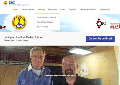 The Burlington Amateur Radio Club (BARC) provides a community hub for amateur radio operators in Burlington, Ontario, Canada, offering regular meetings, educational programs, and a dedicated hackspace for electronics and radio experimentation. The club operates several repeaters, including a 2m repeater (VE3RSB) on 147.210 MHz with a +600 kHz offset and 131.8 Hz tone, which supports AllStar node 542490. Additionally, BARC maintains a UHF repeater on 444.825 MHz with a +5 MHz offset and 131.8 Hz tone, and a 1.25m (220 MHz) repeater, facilitating local communication and digital mode access. BARC hosts multiple nets, including a Fusion Net on Mondays at 8:00 p.m. via VE3RSB-Room 61272, a Regular Wednesday Night Net on the VE3RSB system at 7:30 PM, and a 220 Net on Thursdays at 7:00 p.m. The club also runs a CW/SSB HF Net every Thursday at 7:00 p.m. local time on 40m, utilizing 7.125 MHz for LSB and 7.124.3 MHz for CW check-ins. These activities promote on-air participation, technical skill development, and social interaction among members, supporting both VHF/UHF local operations and HF DXing.
 -
 Constructing a dual-band antenna for 40 and 20 meters often involves compromises in size or complexity. This resource presents a compact _open sleeve dipole_ design that addresses these challenges by using 450-ohm ladder line and folded elements to achieve a total length of approximately **17.17 meters**, significantly shorter than a full-size 40-meter dipole. The design leverages electromagnetic coupling, where a primary radiator handles the 40-meter band, and a second conductor resonates on 20 meters without direct electrical connection. This configuration eliminates the need for traditional traps, loading coils, or switching components, simplifying construction and reducing potential loss points. The antenna is fed with RG-58C/U coaxial cable, and a common-mode choke is recommended at the feed point to suppress sheath currents, ensuring a cleaner radiation pattern and minimizing RF in the shack. The design is well-suited for portable operations, field deployments, temporary installations, and restricted urban environments where space is a premium, offering solid performance on both HF bands.
 -
 A review of the SteppIR UrbanBeam antenna a two element Yagi antenna working 40-6 meters. The UrbanBeam is a good choice for those thare are limited by lot size, regulations, city regulations.
 -
 A pocket-sized homebrew 40m CW QRPp/QRP transceiver
 -
 On the field comparison among C-Pole antenna, an EFHW vertical antenna and an Inverter V dipole antenna. Test is done using two identical WSPRLite beacons that transmit with 200mW on the WSPR frequency and analyzing spotted results.
 -
 Vertical end fed antenna used for portable operations. The antenna will work on 80 with acceptable results, it will work fine on 40m, and it will be a good deal better than a normal 1/4 wave GP on 20, 17, 15 meters.
 -
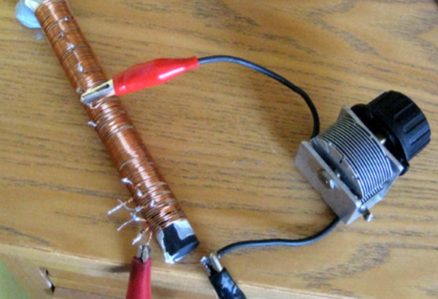
 A mircovert antenna assembled for the 40m version of the DL7PE antenna. A one meter long aluminum tube with 24mm diameter is used for the base (element 1) and a 50cm aluminum tube with 20mm diameter for element 2 (the extention). A pvc pipe, 34cm long and with a diameter of 38mm, is used to wind the coil on (1mm enamelled copper wire).
 -
 Listen to online WebSDR located in Andorra Europe. Four receivers on 60m, 20m, 40m, and 80m, connected to a dipole antenna direction East/West
 -
 Operating as FY/F5UII, Christian F5UII conducted a DXpedition to French Guiana (FY) from January 13 to 30, 2013. The primary operation utilized the FY5KE radio club station in Kourou, with activity focused on voice modes during specific weekday hours. The resource details the operator's intent to transmit before 12:00z and after 22:00z, or as availability permitted, from the mainland. A significant aspect of this operation involved a dedicated weekend activation of the Salut Islands, specifically **IOTA SA-020**, from January 19-20, 2013. This segment of the DXpedition was conducted from Royal Island (Ile Royale), part of a group including Devil's Island (Ile du Diable) and St. Joseph Island (Ile Saint Joseph), located 14 km offshore from Kourou. The station setup for the IOTA activation included 100 Watts of power, a GPA-030 vertical antenna for 10m, 15m, and 20m, and dipole antennas for 17m and 40m, with antenna deployment contingent on site conditions and propagation. The operator anticipated strong interest for the SA-020 entity.
 -
 F4DTO/ZA and F4GFE/ZA Albania 2 to 16 April 2011 40m to 10m
 -
 Results or performance test using an harpin antenna for the 7 MHz
 -
 A very essential j-pole antenna for 144 MHz. To adjust the SWR you will have to play with the 40mm distance between the coax feed and the braid inner conductor connection
 -
 The longest element has a total length of 14m and has a boom length of 5.5 meters featuring a total bandwith of 166 kHz
 -
 A dual band 40-80 vertical antenna on an 18m Spiderbeam Fiberglass Spiderpole, with monoband performance
 -
 This article documents the author's journey in building, modifying, and testing a DIY short vertical antenna for 40, 30, and 20 meters, with potential 80m capability. Initially inspired by Parks On The Air (POTA), the author explores pedestrian mobile operation and details various experiments to enhance antenna performance. The piece highlights challenges, SWR tuning, portability, and practical results, emphasizing a balance between efficiency and size. Ultimately, it showcases the adaptability of DIY antennas for portable ham radio applications.