Search results
Query: 6m
Links: 352 | Categories: 2
-
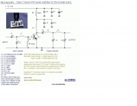 Class C tuned VHF power amplifier for the 6-meter band by ON6MU
 -
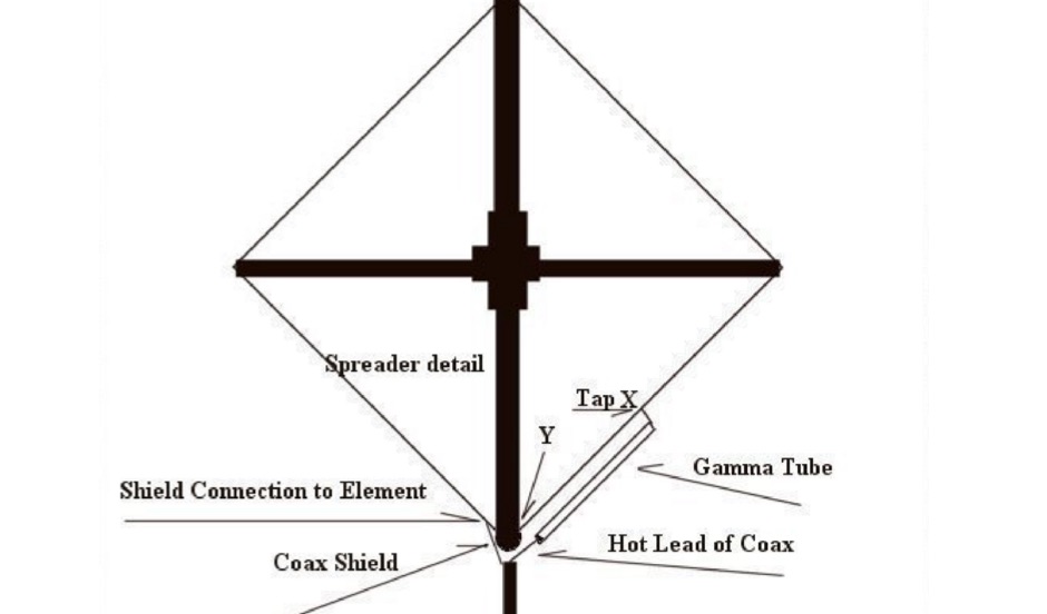
 An interesting homebrewed gamma match feed for a Halo Antenna
 -
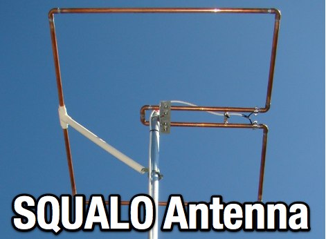 A SQ Loop antenna for 50 MHz, project include pictures and schematic diagram
 -
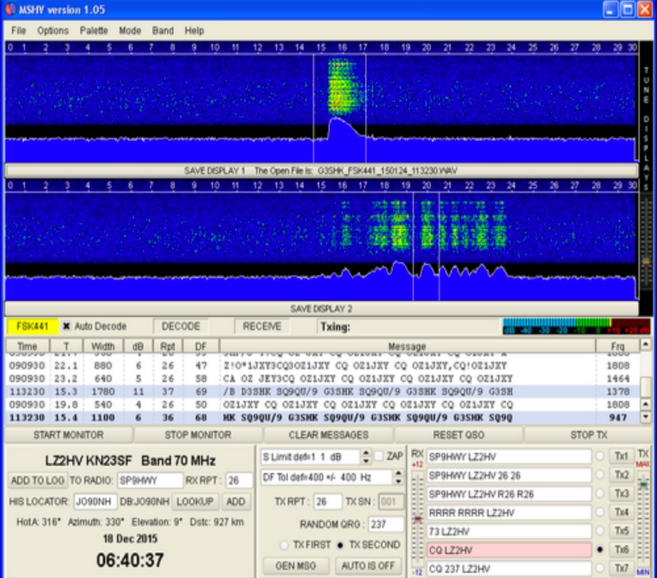 MSHV is a free windows and linux multimode software that support weak signal digital modes like MSK144 MSKMS JTMS FSK441 FSK315 ISCAT JT6M FT8 FT4 JT65 PI4 amateur radio modes. MSHV features several interesting features including the Multi Answering Auto Seq Protocol, allowing multiple signal transmissions to be used during dx peditions.
 -
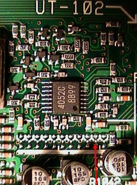 This modification will allow the MkIIG to transmit on most of the frequencies that it receives on.
 -
 The GW3YDX Super Moxon antenna design improves upon the standard Moxon Rectangle by incorporating additional directors in a rectangular configuration, yielding enhanced directivity and gain. For the 6m version, modeling with 4NEC2 and EZNEC+ indicated a 3dB gain increase and a 26.5dB front-to-back ratio, with VSWR below 1.5:1 between 50.0 and 50.3MHz when optimized for 50.1MHz. This design achieves a narrower -3dB power point beamwidth of 60° compared to the original Moxon's 80°, contributing to better QRM rejection. The boom length for the enhanced design is just under 2m, approximately double the original Moxon's, with no increase in wingspan. Construction details include tubing lengths for 6m, 4m, and 2m versions, with specific dimensions provided for elements A through M, measured to tubing centers. For instance, the 6m version uses a 2160mm element A and a 2140mm element H. The design maintains a 50-ohm feed impedance, with practical models showing VSWR plots consistent with simulations after minor adjustments to driven element lengths. The article also references Moxgen software for initial Moxon parameter calculation and NEC/EZNEC model generation. The 2m Super Moxon version measures approximately 30" x 25", demonstrating the compact nature of the design across different VHF bands. The article highlights the antenna's performance in real-world DX contacts on 6m, achieving contacts with over 80 stations in the USA from a modest QTH.
 -
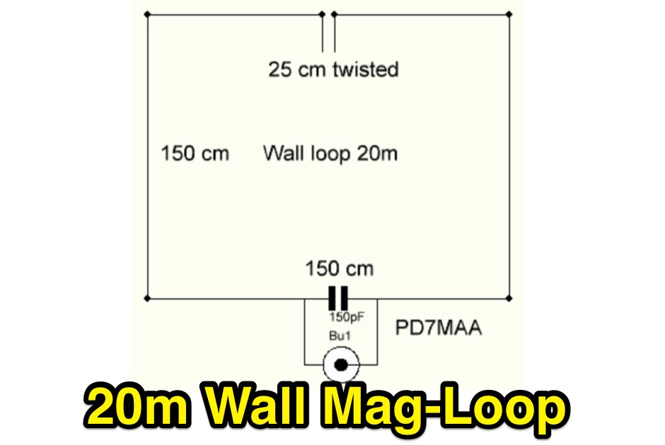 This max size magnetic loop antenna for 14 MHz with a totall circumference of 6m is designed to attach to a wall
 -
 Extension to an existing fan dipole originally modeled for 40 20 and 6 meters. This modification will add 80 15 and 10 meter bands.
 -
 2 x GI7B in push-pull 2m and 6m 1kW Power amplifier from PA0ZH
 -
 Modification to connect a frequency counter to a MFJ-9406 50 MHz transceiver by ON6MU
 -
 A 4 AMP / 18V regulated power supply schematic, designed by _ON6MU_, provides a detailed circuit diagram for constructing a robust power source. The design focuses on delivering a stable 18-volt output at up to 4 amperes, crucial for powering various amateur radio equipment. This resource presents a clear visual representation of component interconnections, including rectifiers, filter capacitors, and voltage regulation stages, essential for DIY enthusiasts building their shack infrastructure. The schematic's clarity facilitates understanding the power flow and component roles within the circuit. This circuit design offers a practical solution for hams needing a reliable 18V supply, potentially useful for driving specific transceivers, amplifiers, or accessory circuits. While specific performance measurements or comparisons to other designs are not detailed, the schematic itself serves as a foundational blueprint. Builders can adapt or modify the _power supply_ to suit their particular needs, such as integrating overcurrent protection or fine-tuning the output voltage with adjustable regulators. The straightforward presentation makes it accessible for those with basic electronics knowledge to assemble and troubleshoot.
 -
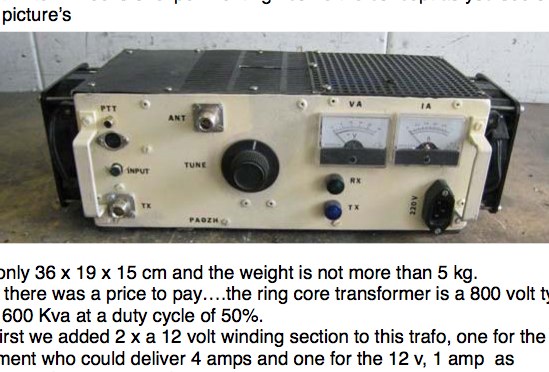
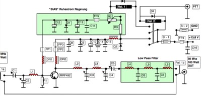 6-Meter Solid-State 100W Linear Amplifier complete documentation German and English
 -
 The resource presents a detailed schematic for constructing a dual-band vertical antenna, specifically designed for operation on the 2-meter and 70-centimeter amateur radio bands. It illustrates the physical layout, critical dimensions, and component placement necessary for successful replication. Key elements such as the radiating elements, phasing sections, and feed point are clearly depicted, providing a visual guide for radio amateurs undertaking a homebrew antenna project. The diagram specifies the lengths for the VHF and UHF sections, indicating how these elements are integrated to achieve dual-band functionality from a single coaxial feedline. It also implies the use of common materials readily available to most experimenters, focusing on simplicity and effectiveness in its design. The visual format of a GIF image ensures direct access to the construction details without requiring extensive textual interpretation. This schematic serves as a practical reference for hams interested in building a compact, efficient vertical antenna for local and regional FM communications, offering a proven design for immediate implementation.
 -
-
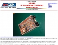
 Presents a QRP AM/CW transmitter project specifically designed for the 10-meter band, utilizing a crystal oscillator and a collector-modulated AM oscillator. The design employs a 2N2219(A) transistor in a Colpitts configuration, generating 100 to 350 mW of RF output power depending on the 9-18 Volt supply voltage and modulation depth. Frequency stability is maintained by a 28 MHz crystal, with fine-tuning possible via a Ct1 trimmer capacitor for approximately 1 kHz adjustment. The resource details the RF oscillator stage, implemented with a 2N2219 NPN transistor, emphasizing frequency stability and low power dissipation. It also covers the amplitude modulation stage, managed by a 2N2905 PNP transistor, which impresses audio information onto the carrier. Selective components (C3, C4, C7, C5) enhance voice frequencies within a +/- 5 kHz bandwidth, and modulation depth is controlled by R2 and R3. The project includes a 3-element L-type narrow bandpass filter (Ct3, L3, C10) to suppress harmonics and ensure a clean output signal. The project provides a complete schematic diagram, a comprehensive parts list including specific capacitor, resistor, and inductor values, and construction notes for the coils (L1, L2, L3). It also offers practical advice on enclosure requirements, suggesting an all-metal case or a PVC box with graphite paint for RF shielding. Operational parameters such as current draw (27mA@9V to 45mA@16V) and input impedance (50 Ohms) are specified, alongside guidance on antenna matching and the importance of a valid amateur radio license for 10-meter band operation.
 -
 A Variable Base-Loading-Coil provides a practical solution for optimizing HF mobile whip performance across multiple bands. The design, as presented by VK4ADC, details a coil wound on a 50mm PVC former, utilizing 1.6mm enamelled copper wire for robust construction. This approach allows for precise tuning, a critical factor in achieving efficient radiation from a mobile setup, where antenna length is often compromised. My own field experience with similar base-loaded whips confirms the importance of a well-designed loading coil for maximizing signal strength and minimizing SWR. The VK4ADC design incorporates a sliding contact, enabling continuous adjustment, which is superior to fixed taps for fine-tuning resonance on the fly. This variable inductance allows the operator to quickly adapt the antenna to different HF segments, from 80 meters up to 10 meters, without needing to swap out multiple coils. The document includes specific winding data, such as the number of turns per inch and the overall length of the coil, which are essential for replication. It also touches upon the mechanical aspects of integrating the coil with a standard mobile whip, ensuring a stable and weather-resistant assembly for reliable operation during mobile DXing or casual rag-chewing.
 -

-
 The webpage provides guidance on working 6 Meter DX, focusing on effective operating habits, preparation, and knowledge of the band. It emphasizes the importance of monitoring, clear frequencies, and using CW for weak signals. It also mentions the significance of knowing countries and individual stations on the air to increase chances of working DX. The page recommends utilizing resources like newsletters and websites to stay updated on 6-meter activity and offers suggestions for improving operating skills.
 -
 A two meter Quad antenna project with detailed instructions on how to adjust the Quad gamma match
 -
 1296MHz M57762 * 16 Power AMP 16V 100A 1.6KW Input
 -
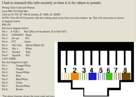 Wiring Color Code and Pinouts for IC-706MkIIG and HM-103 Mic
 -
 This article compares two commercial vertical antennas for the 4-meter amateur radio band: the Watson WVB-70 half-wave and the Sirio CX4-71. The Watson measures 2.03m in length, costs around £40, and exhibited adequate performance but required additional waterproofing after rain affected its VSWR readings. The longer Sirio CX4-71 (3.02m) performed noticeably better, delivering signals approximately 2 S-points stronger than the Watson. The Sirio demonstrated high build quality, a stable 1.2-1.4:1 VSWR, and weather resilience, though minor VSWR fluctuations were observed during rain and frost. Both antennas are half-wave designs requiring no ground plane radials.
 -
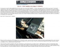 You wanna try to work modern satellite like AO-40 but have only one rig ICOM-706MKIIG ? This article will help you.
 -
 One of just a few webpages for the magic band, see it from the german point of view.
 -
 An example of how to control a Yaesu FT-817 with an Arduino to make a multi-band CW beacon.
 -

-
 Demonstrates the adaptation and construction of a 7-element DK7ZB Yagi antenna for the 4-meter band (70 MHz), utilizing components from a defunct 2-meter CUE DEE Yagi. The resource details the modifications made to the original DK7ZB design to fit the shorter CUE DEE boom length, specifically adjusting element lengths for 6mm rod elements while reusing existing mounting holes for the reflector and last director. It provides precise element lengths for the reflector, dipole (12mm aluminum tube), and five directors, along with a note on cutting elements for transport. The article includes a 4NEC2 simulation file for performance analysis and an SWR plot, confirming the antenna's electrical characteristics. It also specifies the calculation for the quarter-wavelength matching cable using SAT752F coaxial cable, resulting in a 909mm length. Practical application is shown with the finished antenna in operation at JO20XC, listing several activated Maidenhead squares such as JO56PA and JP40KS, validating its effectiveness for portable 70 MHz operations.
 -
 Digital amateur tv and mobile transmitting around Friedrichshafen and Lake Konstanz to be seen in Hall A. Heinz DC6MR is presenting the news, novelties and technical aspects of DATV.
 -
 A simple low-power broadcast-type circuit, using a crystal oscillator integrated circuit and an a collector modulated AM oscillator
 -
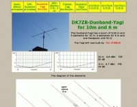 This Duoband-Yagi has a boom of 3.60 m and 3 elements for 10 m 4 elements for 6 m and one feedpoint with 50 Ohm
 -
 Links and sources of information about our club in Ventura County, California
 -
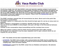 The Mt.Vaca Radio Club (Call sign K6MVR ) owns and operates repeater systems in and around Sacramento, California. The systems provide reliable coverage for mobile stations throughout the Sacramento Valley region and beyond to Modesto, Chico, the Sierras, and parts of the Bay Area.
 -
 Dedicated to 50MHz and 144MHz. Online 2m and 6m logs. Real Audio sound clips of Tropo, Aurora, Sporadic E, Meteor Scatter, TEP and F2 Propagation.
 -
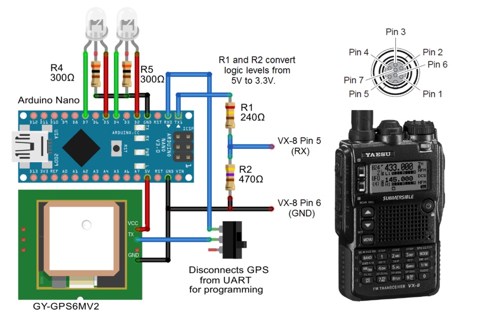 GPS module for Yaesu VX-8DR/DE handheld transceivers with ublox NEO-6M chip and Arduino Nano.
 -
 A home made dipole antenna for 10m, 6m, 4m bands made with two sections of 450 and 300 Ohm ladder lines, cut to achieve acceptable SWRs on all bands
 -
 This free program calculates the location of any locator. It calaculates the distance, azimuth, longitude and latitude between two Maidenhead locators. Converts longitude/latitude coordinates to Maidenhead locator Converts Maidenhead locator to longitude/latitude coordinates
 -

-
 10 meter propigation beacon project
 -
 The X80 multi-band HF vertical antenna, a commercial iteration of the Rybakov design, exhibits a physical length of 5.5 meters, or approximately 18 feet, and is constructed from aluminum tubing. It operates as a non-resonant vertical, requiring an external antenna tuner for impedance matching across its intended operating frequencies. The antenna's design incorporates a 1:4 UNUN at its base, facilitating a nominal 50-ohm feed point impedance for the coaxial cable. Performance observations indicate effective operation on 40 meters, 20 meters, 15 meters, and 10 meters, with reduced efficiency on 80 meters and 160 meters due to its relatively short electrical length for these lower bands. Comparative analysis with a G5RV dipole and a half-wave end-fed antenna reveals the X80 offers a lower take-off angle, beneficial for DX contacts, particularly on the higher HF bands. Field tests conducted with an Icom IC-706MKIIG transceiver and an LDG AT-100ProII autotuner demonstrate the X80's ability to achieve acceptable SWR across 80m through 10m. The antenna's compact footprint and ease of deployment make it suitable for restricted spaces or portable operations, though its performance on 80 meters is noted as a compromise compared to full-size resonant antennas.
 -
 6 Meter 1/4 Wave Antenna by Mike Fedler N6TWW. A detailed article with pictures of construction details of this 50 Mhz antenna
 -
 OE-information, firsts list, 250+ links to 6m pages and resources by OE4WHG
 -
 Crank-up(telescopic) and tilt-over tower, Ring rotator for mounting an extra antenna, from 16m to 42m, Strong safe and smooth, Radio communication and commercial tower.
 -
 This is a video review of the yaesu ft-450 amateur radio transceiver. This radio operates on hf and 6m with a built in antenna tuner.
 -
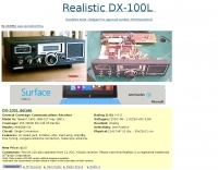 Modifications and improveents for the realistic DX-100L HF receiver by ON6MU
 -
 News of latest radio activity, initial contacts list, recordings of EME signals, information about station, and overview of latest projects.
 -
-
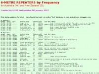 Presents a detailed compilation of **6-meter** voice repeaters operating within the 53-54 MHz segment across Australia (VK) and New Zealand (ZL), providing essential data for local and visiting radio amateurs. Each entry specifies the repeater's output and input frequencies, its assigned callsign (where applicable), the primary service area, current operational status (e.g., operational, under construction, scrapped), and a **Maidenhead grid locator**. The resource also includes the date the repeater was last heard or updated, offering insights into its recent activity. This listing is meticulously maintained by VK2KFJ, who updates entries based on personal observations and confirmed reports from other operators. It serves as a practical reference for hams seeking to utilize the 6-meter band for local communication via repeaters, particularly for those engaged in mobile or portable operations within the specified regions. The data helps operators configure their transceivers correctly for accessing these vital communication hubs. Beyond the repeater details, the page also notes common 6-meter FM voice simplex frequencies, such as the 52.525 MHz international call frequency, and lists historical packet simplex frequencies, though their current operational status is uncertain. This comprehensive approach ensures that operators have a broad overview of 6-meter activity in VK and ZL.
 -
 Over 100 amateur radio beacon audio files are presented, offering a direct auditory experience of propagation conditions across a wide spectrum of frequencies, from 1.8 MHz to 47 GHz. These recordings, primarily captured by IW3FZQ and IK3NWX, document signals from beacons such as DK0WCY, IY4M, GB3RAL, and S55ZRS, providing a valuable resource for **propagation study** and **beacon monitoring**. Each entry in the list specifies the beacon's callsign, its operating frequency in kHz, and the recording operator. This compilation includes signals from beacons located in various grid squares like JN55VF, JO44VQ, and IO91IN, illustrating diverse geographical origins. The frequencies covered span the 160m, 80m, 40m, 30m, 20m, 17m, 15m, 12m, 10m, 6m, 4m, 2m, 70cm, 23cm, 6cm, 3cm, 1.2cm, and 6mm amateur bands. Users can listen to these recordings to identify characteristic beacon tones and observe signal strength variations. The resource also invites other radio amateurs to contribute their own beacon audio files, fostering a collaborative archive of propagation data. The last update to this collection was on March 24, 2009, indicating a historical snapshot of beacon activity. Accessing the files requires the Real Player software.
 -
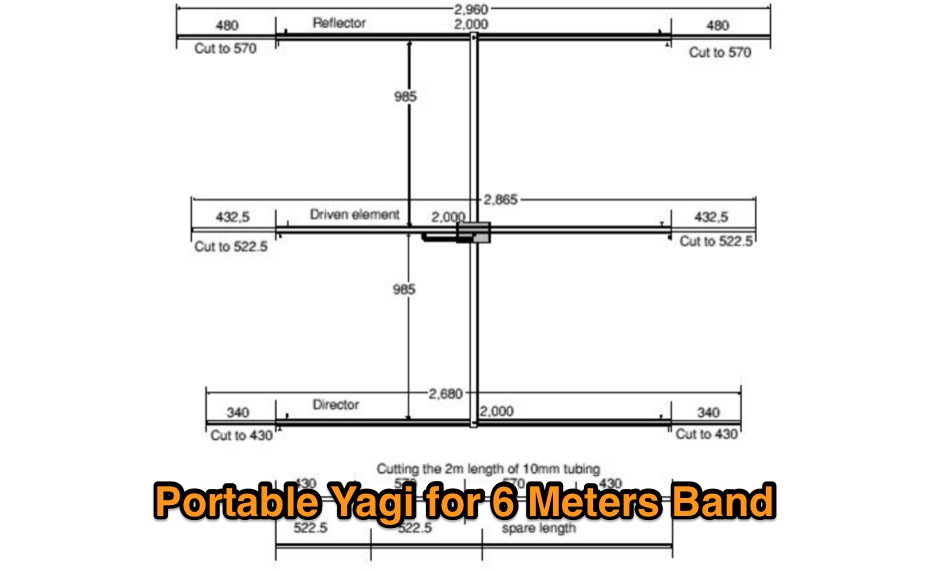 A portable three element 6M yagi for less than twenty pounds
 -
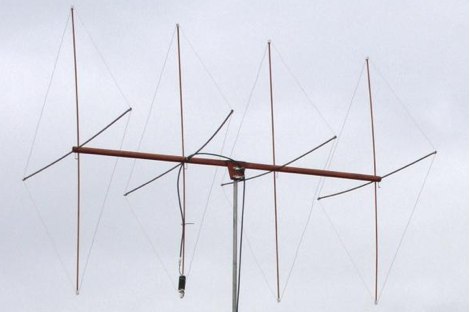 Article by G4AON about a 4 and 2 Element Quad Antennas for the 6m band