Search results
Query: ERP
Links: 189 | Categories: 0
-
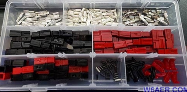 How to build and secure Anderson Power Pole Connectors properly
 -
 Steve Nichols, G0KYA, presents a practical examination of ground systems for vertical antennas, drawing heavily on the empirical research of Rudy Severns, N6LF. He explains that a robust radial field is crucial for ground-dependent verticals, effectively replacing the antenna's "missing half" and mitigating severe RF absorption in lossy soil. Nichols clarifies that surface radials do not strictly require a quarter-wavelength; instead, deploying a minimum of 16 to 32 shorter wires often yields superior results compared to fewer, longer ones. The presentation also addresses the common SWR paradox: a poor ground might show a perfect 1:1 match, but adding radials, while potentially raising the SWR to around 1.4:1, significantly improves true radiation efficiency. Nichols defines counterpoises as elevated wire networks that substitute for earth connections, offering solutions for limited-space installations, such as the **Folded Counterpoise (FCP)** for 160 meters. This resource provides actionable engineering data for optimizing vertical antenna performance.
 -
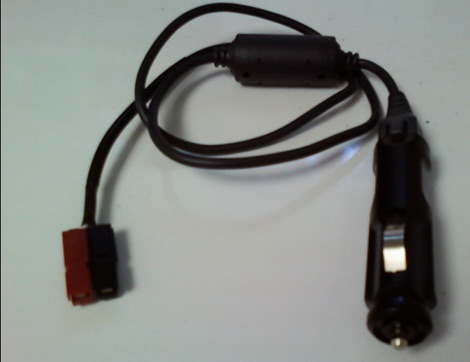 A useful and simple project to convert an unneeded car power cable to an Anderson PowerPole adapter.
 -
 This article describes the construction of a simple dual-band VHF/UHF end-fed vertical dipole antenna designed for local repeater access using an Icom IC-705 radio. Built from a single piece of RG58U coaxial cable, the antenna consists of a 460mm exposed inner conductor, 450mm of intact coax, and a 9-turn choke balun wound on a 27mm former. Mounted on a 10m Spiderpole, the antenna achieves excellent SWR readings (<1.2:1 on 2m, <1.5:1 on 70cm) and provides effective coverage of local repeaters with unexpected reach into distant locations.
 -
 A Magnetic Loop Controller project details the construction and operation of an automatic tuning system for magnetic loop antennas, which are resonant circuits using an oversized inductor and an adjustable capacitor. The system employs a stepper motor to precisely adjust the variable capacitor, maintaining optimal resonance across the HF bands. It integrates with various transceivers, including _Icom_, _Kenwood_, and _Yaesu_ models, by monitoring the VFO frequency and adjusting the loop's tuning accordingly. The project provides comprehensive building instructions, a PowerPoint-style presentation, and the full source code for the controller's firmware, enabling hams to replicate and customize the design. The controller's firmware offers diverse functionality, including automatic frequency tracking, manual tuning, and SWR monitoring, significantly enhancing the operational efficiency of magnetic loop antennas, particularly for QRP and portable operations. The design emphasizes accurate capacitor positioning, crucial for achieving low SWR and maximum radiated power. Comparisons with manual tuning methods highlight the benefits of real-time adjustment, especially when operating across different bands or making frequent QSYs. The project's detailed documentation and available source code facilitate experimentation and modification by advanced builders, allowing for tailored performance characteristics.
 -
 In this post, we describe how to make a pigtail cable to connect the Kenwood TH-F6A triband HT to a 12Vdc power source via an Anderson PowerPole connector.
 -
 Presents a detailed construction guide for a 9 dB, 70cm collinear antenna, utilizing readily available _RG58/U_ coaxial cable and PVC pipe for housing. The resource outlines the critical calculations for ½ wavelength sections at 444 MHz, incorporating the coaxial cable's velocity factor of 0.66, which yields a section length of 223 millimeters. It specifies the preparation and soldering of eight such half-wavelength sections, each cut to 231mm to allow for trimming, forming the core of the array. Further instructions detail the integration of a ¼ wave element (169mm #16 solid wire) at the top and a ¼ wave aluminum tube (160mm, 5/16 inch) at the bottom, crimped to the feed point's braid. The guide also addresses RF common mode current suppression by suggesting the use of _FT50-43_ toroids on the feedline. Final assembly steps cover mounting the antenna within ¾" PVC pipe using a wooden dowel, waterproofing connections, and initial SWR checks. The article also discusses scaling the design for different element counts and other VHF/UHF bands.
 -
 This DIY homebrew project provides a durable, weatherproof center connector for dipole antennas, ideal for HF setups like 40m wire dipoles or inverted-V designs. Made from PVC pipe and an SO-239 UHF connector, it ensures strong support and room for a current balun. With simple drilling and assembly, it offers a cost-effective alternative to commercial options. Perfect for amateur radio operators, this dipole antenna connector enhances performance while keeping costs low. A great solution for DIY antenna builders seeking reliability and longevity.
 -
 An cheap and efficient wire antenna for lower HF bands. This closed loop antenna, radiates perpendicular to its plane with a bi-directional radiation pattern. With a gain of 2 dB over a diplole it is a low noise sensible antenna. Requires a tuner if you want to use as a multiband antenna.
 -
 A data converter for the Tandy WM918 weather station. The Weather APRS data converter project aims to create an interface to interpret data from the popular Tandy WM918 weather station and format it for transmission over packet radio. The South East Radio Group in South Australia has established a network of these weather stations to provide amateurs with regularly updated weather data. However, the WM918's data output is not structured for APRS weather reporting. This project describes a solution using a PIC microcontroller to convert the WM918 data into APRS-compatible strings that can be sent as beacons or connected packets. The interface offers features like position/positionless data, connected/beacon modes, and metric/imperial units. The goal is to create an interconnected weather reporting system for amateur radio operators
 -
 It is very worthwhile to understand how Beverages of all types work. Without that understanding it can be quite difficult to interpret what you hear and what you measure.
 -
 This article addresses the issue of unwanted RF in amateur radio setups and introduces a practical method to measure common-mode currents (CMC) using a homebuilt RF meter. The meter, constructed with readily available materials, measures unwanted RF on the coaxial cable shield by inductively coupling to the shield using a split-bead ferrite. The article provides detailed instructions on building the meter, interpreting measurements, and using ferrite chokes to mitigate RF interference. Emphasis is placed on the importance of verifying CMC levels and installing chokes to improve equipment performance.
 -
 WB5NHL describes setting up a 160-meter antenna on a small suburban lot, where standard options like Beverage antennas and 1/4 wavelength verticals require extensive space and ground systems. Instead, Guy Olinger's Folded Counterpoise (FCP) provides a solution. The FCP minimizes ground losses by using a folded wire design, allowing effective antenna placement in limited space. The FCP, fed with an isolation transformer, enabled WB5NHL's first 160-meter antenna installation, offering improved performance despite space constraints.
 -
 The 1/4 wavelength vertical antenna project, initially designed for 20 meters, has evolved into a versatile portable solution covering 10 through 60 meters. K0BXB details its construction, emphasizing a bottom-loaded design with a tapped loading coil and four 10-foot counterpoise wires. The author shares personal experiences and field results, including **18 QSOs** during a park activation on 17m and 30m with 10 watts, and a **2,435-mile** contact with a contest station in Bonaire on 20m using 5 watts. Comparisons are drawn to commercial offerings like the _Wolf River Coils TIA_ and _QRPGuys Triband Vertical_, highlighting the DIY antenna's small footprint, light weight, and ease of tuning for POTA activations. The resource includes insights into using test equipment such as the _NanoVNA_ for SWR optimization and discusses various radiator lengths, from 17-foot wire to a 102-inch whip, demonstrating adaptability for different portable setups. Construction tips cover coil winding, tap placement, and connecting feedlines and radials using common components.
 -
 Constructing a double bazooka antenna for the UHF band, specifically tuned for 435 MHz, involves a straightforward process detailed with step-by-step imagery. The design leverages readily available _RG213 coaxial cable_, cut to precise lengths derived from formulas: 140.208 / F (MHz) for the radiating element and 99.06 / F (MHz) for the coaxial section. This approach yields a highly effective vertical polarization antenna, suitable for local ragchewing or repeater access. My own field experience with similar coaxial designs confirms their robustness and ease of deployment. The article emphasizes critical steps like short-circuiting cable extremities, interrupting the braid at the center, and securing an insulating support. It also covers preparing the definitive mounting with a quality feedline, noting that RG58 is acceptable for temporary use but better options exist for permanent installations. Weatherproofing is crucial for longevity, achieved through PVC electrician's tube, glue, and heat-shrink tubing. The final assembly is designed for mounting on a small aluminum mast, with the feedline routed internally. The reported SWR measurement is very satisfactory, showing approximately **+/- 3%** HF return, indicating excellent impedance matching at the target frequency.
 -
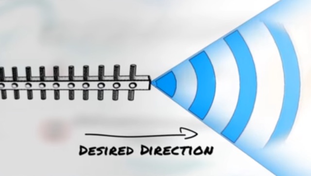 Approximately 3 minutes of video content, originally from _Aruba Networks_, illustrates fundamental principles of antenna gain and radiation patterns. While the source material targets broadband wireless, the underlying physics of RF energy directionality and signal shaping are universally applicable to amateur radio antenna systems across various frequencies. Antenna gain is crucial for maximizing effective radiated power (ERP) without simply increasing transmitter output. The resource explains how elements in a Yagi beam, for instance, absorb and re-radiate RF energy, cumulatively increasing signal amplitude in a desired direction. This process enhances both transmit efficiency and receive sensitivity, directly impacting DX capabilities and overall station performance. Understanding these concepts is paramount for any radio amateur, as the antenna system often represents the most significant factor in a station's operational effectiveness. The article emphasizes that careful calculation and positioning of parasitic elements can dramatically reshape an antenna's radiation pattern, leading to substantial improvements in signal strength and reach.
 -
 This document provides comprehensive guidance on modeling and constructing multiband dipole antennas using traps. It addresses common segmentation issues in EZNEC modeling software, recommends optimal segment lengths for trap models, and compares trapped dipoles with paralleled multiband dipoles. While trap dipoles are significantly shorter, they exhibit lower gain and narrower bandwidth. Detailed instructions for building weatherproof coaxial traps include material lists, construction steps, and tuning methods. The guide notes that properly constructed coaxial traps introduce only minimal signal loss (0.6 dB) while offering practical multiband performance in a compact design.
 -
 The article by Guy Olinger, K2AV, published in the May/June 2012 National Contest Journal, introduces the Folded Counterpoise (FCP), a compact 516-foot single-wire counterpoise elevated at 8 feet, designed for 160-meter operations on small lots like 100x150-foot backyards. Originating from efforts to revive Top Band for W0UCE on a postage-stamp property, the FCP uses strategic folds to cancel ground fields within 33 feet of center, minimizing losses to 0.13-0.53 dB—outperforming sparse or on-ground radials by up to 15 dB in poor soil—while mimicking opposed radials for efficient feedpoint impedance. Paired with a critical 1:1 or 4:1 isolation transformer (e.g., trifilar on T300-2 toroid) to block common-mode currents on coax feeds, it delivers proven results: K2AV's #8 North America low-power contest score, 7+ dB gains at W4KAZ and K5AF, and over 10,000 global web hits for DIY instructions using bare 12 AWG wire and weatherproof enclosures. Ideal for acreage-challenged hams, the FCP also excels on 80 meters with scaled dimensions, offering a low-loss alternative where full radials are impractical
 -
 Recently, at the Ballarat Hamfest, the author acquired an old Marine transceiver for just $10, charmed by its sturdy construction and waterproofing. Made by Findlay Communications in Sydney, this crystal-controlled transceiver had been dormant but was reinvigorated with minor fixes. A manual was sourced, and further repairs were made, including an ingenious crystal oscillator replacement using an Si5351a controlled by an Arduino. The refurbished radio, complete with a fresh coat of paint and added customizations, is now operational for 160m AM and 30m SSB. A successful and cost-effective restoration.
 -
 In his POTA activation, WK4DS experimented with radials for hamstick antennas. Despite sun and RF noise challenges, successful connections were made. Surprisingly, tuned radials proved unnecessary, simplifying setup. Hamsticks demonstrated versatility across frequencies. Increased power improved signal quality, sparking his curiosity for further exploration in radio technology.
 -
 A custom center hub for a Spiderbeam yagi antenna, enabling side-mounting on an existing mast. Challenges included structural instability, limited reach for assembly, and interference with a pre-mounted Spiderpole. A new hub using 40x40mm aluminum tubing provided strength, allowed side assembly, and supported fiberglass pole guy lines. The solution facilitated efficient installation and removal, delivering excellent performance compared to a SteppIR yagi.
 -
 This document serves as a reference guide for pilots interpreting the symbols used on Instrument Flight Rules (IFR) Enroute Low and High Altitude Charts for both the United States and Alaska. It focuses on six key categories of information critical for safe IFR navigation and it includes a section dedicated to Oceanic Route Charts for the North Atlantic and North Pacific regions.
 -
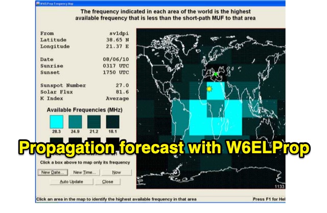 In 2004, Carl Luetzelschwab, K9LA, wrote a guide on using W6ELProp for radio wave propagation predictions. This tutorial, translated for broader accessibility, explains initial setup, configuration, and daily use. It emphasizes using mean solar index values for accuracy, helping users effectively predict and interpret propagation for improved amateur radio operations.
 -
 The article explores the concepts of return loss, VSWR, and S11 within the context of microwave engineering, highlighting the confusion arising from their definitions. It clarifies that these parameters, while seemingly distinct, fundamentally describe the same phenomenon related to wave reflection and transmission in microwave circuits. The discussion emphasizes the historical context and mathematical relationships among these terms, revealing that their interpretation can vary significantly across different engineering disciplines. Ultimately, it advocates for a pragmatic approach to using these parameters based on familiarity rather than strict definitions.
 -
 Moto-QRP setups offer compact, weatherproof QRP transceivers for portable ham radio use, ideal for motorcycle and backpack operations. The YouKits HB1A MKII, a 5W CW rig, is paired with a lightweight long-wire antenna and an Elecraft T1 tuner for efficient field communication. This setup fits in panniers, enabling operators to explore parks and remote locations. Accessories include a durable Morse paddle, FCC documentation, and essential logging tools, making it a perfect choice for adventurous QRP enthusiasts.
 -
 This article details an Inverted-L antenna design optimized for 160-meter band operation, consisting of a 10m vertical section and a 28m horizontal section supported by Spiderpoles. Despite its relatively low height compared to the wavelength, the antenna has demonstrated impressive DX capabilities, achieving contacts up to 3,453 miles into Asiatic Russia. The system incorporates a Pi-Network ATU at the base for tuning flexibility. While modeling shows a radiation pattern favoring the South, practical operation indicates effective all-round coverage on Top Band.
 -
 In this project by building a W2IMU feed horn, the author successfully optimized their 10GHz Small Dish EME project. To position and solder the components together, they used a jig and a conical section made of copper sheet. Stability was ensured by fitting the XLNA to the WG switch. The WG components were shod into a waterproof plastic container, and the feed horn and WG were surrounded by a collar and skirt that were 3D printed. With an average Moon noise of 0.5dB, the Sun and Moon noise readings were better than their previous configuration.
 -
 This report details a modification of a Diamond V2000 antenna, replacing its original two 0.50 m radials with two 1.55 m radials. Initial M5-threaded rods failed to fit; the housing required M6 threads. Custom radials were made using 8 mm OD aluminium tubing and M6-threaded stainless steel ends, secured with nuts machined to 9 mm. SWR issues on 6 m (>2:1) were largely due to a poor counterpoise connection, resolved during reassembly. NanoVNA measurements showed no adverse effects on 2 m or 70 cm. The final setup retains the two 1.55 m radials and original counterpoise. Other operators reported SWR degradation with similar mods—sometimes fixed by adding capacitance—but this was not observed here.
 -
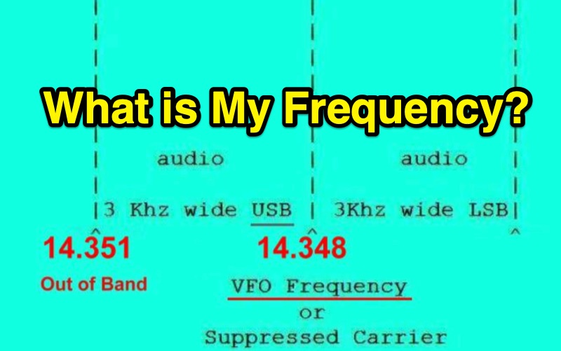 Single Sideband (SSB) operation requires careful attention to the relationship between a radio's displayed frequency (suppressed carrier) and the actual 3 kHz wide audio signal. This resource clarifies how Upper Sideband (USB) and Lower Sideband (LSB) signals occupy spectrum above or below the indicated frequency, respectively. It provides practical examples for General Class operators on the **20m** and **40m** bands, such as setting a VFO to 14.226 MHz for USB on 20m or 7.178 MHz for LSB on 40m, to maintain a safe margin from band edges. The resource emphasizes the critical importance of staying within allocated band limits to prevent out-of-band emissions, particularly when operating close to band edges. It includes relevant excerpts from **FCC Regulation Part 97**, specifically section 97.307, which details emission standards, necessary bandwidth, and spurious emission attenuation requirements. The text explains that unused sidebands are considered spurious emissions and notes that modern HF equipment typically exceeds the 43 dB spurious emission reduction standard, often achieving 60 dB or more.
 -
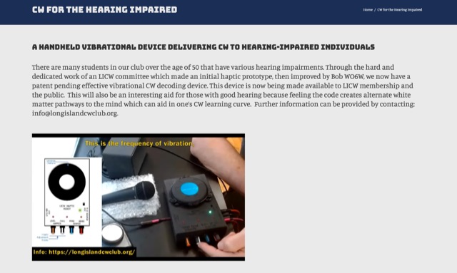 The resource details a novel approach to Morse code (CW) reception for hearing-impaired operators, focusing on a handheld device that translates CW signals into tactile vibrations. It explains how this device allows users to perceive the patterns of dots and dashes through physical feedback from a shaker, addressing the challenges of auditory discrimination for those with hearing loss. The content highlights the potential for this tactile method to aid in CW learning and interpretation, even suggesting benefits for operators with normal hearing by providing an alternative sensory input. The article also mentions the device's _patent-pending_ status and its availability to members of the _Long Island CW Club_ and the general public. It provides contact information for further inquiries about this innovative tool.
 -
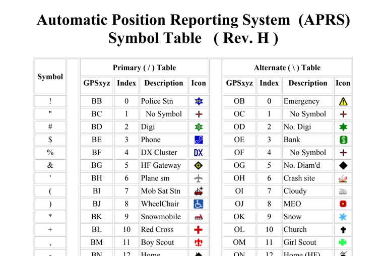 The four-page _APRS Symbol Table_ (Revision H) systematically lists 96 primary and 96 alternate Automatic Packet Reporting System symbols, each with its corresponding GPSxyz Index, a concise description, and a visual icon. For instance, the primary symbol '!' (GPSxyz BB) represents a "Police Stn," while its alternate counterpart '!' (GPSxyz OB) signifies "Emergency." The resource clearly delineates how specific ASCII characters map to distinct graphical representations on APRS displays, crucial for accurate situational awareness. It presents a direct, tabular format, making it an efficient reference for operators needing to quickly identify or interpret the myriad of icons used in APRS mapping applications. The table covers a broad spectrum of common APRS entities, from fixed stations like "Digi" (#) and "Home" (-) to mobile units such as "Car" (>) and "Plane sm" ('), alongside various weather phenomena and emergency services. Compiled by VK4KTP and featuring images by WA8LMF, the document serves as a definitive guide for understanding the visual language of APRS. It is particularly useful for those involved in tactical communications, public service events, or general APRS tracking, ensuring consistent symbol interpretation across different platforms and user interfaces.
 -
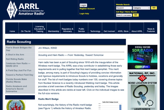 A web page dedicated to amaterur radio scouting. Scouting and Ham Radio — From Yesterday, Toward Tomorrow. Radio Merit Badge, Morse Code Interpreter Strip, Jamboree on the air
 -
 This page by ARCTICPEAK provides a calculator for determining ERP and EIRP (Effective radiated power and effective isotropic radiated power). The tool is designed to help hams calculate and understand the power radiated by their radio equipment. The content is useful for ham radio operators who want to optimize their transmission power and comply with regulations. LA8OKA Martin has created this resource to assist hams in accurately measuring their radio signals.
 -
 This project describes a high-performance EME antenna array consisting of two home-designed 9-element Yagis, each about 2.5 wavelengths long, combined into a 25-ohm system and matched to 100 ohms using 9/4λ sections of 50-ohm coax. The array supports rotatable polarity from 0° to 180°, allowing both horizontal and vertical polarization to optimize moonbounce performance under varying conditions. Despite operating for years without a balun—something another designer called “disastrousâ€â€”the system has delivered strong results, including copying very weak DX such as VK3KH at about -25 dB with only 120 W (around 2 kW ERP). The builder continues to refine the mechanics, having installed new gear motors and an upgraded follow-up control system in 2011.
 -
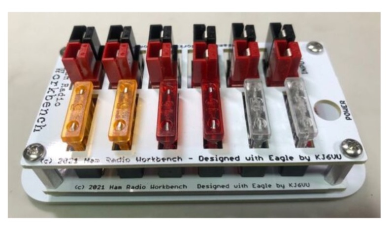 The **5-Port 12 Volt DC Power Strip Kit (Rev 4)** offers a practical solution for managing shack power distribution, providing one input and five fused outputs. All connections utilize the ubiquitous Anderson PowerPole connectors, a standard for many amateur radio operators, ensuring a clean, organized, and safe way to power multiple 12 VDC transceivers and accessories from a single source. This design mitigates the common issue of tangled wires and overloaded connections in a typical ham shack. Rated for a maximum current of 20 Amps at 12 VDC, the strip incorporates an integrated LED to indicate when external power is applied. Each output is individually fused, a critical safety feature that protects connected equipment from overcurrent conditions without affecting other devices on the strip. This level of protection is essential for preserving sensitive radio gear during operation. Assembly requires basic soldering skills and hand tools, with a high-power soldering iron and wide chisel tip specifically recommended for best results. The kit's compact dimensions of 4.13" x 1.78" allow for flexible mounting via screw holes, making it suitable for various shack configurations and portable operations.
 -
 A high-technology enterprise specializing in the R&D, production and sale of two-way radio equipment for over twenty years. DMR Radio, Digital and analog portable radio manufacturer based in China
 -
 Demonstrates the design and modeling of a **160m** vertical antenna, dubbed the "WindoVert," specifically for urban amateur radio operators with limited space. The resource covers the theoretical underpinnings of antenna height and radiation patterns, using EZNEC software to analyze current distribution and 3D radiation patterns for various configurations, including a Marconi-style "T" antenna. It details the integration of existing antenna components, such as a Carolina Windom balun and line isolator, into the new vertical setup, and the practical measurement of feedpoint impedance using an antenna analyzer. The article further explores the challenges of achieving low-angle radiation on Top Band, emphasizing the critical role of radial systems and mitigating ground loss. Author VE1ZAC presents EZNEC models illustrating the impact of lumped components and discusses the practical considerations of resonant frequency adjustment and impedance matching for **QRP** operation. The text details the calculation of required loading coil inductance and capacitance, and shares field results, including successful DX contacts on 160m and unexpected excellent performance on 30m.
 -
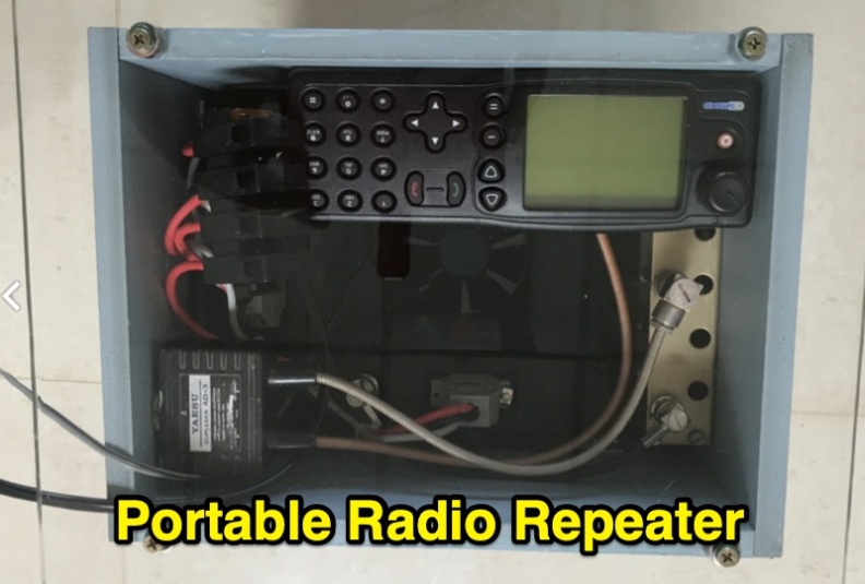 Demonstrates the construction of a portable 2-meter repeater system utilizing a **Yaesu DR-1X** transceiver, configured for both analog FM and C4FM digital voice operation. The design emphasizes portability, robustness, and effective thermal management, incorporating a "wind tunnel" airflow system with a fan to maintain transmit module temperatures at 38 degrees Celsius during continuous operation. The system integrates a diplexer, control head, and is housed in a compact, lightweight case weighing under 8kg, designed for single-person deployment. Covers practical considerations for field deployment, including power sources, antenna types, and the overall system architecture for public service events and emergency preparedness. The resource details the modular "wrap around" construction, showing how components like thermal switches for fan control and Anderson Powerpole connectors are integrated. It highlights the system's ability to provide reliable communications support for club activities and emergency communications.
 -
 The W6PQL 23cm Beacon Project describes a **1296 MHz** beacon designed for microwave propagation studies and equipment testing, capable of 30 watts output. It utilizes a PIC 16F628A microcontroller to generate CW and FSK keying for a crystal oscillator, followed by a series of frequency doublers and triplers to reach the target frequency. The final power amplification stage employs a Mitsubishi M57762 module, providing a robust 10-watt RF output. The design emphasizes stability and reliability for continuous operation, with the microcontroller code, written in assembly, provided for customization of the beacon's callsign and message. Originally located in CM97am and aimed at 140 true, the beacon used four 4-foot Yagis stacked vertically for a total ERP of 3kW. The article includes schematics, parts lists, and construction notes to guide builders, along with antenna pattern measurements. Although the beacon itself is no longer in service as of August 2010, the detailed documentation remains a valuable reference for amateur radio operators interested in building similar **microwave** projects or understanding beacon operation.