Search results
Query: add an s meter
Links: 166 | Categories: 0
-
 Details the installation and operation of the DX Engineering TFS Series Transmit Four Square System Phasing Units, specifically models like the DXE-TFS4-160B, DXE-TFS4-80B, and DXE-TFS4-40B. It covers system components, required parts, and a discussion of vertical antenna selection, including a table of suitable DX Engineering Monoband Vertical Antennas. Installation procedures are outlined, encompassing site selection, four square layout, topographical considerations, and noise source mitigation. Specific instructions are provided for mounting the phasing unit, antenna feedline connections using 1/4-wave 75-ohm coaxial cables, and control wire routing. The document also includes details on radial system implementation, with a table of radial wire lengths for 160, 80, 75, and 40 meters, and procedures for tuning the vertical antennas for optimal performance. Operational aspects of the Four Square Control Console are described, including front and rear panel functions, control logic (Table 4), and typical transceiver/amplifier interconnections. The system enables directional control with approximately 5 dB gain over a single vertical element in four directions or an omni-directional pattern, achieving typical front-to-back ratios exceeding 20 dB. Lightning protection and initial system testing are also addressed, along with a 5 kW CW and 10 kW PEP SSB power rating and hot switching lockout feature.
 -
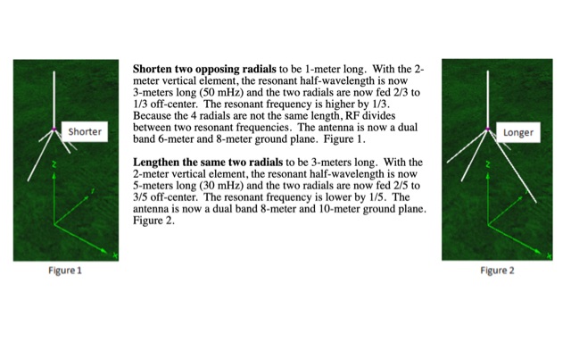 This article explains the trick of how to shorten and lengthen pairs of radials to make a 2-band ground plane antenna. Included is a "Table of Multi-Band Possibilities" covering the range of 6 to 40 meters.
 -
 This report details a modification of a Diamond V2000 antenna, replacing its original two 0.50 m radials with two 1.55 m radials. Initial M5-threaded rods failed to fit; the housing required M6 threads. Custom radials were made using 8 mm OD aluminium tubing and M6-threaded stainless steel ends, secured with nuts machined to 9 mm. SWR issues on 6 m (>2:1) were largely due to a poor counterpoise connection, resolved during reassembly. NanoVNA measurements showed no adverse effects on 2 m or 70 cm. The final setup retains the two 1.55 m radials and original counterpoise. Other operators reported SWR degradation with similar mods—sometimes fixed by adding capacitance—but this was not observed here.
 -
 Demonstrates the construction of an active loop converter specifically designed for the Low Frequency (LF) bands, addressing common localized noise interference in LF reception. The design integrates a sharply tuned circuit and a tuned loop antenna, utilizing the loop as the sole tuned inductive element. By applying positive feedback, the converter significantly increases the loop's effective Q, achieving factors between 1000 and 2000, which sharpens tuning and reduces noise. The circuit employs an _NE602_ mixer stage, feeding its output to an HF receiver, with a crystal-locked local oscillator at 4 MHz. A 20-turn, 0.8-meter square loop antenna with 500 uH inductance is detailed, connected via 2 meters of figure 8 flex cable. The converter offers three selectable frequency bands: 195-490 kHz, 150-220 kHz (including the New Zealand amateur band), and 128-160 kHz (covering the European amateur band). Performance measurements indicate an effective 3dB bandwidth of approximately 100 to 200 hertz at 200 kHz. The article provides insights into component selection, including an _LF353_ op-amp and a trifilar wound transformer on a ferrite core. Sensitivity figures are presented, showing 7.5 uV of converted output per 1 uV/meter signal strength into a 50-ohm load, or 37.5 uV into an _FRG7_ receiver, highlighting its capability to extract weak signals from noise.
 -
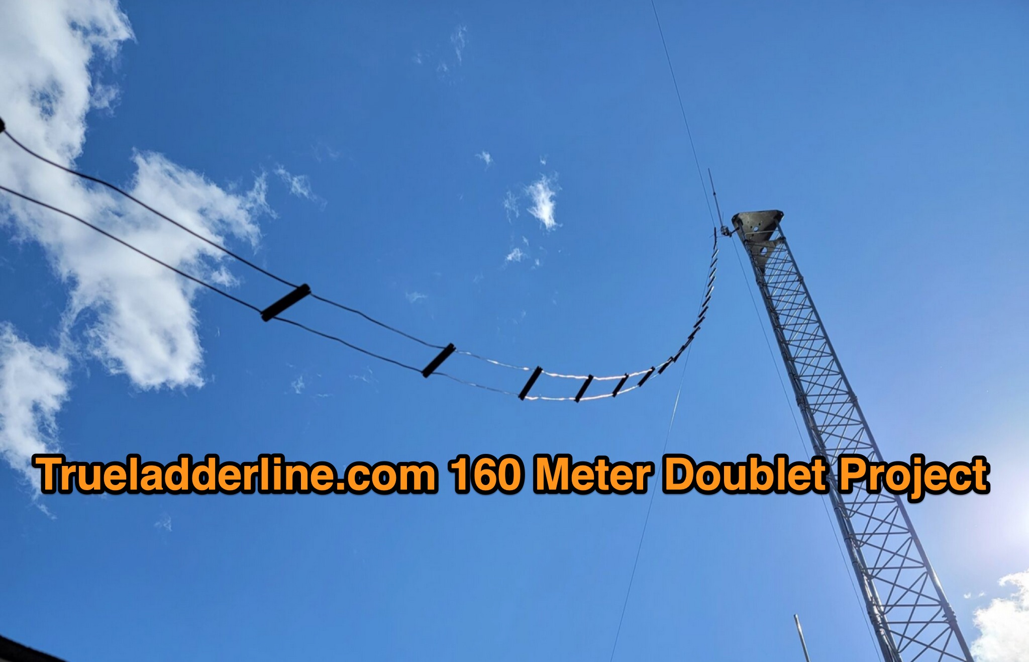 This page describes N6AQ's experience with a 160-meter doublet antenna from True Ladder Line. The operator initially attempted to install the antenna in a tree but later changed to a Rohn 45 tower for support. The antenna was upgraded to use 14ga wire instead of 16ga, and the performance was tested using an IC7300 transceiver with a 4:1 balun. Despite less than ideal setup conditions, the operator received positive signal reports on 40, 80, and 160 meters, thanks to advice from Gary at True Ladder Line.
 -
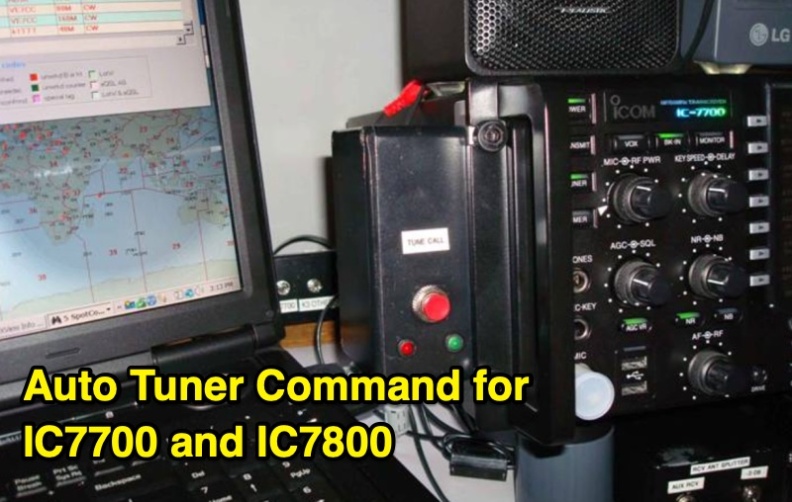 An Arduino-based interface provides a remote tuner call command for Icom **IC7700** and **IC7800** transceivers, addressing the lack of a built-in function for external tuners such as the MFJ 998RT. This setup initiates a low-power transmit signal, typically 15 watts, allowing the remote autotuner to perform its matching sequence. The article details the required CI-V line communication and modifications to existing Arduino code, specifically referencing contributions from Jean-Jacques ON7EQ for improved Icom interrogation routines. The system involves a sequence of steps: storing the transceiver's current mode and power, disabling the internal autotuner, activating a control relay to interrupt the amplifier line, switching to RTTY mode at low power, and initiating transmit. The transmit duration is manually controlled by the operator, observing the SWR meter until a low SWR is achieved, then a second button press stops the transmission. A built-in 4-second transmit limit provides a safety measure. After tuning, the routine restores the original mode and power settings, re-enables the internal autotuner, and performs a brief 2-second RTTY transmission for internal tuner adjustment. The circuit diagram includes a Panasonic form 2 relay for amp control and emphasizes critical delays in the Arduino code for stable operation at 9600 baud CI-V communication. Compatibility with logging software like DXLab, N1MM, and N3FJP is noted, with specific interrogation time settings required to avoid conflicts.
 -
 Demonstrates a specific impedance matching technique for resistive loads ranging from 22.2 to 45 ohms, connecting them to a 50-ohm transmission line. The method employs series sections of 50-ohm and 75-ohm coaxial cables, with graphical data illustrating the required cable lengths (L1 and L2) in wavelengths for a perfect match. This approach is particularly useful for feeding **vertical** and **Yagi antennas**. The resource provides a practical example of matching a 25-ohm Yagi antenna at 50.150 MHz, specifying the use of RG-58C/U (50 ohms) and RG-59B/U (75 ohms) cables, both with a 66% velocity factor. It calculates the precise physical lengths in centimeters and inches for the required cable sections. Additionally, the document briefly discusses integrating a balun at the load end, suggesting methods such as coiling a cable section or utilizing ferrite beads to create a W2DU-type balun. The presented methodology offers a clear, data-driven solution for common antenna impedance challenges.
 -
 Presents an online retail platform for amateur radio operators, showcasing a diverse inventory of equipment and accessories. The site lists popular transceivers such as the _Icom IC-7300_ and _Icom IC-7610_, alongside various antenna solutions including base, HT, mobile, and end-fed designs. Operators can find coaxial cable, including bulk options and products from "The Wire Man," essential for shack setup. The platform also stocks crimping and stripping tools, adapters, and power supplies, crucial for station maintenance and construction. Test equipment like _RigExpert Analyzers_ and accessories such as Daiwa meters and _West Mountain Radio_ Power Poles are available. Additionally, the site offers software from _Ham Radio Deluxe_ and _RT Systems_, catering to logging and radio programming needs. Shipping policies include free shipping on C.Crane Radios and most orders over $100.00 within the lower 48 states, providing clear purchasing incentives.
 -
 Constructing a **J-Pole antenna** from 450 Ohm ladder line for 2-meter (144 MHz) and 70-centimeter (440 MHz) operation involves specific calculations and assembly steps. The design, based on an earlier KD6GLF concept using 300 Ohm twinlead, features a ¾ wavelength radiator and a ¼ wavelength matching stub, functioning as an end-fed half-wave antenna without requiring ground radials. It offers a gain of 2.4 dB over isotropic. The resource provides the formulas for determining the lengths of the ¾ wave radiator and ¼ wave stub, incorporating a velocity factor of 91% for 450 Ohm ladder line. For 146 MHz, the radiator measures 55 3/16 inches and the stub 18 3/8 inches. Construction details include cutting a 57¾-inch piece of ladder line, stripping 4 inches from one end, and attaching a 24-inch section of RG58 or RG8X coax with a 3-5 turn RF choke. SWR adjustment is achieved by sliding a shorting bar or by incrementally trimming the elements at a 1:3 ratio (stub to radiator). The goal is a 1:1.1 SWR at 146 MHz, which typically yields 1:1.2 at 446 MHz. The article also discusses power handling, noting that while 10-15 watts is fine, 50 watts may increase SWR to 1:2.1, and advises keeping the antenna away from other objects to prevent coupling and SWR degradation.
 -
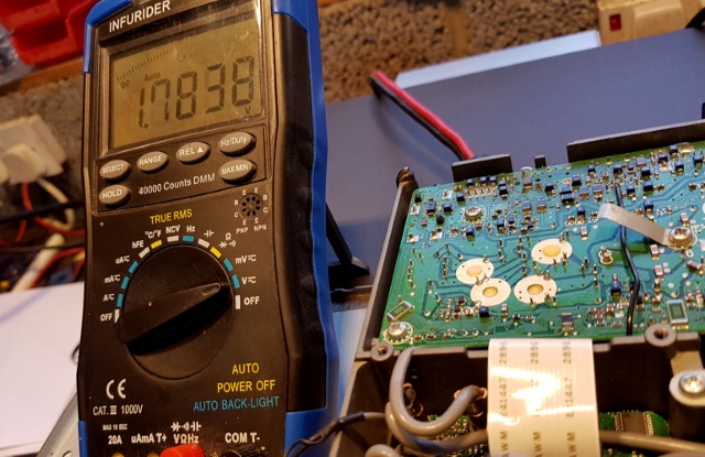 After years of reliable performance, a 26-year-old Icom 706MK2G exhibited an unusual deviation during FM transmission, with the actual frequency being 10kHz off from the displayed frequency. Additionally, the power meter showed a sharp dip during transmission. Upon investigation, it was discovered that the FM VCO voltage adjust variable had become dirty and sluggish over time. By adjusting the variable capacitor and cleaning it with switch cleaner, the issue was resolved, restoring stable power output and accurate frequency transmission.
 -
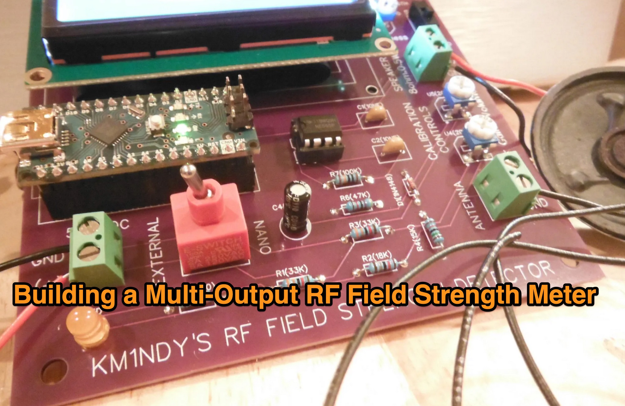 This article describes a DIY RF field strength meter project inspired by VK3YE's "The Squeakie" design. The device, built around a 555 timer IC and a 1N4148 diode, converts RF signal strength into audible tones with proportional pitch. The author enhanced the original design by adding volume control, LED indication, and digital readout capabilities using an Arduino Nano and LCD display. The completed project functions as a versatile RF detection tool, suitable for antenna testing and fox hunting, while offering multiple output methods: audio, visual, and digital measurement display.
 -
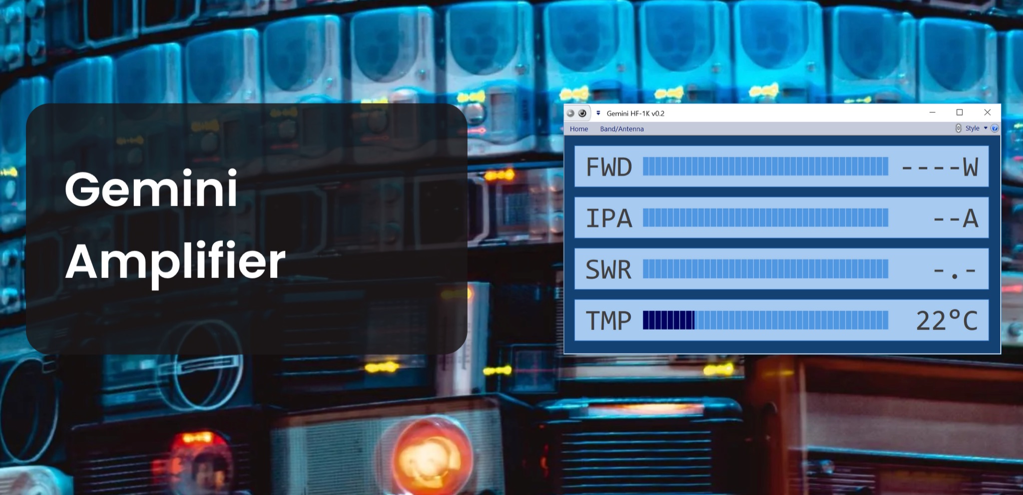 The Gemini Amplifier Remote Control software operates on Windows 7 and above, facilitating remote management of the Gemini HF-1K and DX-1200 amplifiers. Users connect via Ethernet, configuring the amplifier's IP address through the front panel. The software allows seamless band and antenna selection, saving settings for each band without requiring transmission. Integration with _OmniRig_ from Afreet Software, Inc. enables automatic band adjustments based on the radio's frequency changes. Users can configure serial or virtual serial connections, with tracking options accessible through the ribbon bar. The software supports speech functionality, enhancing accessibility for operators. Firmware updates, such as version 2.5Ee, introduce features like background datalogging and power output control, uploaded via FTP. Version 1.2.0 allows users to offload internal parameter data for support purposes. The firmware upload process requires the amplifier's IP address and port 21, taking approximately 90 seconds. Users are encouraged to upgrade to the latest firmware for improved performance and remote diagnostics.
 -
 The Alfa Alfa (AA) DX Group, established on March 1, 1974, in the Netherlands, is presented as the pioneering Dutch 27mc DX group. It details the group's historical significance, particularly its revolutionary use of the '000' club callsign (19AA000) which influenced international 11-meter group callsign structures. The resource outlines the group's re-establishment in 2024, inviting new active CB operators and _Short Wave Listeners_ (SWL) to join its ranks, emphasizing a free worldwide membership model. Membership requirements are specified, focusing on active participation with an assigned AA callsign. The group provides QSL card management services, with options for direct QSL requests requiring **3 USD** and a Self-Addressed Envelope, or **4 USD** via PayPal for expenses. It also mentions upcoming initiatives like an _AA DX Contest_ and an award program, with sections for certificates and plaques currently under construction. The site also lists useful CB resources, including an 11M DX Cluster and an 11M Callsign Database, and provides contact information for the founder, 19AA001 Mr. Theo, and the Worldwide QSL Manager, 178AA001 Mr. Emil, based in Bulgaria.
 -
 Optimizing on-air audio for SSB, DXing, and contesting operations is addressed through a range of specialized audio processing equipment. The offerings include multi-band equalizers, specifically 5-band, 8-band, 10-band, and 12-band units, some integrated with features such as compressors, echo effects, noise gates, and phase rotation capabilities. These devices are engineered to interface with common amateur radio transceivers, with explicit compatibility noted for models like the Yaesu FT-DX10, FT-DX101D, FT-1000MP, FT-DX5000, Collins HF-380, and Flex 6300, alongside analog S/P meters for Icom rigs. The product line focuses on enhancing microphone audio characteristics, supporting XLR dynamic microphones for improved signal clarity and presence. The manufacturer, DB6QW Electronics, emphasizes direct support and a 100% manufacturer's warranty, reflecting confidence in product quality and operational reliability. This resource details specific audio processing tools designed to refine the transmitted audio signal, providing operators with granular control over their voice characteristics for competitive and casual amateur radio communications.
 -
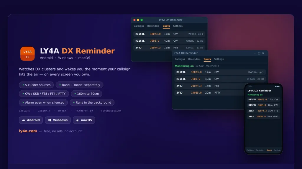 The LY4A DX Reminder application monitors five distinct DX cluster sources—DXScape, DXSummit, DXHeat, PSK Reporter, and Reverse Beacon—to alert amateur radio operators when a specific call sign appears. It supports a wide range of bands from 160 meters to 70 centimeters, including 60m, 6m, 2m, and 70cm, accommodating **CW**, SSB, FT8, FT4, and RTTY modes. The software operates in the background, checking clusters at user-defined intervals of 1, 5, 10, or 30 minutes, and persists across device restarts. Alarm functionality is robust, activating even if the mobile device is silenced, by utilizing the alarm channel and illuminating the locked screen. On desktop platforms, notifications remain active in the system tray. Users can directly manage alarms—stopping, snoozing, or deleting them—from the notification interface, enhancing operational flexibility during DX pursuits. Available in 15 languages, including English, Italian, German, and Spanish, the application is provided free of charge and without advertisements. It offers optional donation support for continued development. Installation instructions are detailed for Android, Windows 10/11 (64-bit), and macOS 12+, addressing common system security prompts for unsigned applications.
 -
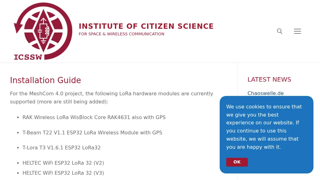 The resource provides a technical installation guide for _MeshCom 4.0_, an amateur radio mesh networking project utilizing LoRa hardware modules. It systematically covers the setup process for several supported devices, including the RAK Wireless LoRa WisBlock Core RAK4631, T-Beam T22 V1.1, T-Lora T3 V1.6.1, HELTEC WiFi ESP32 LoRa 32 (V2 and V3), HELTEC E290, ESP32 / E22 modules, and the T-deck from Lilygo. The guide specifies support for the **EU433** frequency band, ensuring amateur radio compatibility, and details the use of an online flash tool for ESP32 modules and an embedded drive for RAK modules. It further describes accessing the MeshCom 4.0 Dashboard and Map functionalities, crucial for network visualization and management. Firmware configuration for ESP32 modules is meticulously outlined, covering essential parameters such as setting callsigns, country codes, and gateway parameters via a serial console like PuTTY. Commands for activating gateway mode, setting internet IP addresses, and configuring WLAN SSID and password for modules with WLAN capability are provided, enabling modules to function as either clients or gateways within the MeshCom network.