Search results
Query: hf signal
Links: 174 | Categories: 6
-
 This project describes the construction of a W3HH (T2FD) antenna for HF bands (3-30 MHz). While less efficient than a tuned dipole, it offers broad frequency coverage with a maximum SWR of 3.4 and reduces QRM (noise) significantly. On the 80-meter band, it shows slightly weaker signals than a dipole but with improved signal-to-noise ratio. The design includes non-inductive resistors, a 13:1 balun, and a "frog ladder" transmission line. Though not a high-performance antenna, it is compact and versatile, making it ideal for wide-band HF communication. Article in French
 -
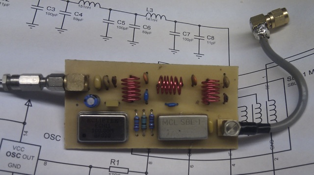 This article describes an HF upconverter for the FunCube Dongle Pro. Designed for radio amateurs, the converter extends reception capabilities to lower frequencies (0 Hz to 30 MHz) by mixing them with a higher oscillator frequency (100 MHz). This translates the desired signal into a range detectable by the FunCube Dongle (64 to 1,700 MHz). Key components include a double-balanced mixer and a low-pass filter to suppress unwanted signals. The project provides schematics, filter specifications, and design considerations for construction.
 -
 This PDF file provides detailed information on HF propagation for ham radio operators. It covers the principles of how radio signals travel over long distances, including factors that affect signal strength and propagation. The content is useful for hams looking to improve their understanding of radio communication and optimize their transmissions. Whether you're a beginner or an experienced operator, this resource offers valuable insights into HF propagation that can enhance your communication skills and efficiency on the airwaves.
 -
 Effective suppression of harmonics and parasitic radiation from HF transmitters is crucial, especially with the increasing sensitivity of VHF/UHF radio channels to interference. This project details a hybrid low-pass filter (LPF) designed to operate across the HF bands up to 51 MHz, making it suitable for 6-meter band operations while providing deep VHF/UHF suppression. The design addresses the challenge of modern interference landscapes, where even microvolt-level signals can disrupt wireless sensors and other simple VHF/UHF receivers. The filter utilizes a single elliptic link, combining high cutoff steepness with robust suppression in the hundreds of megahertz range. A key feature is the use of only two standard capacitor values, simplifying construction and component sourcing. The article provides a detailed schematic, performance characteristics, and _RFSim99_ model file, demonstrating a reflection coefficient S11 below 0.017 (VSWR < 1.03) across 1-51 MHz, ensuring minimal degradation to the antenna system. Construction notes include coil winding specifications and capacitor selection guidance, with recommendations for _FR-4_ assembly. Two capacitor sets are presented, with the first variant recommended for its lower RF current demands, keeping currents below 3 A at 1 kW passing power at 51 MHz. Fine-tuning involves adjusting frameless coils, with considerations for capacitor tolerance and high-frequency capacitance measurement accuracy.
 -
 Compare the efficiency of two HF (or VHF) antennas by simultaneously transmitting FT8 on nearly the same frequency and analyzing PSKReporter SNR data. Determine the effectiveness of your new antenna compared to the old one in dB, to several decimal places. Run FT8 on two transmitters with different call signs and equal power, connected to each antenna. AntennaCompare analyzes global signal reports, isolating antenna performance.
 -
 This project details the development of a modular direct conversion (DC) receiver designed for experimental flexibility in amateur radio and HF signal listening. The mainframe integrates a diplexer, DBM, and AF amplifier, supporting interchangeable local oscillator and antenna filtering setups. A tunable passive HF preselector complements QRP Labs bandpass filters for enhanced signal reception. Utilizing a NanoVNA for precise tuning, the receiver achieves improved signal-to-noise ratios across amateur and non-amateur bands, making it a versatile platform for further RF experimentation.
 -
 This project details an automatic roger beep circuit for VHF/UHF contests. Built around a Microchip PIC microcontroller, the design detects PTT (Push-To-Talk) activation and generates a brief tone upon release, mimicking a "roger beep" to signal the end of transmission. The circuit utilizes readily available components and includes downloadable resources for PCB layout and firmware.
 -
 Operating amateur radio repeaters involves understanding frequency offsets, CTCSS tones, and the basic signal flow through a repeater system. This resource details the fundamental concepts of repeater operation, including the distinction between input and output frequencies, the role of **CTCSS (Continuous Tone-Coded Squelch System)** for access, and the typical frequency bands utilized for local communication. It clarifies terms such as "simplex" versus "duplex" operation and provides a diagram illustrating the signal path from a handheld transceiver to a repeater and back to another station, emphasizing the range extension repeaters offer. The article further explains practical aspects like identifying a repeater's offset (e.g., +600 kHz for 2-meter band) and the necessity of programming the correct tone. It compares the operational benefits of using repeaters for local communication over direct simplex contacts, highlighting how repeaters overcome line-of-sight limitations. The content is structured to assist new licensees in confidently making their first repeater contacts, providing a foundational understanding of how these critical infrastructure components facilitate wider area coverage for VHF/UHF amateur radio.
 -
 The Acom 1500 HF+6M Linear Amplifier is a high-quality and user-friendly amplifier that provides excellent performance and reliability. G6NHU, who previously owned an Acom 1000, upgraded to the Acom 1500 after nine years and has been using it for about eighteen months. Key features highlighted include the ability to connect three antennas internally, straightforward tuning process, robust construction that can handle high SWR, quiet operation, fast and quiet switching for efficient CW operation, and clean output signal even when driven hard. G6NHU highly recommends the Acom 1500 and states they would not hesitate to purchase another one in the future.
 -
 An FT-817 ceased transmission on the VHF 2m band, despite the other HF, UHF, and 50 MHz bands operating correctly. Suspecting an excess of input signal during FT-8 mode transmission, they conducted measurements with an oscilloscope, revealing a burnt-out PIN diode, identified as D3003, type HSU277, on the PA unit board. Following the replacement of this surface-mounted diode, their FT-817 resumed operation on the 144 MHz band.
 -
 This project involved designing a 7-pole Chebychev broadcast band filter to address severe interference issues caused by a new horizontal loop antenna on the KN-Q7A transceiver. The interference overwhelmed the transceiver’s front end, so a custom filter with a 3.5 MHz cutoff was built using silver mica capacitors and type 6 T130 toroidal cores. Encased in a diecast box with SO239 sockets, the filter blocks strong signals from the broadcast band, achieving over 100 dB attenuation. Tested up to 100W, it reduces interference effectively while maintaining low insertion loss across HF bands.
 -
 Ham radio communication in the VHF and UHF bands, which was previously dominated by analog Frequency Modulation (FM), is increasingly incorporating Digital Voice (DV) modes. DV transceivers digitize audio and offer benefits like as signal integrity, encoded caller ID, and bandwidth savings. Today D-STAR, DMR and Yaesu System Fusion (YSF) are popular DV formats, each with its own set of features but mainly incompatible with the others. Internet access with Voice Over Internet Protocol (VoIP) expands DV communication worldwide. Repeaters and personal hotspots expand DV capabilities, enabling seamless worldwide connections. However, implementing DV frequently necessitates learning new technologies and negotiating network complexity.
 -
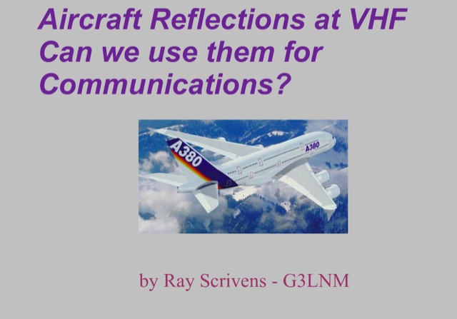 This PDF presentation explores using aircraft reflections for VHF communication. It explores the characteristics of reflected signals, including how they cause fading and vary in frequency due to aircraft movement. The feasibility of using such signals for communication is then examined. The presentation highlights challenges like requiring very narrow filters and strong frequency stability. It explores Slow-Feld, a slow version of Hellschreiber, as a potential modulation mode due to its tolerance for weak signals and frequency variations. While successful communication via aircraft reflections has been achieved, the data rate was slow and intermittent. The potential for communication over long distances, especially with busy air traffic, is discussed.
 -
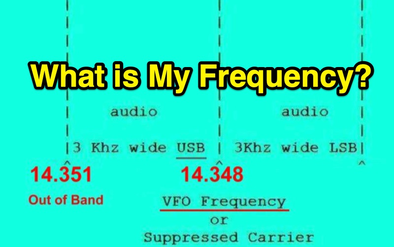 Single Sideband (SSB) operation requires careful attention to the relationship between a radio's displayed frequency (suppressed carrier) and the actual 3 kHz wide audio signal. This resource clarifies how Upper Sideband (USB) and Lower Sideband (LSB) signals occupy spectrum above or below the indicated frequency, respectively. It provides practical examples for General Class operators on the **20m** and **40m** bands, such as setting a VFO to 14.226 MHz for USB on 20m or 7.178 MHz for LSB on 40m, to maintain a safe margin from band edges. The resource emphasizes the critical importance of staying within allocated band limits to prevent out-of-band emissions, particularly when operating close to band edges. It includes relevant excerpts from **FCC Regulation Part 97**, specifically section 97.307, which details emission standards, necessary bandwidth, and spurious emission attenuation requirements. The text explains that unused sidebands are considered spurious emissions and notes that modern HF equipment typically exceeds the 43 dB spurious emission reduction standard, often achieving 60 dB or more.
 -
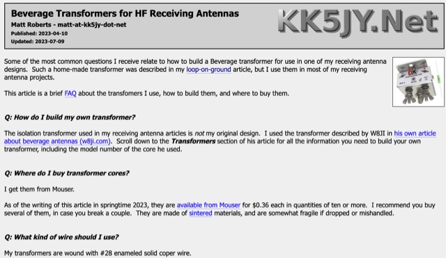 This FAQ covers building and buying transformers for loop-on-ground and Beverage antennas. Building one uses ferrite cores and thin wire. Buying is an option, with the DX Engineering BFS-1 being recommended. These transformers isolate the antenna from the cable to prevent unwanted signal pickup.
 -
 The article discusses the construction of a UHF band-stop stub filter to protect an APRS receiver from potential damage during a balloon launch. The author, who communicates using a 441 MHz transmitter, needed to ensure that the RTL-SDR dongle receiving at 144 MHz wouldn't be damaged by the transmissions. The solution involved creating a quarter-wavelength open stub filter using coaxial cable, which attenuates the 441 MHz signal while allowing the 144 MHz signal to pass through. The filter's design is based on the principles of constructive and destructive interference, with careful measurement and trimming to achieve the desired frequency response. The final filter provided 34.8 dB of insertion loss at 441 MHz and minimal loss at 144 MHz, effectively protecting the receiver.
 -
 The Olivia digital mode, a **Multi-Frequency Shift Keying (MFSK)** radioteletype protocol, is specifically engineered for robust communication under difficult propagation conditions on shortwave radio bands from 3 MHz to 30 MHz. Developed by Pawel Jalocha in 2003, Olivia signals can be decoded even when the noise amplitude exceeds the digital signal by over ten times, making it highly effective for transmitting ASCII characters across noisy channels with significant fading and propagation phasing. Early on-the-air tests by Fred OH/DK4ZC and Les VK2DSG on the Europe-Australia 20-meter path demonstrated intercontinental contacts with as little as one-watt RF power under favorable conditions. Common Olivia modes are designated as X/Y, where X represents the number of tones and Y is the bandwidth in Hertz, with examples including 8/250, 16/500, and 32/1000. The resource clarifies that Olivia, unlike some other digital modes, produces a constant envelope, allowing RF power amplifiers to achieve greater conversion efficiencies and making it less prone to non-linearity. Operators are advised that **Automatic Level Control (ALC)** can be set higher than no meter movement for MFSK modulation, as long as it's not driven past its high limit, contrary to common misinformation about other digital modes. The Olivia community encourages voluntary channelization on suggested calling frequencies, such as 14.0725 MHz for 8/250, to facilitate initial contacts, especially for signals below the noise floor. The Olivia Digital DXers Club provides links to Groups.io, Facebook, and Discord for community engagement and offers details on QSO parties.
 -
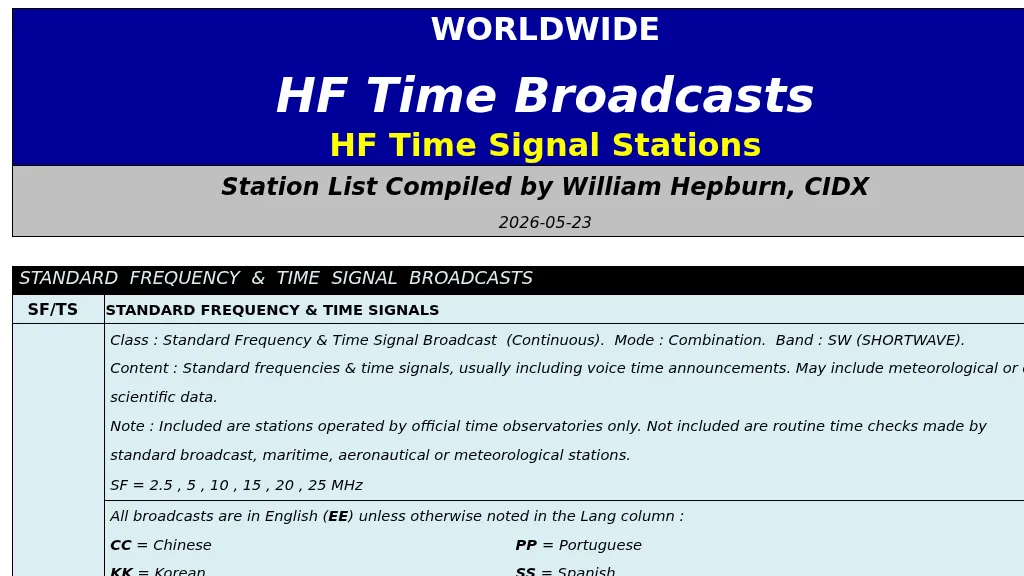 The resource details HF time broadcast stations, categorizing them into "Standard Frequency & Time Signal Broadcast" and "Time Signal Broadcast" types. Standard Frequency & Time Signal Broadcasts, like those on **2.5 MHz** and **5 MHz**, originate from official time observatories and offer continuous standard frequencies, time signals, and often voice announcements, potentially including meteorological data. These stations operate in the SW band. Time Signal Broadcasts also provide continuous time signals, typically with voice announcements, but without the strict observatory origin requirement. The list includes specific frequencies such as 3.33 MHz, 4.996 MHz, 7.85 MHz, 9.996 MHz, 14.67 MHz, 14.996 MHz, 15.006 MHz, and 20 MHz, alongside the primary standard frequencies. Each entry specifies the station's ID time, call sign, geographic coordinates, and operational notes, including languages like _English_, Chinese, Portuguese, Korean, and Spanish. Some entries also indicate decommissioning dates, such as the station on 3.33 MHz scheduled for 2026-06-22.
 -
 Twenty 1-watt carbon film resistors are configured in parallel to construct a 50-ohm **dummy load** for amateur radio applications. The design incorporates a heatsink for thermal dissipation and an **SO-239 connector** for RF input, making it suitable for QRP operations. This budget-friendly project details component selection, soldering techniques, and mounting procedures, achieving a continuous power rating of 10 watts and intermittent handling of up to 100 watts across HF and VHF frequency ranges. The resource provides a step-by-step guide for assembly. This construction offers an economical solution for essential shack tasks such as antenna tuning, transmitter testing, and SWR meter calibration without radiating an RF signal. The utilization of readily available components significantly reduces the overall build cost compared to commercial alternatives, providing radio amateurs with a functional and reliable test accessory. While specific VSWR measurements are not provided, the design prioritizes practical utility for low-power transceiver diagnostics and general RF experimentation.
 -
 Operating amateur radio satellites presents unique challenges, particularly concerning antenna design and signal propagation. Juan Antonio Fernández Montaña, EA4CYQ, recounts his three-year journey into satellite communication, starting with initial guidance from EB4DKA. His early experiments involved a portable 1/4 wave VHF antenna with four 1/4 wave ground planes, designed for hand-held use to adjust polarity. This setup, paired with an FT-3000M transceiver, allowed full-duplex operation on **VHF** transmit and **UHF** receive, proving effective for early contacts on satellites like AO27, UO14, and SO35. EA4CYQ's experience highlights the critical role of coaxial cable loss and antenna polarization. After encountering significant signal degradation with longer RG213 runs, he experimented with a 1/2 inch commercial cable, noting improved reception but persistent fading due to varying satellite polarities. This led to the construction of an **Eggbeater II** antenna, an omnidirectional UHF design offering horizontal polarization at the horizon and circular right polarization at higher elevation angles. Subsequent modifications resulted in the directional **TPM2** antenna, which provided sufficient gain for LEO satellites with a wide 30-degree lobe, enabling consistent contacts from his home station. The article concludes with practical insights on the performance of the Eggbeater II for both UHF and VHF, and the TPM2 for UHF, emphasizing their utility for portable and fixed operations. EA4CYQ's journey underscores the iterative process of antenna development and the importance of adapting designs to overcome real-world propagation challenges in satellite communications.
 -
 Assessing the ICOM IC-R9000 communications receiver, this review details its operational parameters and user experience for radio enthusiasts. Introduced in 1985, the IC-R9000 covers a broad frequency spectrum from 0.1 MHz to 1999.8 MHz, making it suitable for a wide array of listening activities from medium wave (MW) to VHF/UHF. Key performance metrics include a dynamic range of **102 dB** with the narrow SSB filter, crucial for discerning weak signals in crowded bands, and its substantial physical dimensions of 424 x 150 x 365 mm and 20 kg weight. The receiver's architecture supports various modes, though it notably lacks synchronous detection, a feature often desired for improved AM reception under fading conditions. It incorporates 1000 memory channels and robust scanning capabilities, facilitating efficient monitoring across its extensive frequency range. This analysis provides insights into the IC-R9000's capabilities and limitations, offering a historical perspective on a significant piece of amateur radio and shortwave listening hardware.
 -
 This online project documentation details the construction of a hands-free microphone interface unit designed for _mobile_ amateur radio operation. The curriculum covers the integration of electret microphone elements with amateur radio transceivers, specifically addressing **VHF** band communication. It outlines the circuitry for a switch box that provides an interface between various radio models and microphone types. The guide specifies the inclusion of a **1750 Hz** tone-burst generator for accessing amateur radio repeaters, an operational protocol for many VHF systems. Design considerations include the reduction of ambient vehicle noise through an adjustable audio input level control. The project provides schematics and wiring diagrams for connecting the interface unit to specific amateur radio transceivers, including the Yaesu FT-817. It addresses the selection and adaptation of readily available electret microphone and earpiece assemblies, initially sourced from mobile phone accessories, and later from dedicated headset units. The design incorporates a control mechanism for radio functions, enabling hands-free operation during _mobile_ excursions. Circuit details cover power supply considerations for the electret microphone and signal routing for both transmit audio and received audio monitoring. The documentation specifies component selection for the switch box, ensuring compatibility with common amateur radio microphone input impedances and output levels. This includes considerations for PTT line switching and audio path isolation. DXZone Focus: Online Project Documentation | Hands-Free Mobile Microphone Interface | Electret Microphone Integration | 1750 Hz Tone-Burst Generation
 -
 Early 20th-century transatlantic wireless communication efforts involved distinct technical approaches by Reginald Fessenden and Guglielmo Marconi. Marconi's systems, operational until approximately 1912, primarily utilized _spark technology_ for wireless telegraphy, facilitating Morse code communication between ships and across oceans. His Poldhu station in December 1901 radiated signals in the MF band around 850 kHz, later evolving to 272 kHz in October 1902, and eventually 45 kHz by late 1907 with increasingly larger antenna structures like the pyramidal monopole and capacitive top-loaded arrays. Fessenden, conversely, focused on _continuous wave transmission_ for wireless telephony, recognizing its necessity for speech. His transatlantic experiments in 1906 employed synchronous rotary-spark-gap transmitters and 420-foot umbrella top-loaded antennas at Brant Rock, MA, and Machrihanish, Scotland, tuned to approximately 80 kHz. Fessenden later utilized the _Alexanderson HF alternator_ at 75 kHz by late 1906 for pure CW transmission, integrating a carbon microphone for amplitude modulation. Receiver technology also differed, with Marconi initially relying on untuned coherer-type detectors, later developing the magnetic detector in 1902, while Fessenden's CW approach necessitated more advanced detection methods.
 -
 Demonstrates the construction of an active loop converter specifically designed for the Low Frequency (LF) bands, addressing common localized noise interference in LF reception. The design integrates a sharply tuned circuit and a tuned loop antenna, utilizing the loop as the sole tuned inductive element. By applying positive feedback, the converter significantly increases the loop's effective Q, achieving factors between 1000 and 2000, which sharpens tuning and reduces noise. The circuit employs an _NE602_ mixer stage, feeding its output to an HF receiver, with a crystal-locked local oscillator at 4 MHz. A 20-turn, 0.8-meter square loop antenna with 500 uH inductance is detailed, connected via 2 meters of figure 8 flex cable. The converter offers three selectable frequency bands: 195-490 kHz, 150-220 kHz (including the New Zealand amateur band), and 128-160 kHz (covering the European amateur band). Performance measurements indicate an effective 3dB bandwidth of approximately 100 to 200 hertz at 200 kHz. The article provides insights into component selection, including an _LF353_ op-amp and a trifilar wound transformer on a ferrite core. Sensitivity figures are presented, showing 7.5 uV of converted output per 1 uV/meter signal strength into a 50-ohm load, or 37.5 uV into an _FRG7_ receiver, highlighting its capability to extract weak signals from noise.