Search results
Query: yagi antenna
Links: 379 | Categories: 18
Categories
- Antennas > 20M > 20 meter Yagi antennas
- Antennas > 40M > 40 meter Yagi Antennas
- Antennas > 6M > 6 meter Yagi Antennas
- Radio Equipment > HF YAGI Antennas
- Manufacturers > Antennas > VHF UHF Microwave > Yagi Antennas
- Manufacturers > Antennas > HF > Yagi Antennas
- Antennas > Yagi
- Antennas > 15M
- Antennas > 17M
- Antennas > 20M
- Antennas > 23cm
- Antennas > 70cm
- Radio Equipment > HF YAGI Antennas > Cushcraft A3S
- Radio Equipment > HF YAGI Antennas > Cushcraft MA5B
- Radio Equipment > HF YAGI Antennas > Cushcraft X7
- Manufacturers > Antennas > HF
- Radio Equipment > HF YAGI Antennas > Hy-Gain TH3JR
- Antennas > Satellite
-
-
 Yagi-logper is a linux GPL program to model a Yagi or Log-periodic antennas with horizontal cylindrical dipoles.
 -
 Designers and manufacturers of radio Frequency antennas. HF - 3000 MHz TET Emtron HF Yagis, Antennas for Wireless applications, Marine antennas, Land mobile, Mobile antennas.
 -
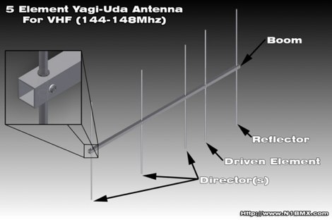 A project for a home made 5 element yagi-uda antenna for 2 meters, covering 144-148 MHz band by N1BMX
 -
 The Moxon Beam, introduced by L. Moxon (G6XN), is a compact 2-element Yagi featuring a radiator and reflector with reduced dimensions, approximately 75% the size of a full-size beam. This design utilizes bent element ends for capacitive loading, which is superior to inductive loading with coils, resulting in greater bandwidth and lower losses. DK7ZB details that while the gain is slightly lower (0.5-0.7 dB) than a full-size beam, the _Moxon_ offers an exceptional front-to-back (F/B) ratio of 30 dB or more on its design frequency, surpassing other 2-element beams. The article provides specific dimensions for building wire _Moxon_ antennas for bands from 30m down to 10m, and also mentions a 2-m-Moxon. Construction guidance includes using fishing rods for lightweight spreaders and an aluminum tubing spider for support. The resource highlights the utility of _Moxgen_ by AC6LA, a freeware program that simplifies Moxon beam design and generates EZNEC output files for further analysis and tapering modifications. DK7ZB emphasizes that the design frequency should be set at approximately one-third from the band's beginning to optimize SWR performance, as SWR tends to rise more significantly below the design frequency. The bandwidth for SWR < 1.5 is noted as sufficient for ranges like 28.0-28.7 MHz and 21.0-21.45 MHz when constructed with aluminum tubes, though wire beams exhibit a narrower bandwidth.
 -
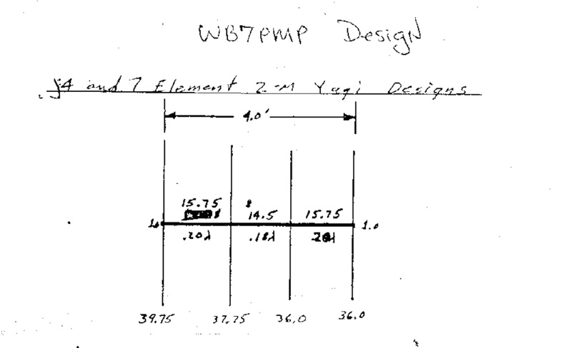 Original drawing and design of a 4 and 7 elements yagi antenna for 50 Mhz
 -
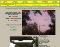 Collection of different techniques to homebrew PVC yagi antennas, including elements assembling, baluns and chokes, radiator box tips and tricks by dk7zb
 -
 This document details the design and construction of a Vinecom 6N4 dual-band Yagi antenna for the 50MHz (6-meter) and 70MHz (4-meter) amateur radio bands. The antenna features 9 total elements (4 elements for 50MHz, 5 elements for 70MHz) on a 4.236-meter aluminum boom. Computer simulations using MMANA software predict 7.21 dBd gain on both bands with front-to-back ratios of 16.01dB (6m) and 15.37dB (4m). The design uses 12.7mm diameter elements mounted on a 32mm square boom, weighing 5.7kg total. Practical measurements with an MFJ-269 analyzer confirmed good SWR performance across both bands after element length adjustments.
 -

-
 Cheap UHF antenna plans for 2 meters and up including 421 1296 and 902 Mhz
 -
 Homebrew a compact yagi antenna for 14 Mhz suitable for those with small plots based on a design by AB4GX
 -
-
 The GW3YDX Super Moxon antenna design improves upon the standard Moxon Rectangle by incorporating additional directors in a rectangular configuration, yielding enhanced directivity and gain. For the 6m version, modeling with 4NEC2 and EZNEC+ indicated a 3dB gain increase and a 26.5dB front-to-back ratio, with VSWR below 1.5:1 between 50.0 and 50.3MHz when optimized for 50.1MHz. This design achieves a narrower -3dB power point beamwidth of 60° compared to the original Moxon's 80°, contributing to better QRM rejection. The boom length for the enhanced design is just under 2m, approximately double the original Moxon's, with no increase in wingspan. Construction details include tubing lengths for 6m, 4m, and 2m versions, with specific dimensions provided for elements A through M, measured to tubing centers. For instance, the 6m version uses a 2160mm element A and a 2140mm element H. The design maintains a 50-ohm feed impedance, with practical models showing VSWR plots consistent with simulations after minor adjustments to driven element lengths. The article also references Moxgen software for initial Moxon parameter calculation and NEC/EZNEC model generation. The 2m Super Moxon version measures approximately 30" x 25", demonstrating the compact nature of the design across different VHF bands. The article highlights the antenna's performance in real-world DX contacts on 6m, achieving contacts with over 80 stations in the USA from a modest QTH.
 -
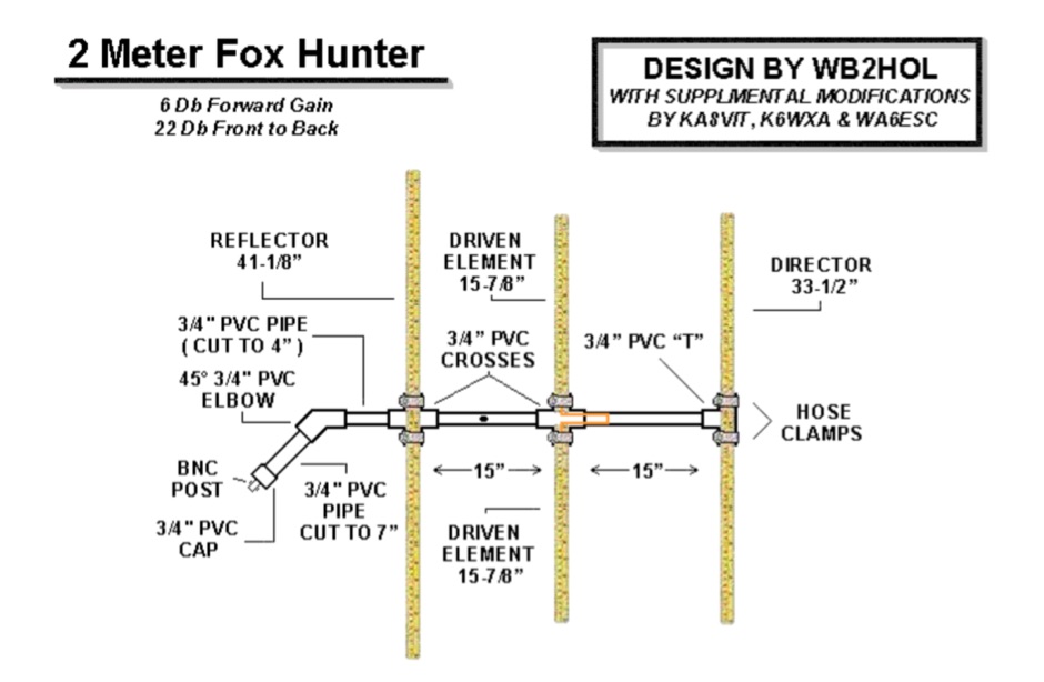 A home made yagi antenna featuring 6db forward gain and 22 Db front back
 -
-
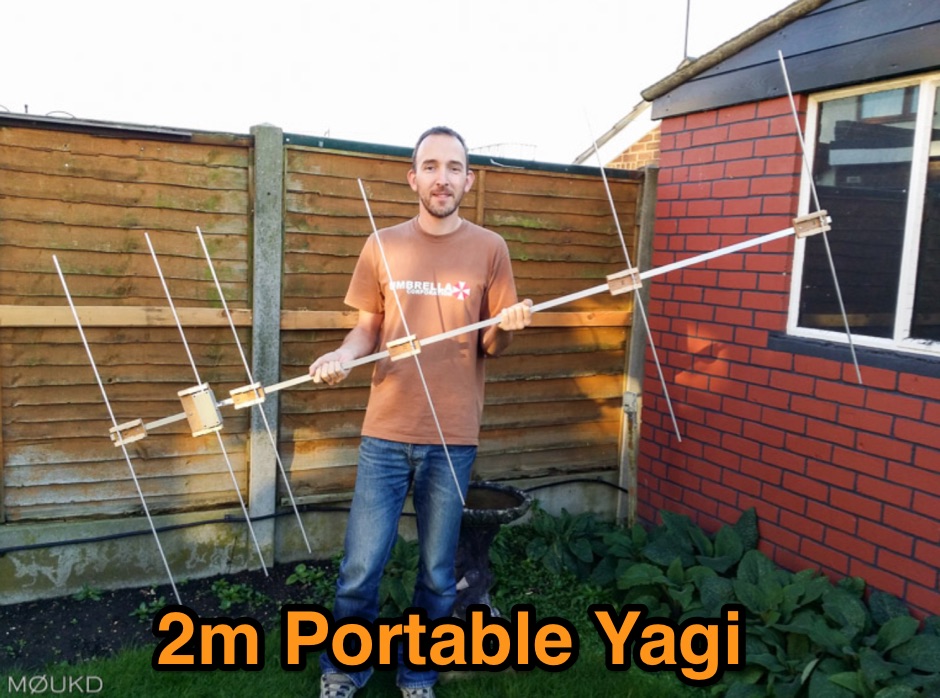 Building a 2 metre 144MHz VHF Yagi beam antenna, designed for portable use.
 -
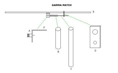 how to make a gamma match for a antenna. The Gamma match is the most used matching device used for yagi beams.
 -
-
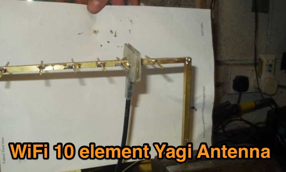 A DIY project of a WiFi 10 elements Yagi antenna
 -
 A 70cm and 2m 6 elements yagi antenna plan based on the IEEE Transactions on Antennas and Propagation
 -
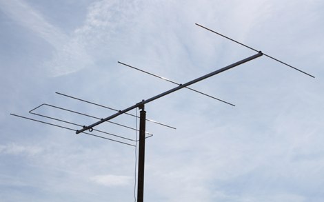 A Loop Fed Array Yagi antenna for 50 MHz featuring 11 dBi gain and 23 f/b ratio. In this excellent page the author even includes a detailed drawing in DWG format, with element lenght and spacing measures, in a separa file a full list of material list needed to build this yagi antenna including source and price, the EZnec file for this antenna plan, and a lot of pictures of this LFA Yagi for 50 Mhz. A ten page PDF file containing all infos, is also available to download.
 -
 The resource details the construction of a 3-element Yagi antenna specifically designed for the 6-meter band, providing coverage across 50-54 MHz. This antenna design, originally featured in _QST_ August 2007, emphasizes a short boom configuration while maintaining a wideband response. Key specifications include a 50 Ohm SWR of less than 2:1 across the entire band, achieved through specific element lengths and spacing. The design utilizes aluminum tubing for elements and boom, with detailed dimensions provided for the driven element, director, and reflector. Performance characteristics indicate a forward gain of approximately 7.5 dBi and a front-to-back ratio of 18 dB at 50.125 MHz, according to _NEC2_ modeling. The antenna's compact size, with a boom length of 1.83 meters (6 feet), makes it suitable for portable operations or installations with limited space. Construction involves standard amateur radio workshop tools and materials, with a gamma match for impedance transformation to 50 Ohms. The design prioritizes ease of construction and repeatable performance for the 6-meter enthusiast.
 -
 The Yagi-Uda antenna, information on basic design, project and measure of Yagi-Uda antenna, include free repository/sample of beam antenna.
 -
 The Cushcraft X7 Tribander assembly and installation manual (P/N 951470, 12/97) provides comprehensive instructions for constructing this 20-15-10 meter seven-element beam antenna. It details the sequential assembly of boom sections, individual elements, and the feed system, including the _MNX7 Matching Network_. The document emphasizes critical safety precautions regarding power lines and RF exposure, alongside recommendations for proper antenna system planning and grounding. Key sections cover verification of parts, detailed boom assembly using specific aluminum tubing (e.g., BA, BB, BC, BD, BE) and brackets, and element construction with various aluminum tube sections (e.g., EA, EB, EC, ED, EE, EF) and traps like the _15 Meter Director Trap_ (TB) and _10 Meter Director Trap_ (T9). It also specifies the use of _NOALOX® conductive lubricant_ for telescoping sections and hardware to prevent galling. The manual outlines the feed system assembly, which includes feed-straps (FL1, FL2, FL3), tuning-tube insulators, and the matching network. It also mentions the optional X740 40-meter add-on kit, which requires a separate coax feed. Detailed diagrams and parts lists with metric equivalents facilitate accurate construction and ensure the antenna performs as specified.
 -
 Demonstrates the construction of a 144 MHz turnstile antenna, detailing its design for omnidirectional, horizontally polarized VHF operation. The resource outlines the physical dimensions and materials required, including specific lengths for the radiating elements and the use of _RG-58_ coaxial cable for phasing. It covers the assembly process, emphasizing the critical spacing and connection points to achieve the desired radiation pattern and impedance matching for the _2-meter band_. The article presents measured _SWR_ performance across the 144-146 MHz segment, showing a low SWR of 1.2:1 at 144.5 MHz, which is suitable for general VHF use. It compares the turnstile's performance to a 9-element Yagi, noting the turnstile's advantage in providing consistent signal strength from all directions without requiring a rotator. Practical application for local FM simplex and repeater operations is implied, offering a simple yet effective antenna solution for fixed or portable stations.
 -
 Raising large Yagi antennas can be a challenging project. A trolley system will make the job a lot easier
 -
 A 4 element addition for 10m to an existing 4 element yagi (ZX antennas)
 -
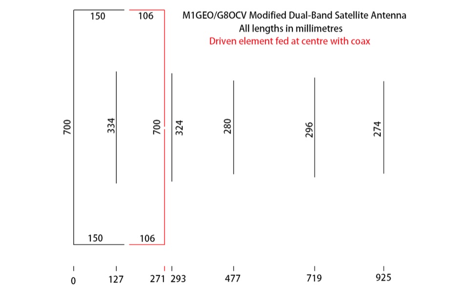 The antenna is a VHF side is a 2m moxon, tuned on 145.825 MHz. The driven element of the moxon couples to a driven element for a 5 element 70cms Yagi, tuned on 436.5 MHz.
 -
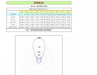 This is a plan for a 10 elements yagi antenna for 50 mhz
 -
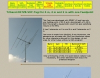 Triband DK7ZB VHF Yagi antenna for 6 m, 4 m and 2 m with a single feedpoint
 -
 The _Italian VHF Beacons_ resource provides a detailed listing of active and QRT amateur radio beacons operating across VHF, UHF, and SHF bands within Italy. Each entry specifies the beacon's callsign (e.g., IQ1SP/B), operating frequency (e.g., 144.411 MHz), QTH locator (e.g., JN44VC), effective radiated power (ERP) in watts, and antenna configuration (e.g., Big Wheel, 4x Dipole, Yagi). This data is crucial for radio amateurs involved in propagation studies, equipment testing, and long-distance (DX) communication on these higher frequency bands, offering fixed signal sources for monitoring. This compilation, last updated in October 2005, serves as a historical snapshot of Italian beacon activity. For instance, it lists several 144 MHz beacons with ERPs ranging from **0.1W** to **10W**, and higher frequency beacons such as I8EMG/B on 1296.880 MHz and I3EME/B on 24192.132 MHz. The inclusion of QRT (Quiet Radio Teletype) status for many entries indicates the dynamic nature of beacon operations over time. Users can utilize this information to identify potential signal sources for band openings or to calibrate their receiving equipment against known transmissions.
 -
 The original project of a dual band yagi antenna for 50 and 70 mhz, published on dubus 2/2007 by YU7EF
 -
-
 This project details the construction of a **full-sized 40-meter vertical antenna**, born from a renewed interest in 7 MHz operation and a desire for improved effectiveness over simple dipoles. The author, K5DKZ, initially focused on VHF experimentation, which provided an inventory of aluminum tubing and fiberglass spreaders for this endeavor. Before this vertical, K5DKZ utilized an 80/40 meter inverted-vee trap dipole and a 40-meter broadband dipole, but now primarily uses a pair of full-sized, phased, quarter-wave verticals spaced 35 feet apart for serious 40-meter work. The construction involves a base-heavy design for stability, using a 44.5-inch section of 1-1/4 inch steel TV mast driven into 1-3/8 inch aluminum tubing, insulated by a 105-inch section of Schedule 40 PVC pipe. The assembly reaches 31 feet, close to the 32 feet required for a quarter-wavelength on 40 meters, with fine-tuning achieved by winding wire onto a fiberglass spreader. The design is explicitly presented as a foundation for a two-element 40-meter Yagi beam, outlining modifications like substituting aluminum for steel in the base and using an inductive hairpin match for the driven element. The article also discusses tuning considerations for a large 40-meter beam, noting the 100 to 200 kHz upward frequency shift when raised, and suggesting methods for installation on a tower. The author emphasizes the cost-effectiveness and good performance of the monopole approach, especially when multiple verticals are needed.
 -
 VE3CVG 222 MHz (1.25m) 6 element plumber's delight yagi antenna
 -
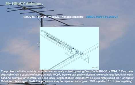 A page by 9A7PJT dedicated to HB9CV yagi antennas includes link to the HB9CV calculator program and some interesting plans
 -
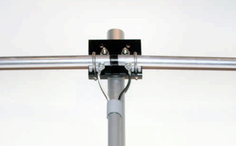 Design and build an 6 m dipole antenna from aluminum, tubing, that resembles the active element of a yagi beam antenna.
 -
 The design and feeding of driven elements for VHF/UHF Yagi antennas , modeling, observations and some case studies by Graham Daubney F/G8MBI
 -
 Antenna dimension, diagram and simulation of the ZX Antennen ZX 6-6 Yagi for VHF UHF by DF9CY
 -
-
 Demonstrates the adaptation and construction of a 7-element DK7ZB Yagi antenna for the 4-meter band (70 MHz), utilizing components from a defunct 2-meter CUE DEE Yagi. The resource details the modifications made to the original DK7ZB design to fit the shorter CUE DEE boom length, specifically adjusting element lengths for 6mm rod elements while reusing existing mounting holes for the reflector and last director. It provides precise element lengths for the reflector, dipole (12mm aluminum tube), and five directors, along with a note on cutting elements for transport. The article includes a 4NEC2 simulation file for performance analysis and an SWR plot, confirming the antenna's electrical characteristics. It also specifies the calculation for the quarter-wavelength matching cable using SAT752F coaxial cable, resulting in a 909mm length. Practical application is shown with the finished antenna in operation at JO20XC, listing several activated Maidenhead squares such as JO56PA and JP40KS, validating its effectiveness for portable 70 MHz operations.
 -
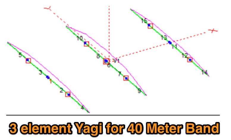 An homebrew project for a 3 element coil-loaded Yagi beam antenna for 40 Meter band
 -
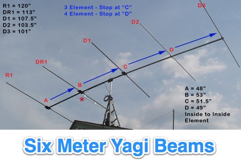
 A 5 elements homemade DK7ZB yagi antenna for 4 meters band based on a 50MHz TONNA
 -
 Article describing how to homebrew a yagi antenna for 50 MHz, includes plans for a four and five elements yagi beam and details how how match impedence with a gamma match
 -
 High quality VHF/UHF Yagi (directional) antennas
 -
 The 10-minute, 25-second video demonstrates making a QSO via the VO-52 amateur radio satellite, focusing on real-time Doppler shift correction. It features Simon, 2E0HTS, operating a Yaesu FT-847 transceiver and a homebrew dual-band Yagi antenna, specifically a 10-element 435 MHz Yagi for uplink and an IO Loop for 145 MHz downlink. The video visually details the operator's technique for continuously adjusting the uplink frequency to compensate for the satellite's changing velocity relative to the ground station, a critical aspect of successful satellite communication. The demonstration highlights the practical application of Doppler compensation, showing the operator tuning the transmit frequency to maintain a stable received signal from the satellite. This approach contrasts with systems employing automatic Doppler correction or full-duplex operation, providing insight into manual frequency management for satellite passes. The video serves as a direct, observational guide for hams interested in LEO satellite operations, particularly those using non-tracking, manually tuned setups.
 -
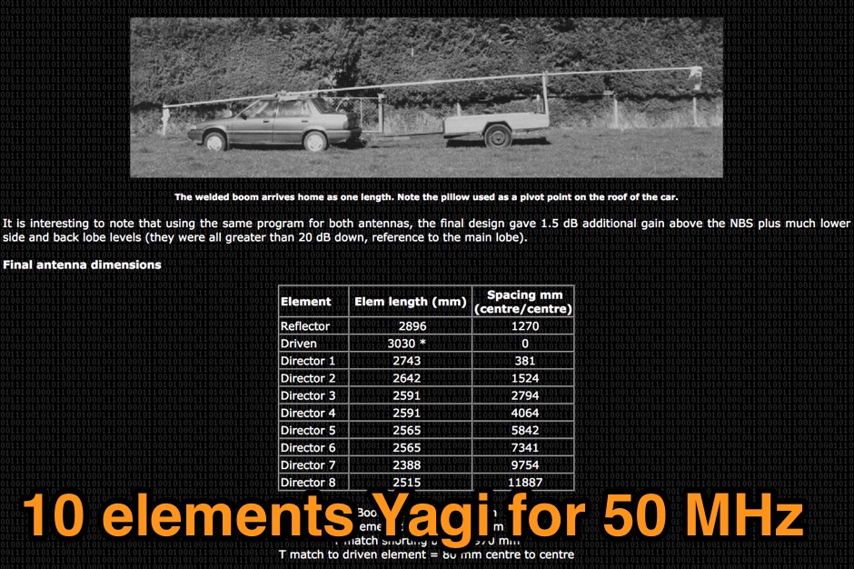 A homemade 10 element Yagi Beam Antenna for 50 Mhz by Rod Mackintosh, a NBS Yagi on a 13.2 metre boom.
 -
-
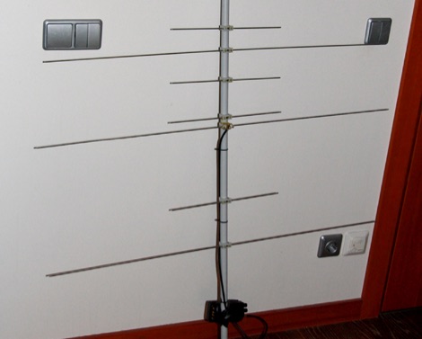 A VHF UHF handheld antenna suitable for satellite operation by LY3H include antenna plan with dimensions and pictures.
 -
 Ground Plane - 1/4 wave vertical, J-Pole, 3 Element Yagi Beam and simple antenna supports