Search results
Query: loop am
Links: 216 | Categories: 6
-
 This presentation on antennas is a practical guide for amateur radio operators. The key takeaway is that the best antenna for your station depends on your constraints and goals. There is no magic solution and buying a wire antenna is not recommended as it might be expensive and not as effective. The presentation covers different antenna types including dipoles, verticals, Yagis and loop antennas. Important factors to consider when choosing an antenna include SWR, feeder types, and whether you need a balun. The author emphasizes that ATUs don’t improve a poor antenna and advises against obsessing over SWR readings.
 -
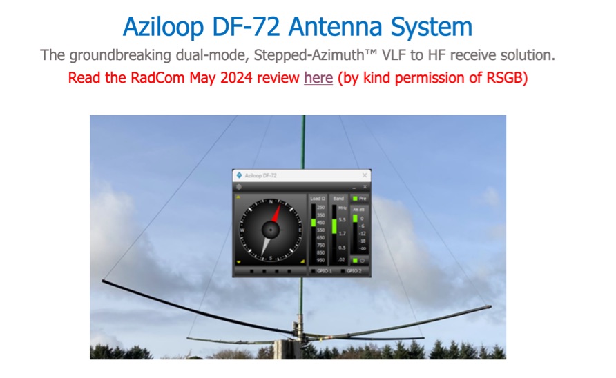 The Aziloop DF-72 antenna system provides 72 K9AY headings and 36 loop axes, allowing for rapid switching in 60 ms. It integrates a switchable 18 dB preamp, a 4-step attenuator (0-18 dB), and four 7-pole preselection filters to optimize receiver performance. The K9AY load is adjustable from 250 Ohm to 950 Ohm in 50 Ohm increments, offering flexibility for various receiving conditions. Control is managed via an intuitive Windows UI, supporting Local, Client, or Server modes, with headless remote operation possible through the built-in Ethernet Server. _Omni-Rig_ support facilitates auto-filter selection, PTT muting, and Rig-Sync functionality, enhancing integration with existing station setups. Designed by _GW4GTE_, the system utilizes a low visual impact, small-footprint antenna with orthogonal loops and an earth connection. It is suitable for general monitoring, co-channel station resolution, basic direction finding, and interference reduction across the VLF to HF spectrum.
 -
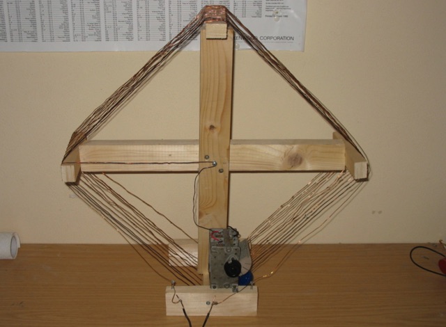 This loop antenna is intended to be connected as an antenna for receivers that do not have a built-in antenna such as an HF set or an old tube radio. This square barrel is wound on a wooden frame. It consists of two windings that are galvanically isolated from each other, a main and a coupling winding. The diameter is about 40 cm.
 -
 The F6AOJ RX splitter project was created to split the antenna signal from an LZ1AQ receive loop to multiple receivers, such as radios or SDRs. The design is simple to build and effective. The splitter, mounted on the back of the LZ1AQ control board, provides two outputs—one for an Afedri SDR and another for a K3 transceiver. Measurements show a damping of -3.01 dB at 1 MHz and -3.10 dB at 30 MHz, with a low SWR (max 1.07 at 30 MHz and 1.4 at 60 MHz).
 -
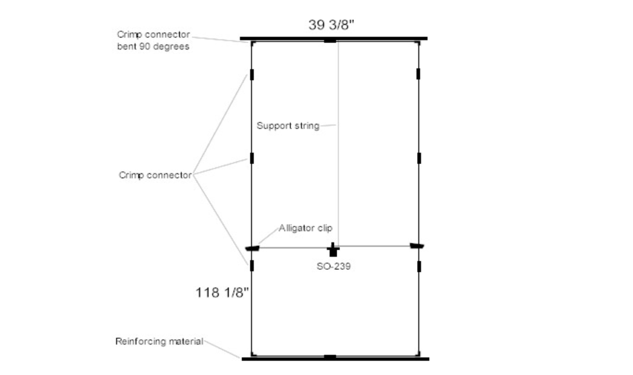 The K5USS 6 Meter Hentenna Project page on Hamuniverse provides detailed instructions on how to build a 6 meter directional antenna with 3.5 dBd gain. The project is presented with permission from K5USS, Charlie of Richardson, Texas. This directional antenna is a full wave loop on 6 meters, horizontally polarized but mounted vertically, with a 50 ohm impedance, ideal for 6 meter SSB operations. The page is useful for hams looking to construct their own directional antenna for improved performance on the 6 meter band.
 -
 145 MHz is the target frequency for this 2-meter Skeleton Slot Yagi Stack antenna project. The design focuses on feeding two stacked Yagi antennas using a skeleton slot radiator, which is a unique approach for VHF enthusiasts. The project details the construction process, including the loop tapered matching section for impedance matching, ensuring optimal performance. The use of specific components like the EH789 element holder and MB456 main mast bracket is highlighted, providing clarity on the assembly process. The construction utilizes 20x20 box aluminum bar for durability and precision. Key dimensions, such as the element length (ER-ED4) and main boom spacing (MM123), are meticulously outlined. This attention to detail aids in replicating the antenna design accurately. The downloadable PDF offers comprehensive instructions, making it accessible for amateur radio operators interested in VHF antenna construction. This project is particularly beneficial for those looking to optimize their 2-meter band operations. The inclusion of a skeleton slot radiator and loop tapered matching section demonstrates advanced techniques in antenna design, catering to both intermediate and advanced builders.
 -
 Demonstrates the construction of an active loop converter specifically designed for the Low Frequency (LF) bands, addressing common localized noise interference in LF reception. The design integrates a sharply tuned circuit and a tuned loop antenna, utilizing the loop as the sole tuned inductive element. By applying positive feedback, the converter significantly increases the loop's effective Q, achieving factors between 1000 and 2000, which sharpens tuning and reduces noise. The circuit employs an _NE602_ mixer stage, feeding its output to an HF receiver, with a crystal-locked local oscillator at 4 MHz. A 20-turn, 0.8-meter square loop antenna with 500 uH inductance is detailed, connected via 2 meters of figure 8 flex cable. The converter offers three selectable frequency bands: 195-490 kHz, 150-220 kHz (including the New Zealand amateur band), and 128-160 kHz (covering the European amateur band). Performance measurements indicate an effective 3dB bandwidth of approximately 100 to 200 hertz at 200 kHz. The article provides insights into component selection, including an _LF353_ op-amp and a trifilar wound transformer on a ferrite core. Sensitivity figures are presented, showing 7.5 uV of converted output per 1 uV/meter signal strength into a 50-ohm load, or 37.5 uV into an _FRG7_ receiver, highlighting its capability to extract weak signals from noise.
 -
 A full-wave delta loop antenna, approximately 141 feet in total wire length for the 40-meter band, offers a low angle of radiation, which is highly advantageous for DX operations. This design, optimized for both 30m and 40m, leverages a specific circumference calculation of 1005/F, ensuring resonance on both bands through a simple switching mechanism. The antenna's configuration enhances long-distance communication, making it a practical choice for hams with limited space. The resource details the construction process, including the use of a _Ceramic Knife Switch_ for band selection and an _RG-11_ matching section to achieve optimal impedance. It outlines the precise loop lengths required for each band, along with tuning secrets to ensure efficient operation. Requiring a minimum height of 12 feet, this antenna can be supported by a single mast or tree limb, making it suitable for suburban installations where stealth or space constraints are a factor.
 -
 Designing a collapsible 6-meter beam antenna involves careful consideration of element geometry and feedline matching, as demonstrated by VE3SMA's project. The construction draws inspiration from foldable dipole concepts and established wire beam designs like the Penn. State 40m beam and the DJ4SA Spiderbeam. Utilizing **4NEC2 modeling**, the author optimized element lengths for gain and bandwidth, observing the impact of end loops on resonant frequency and the need for compensation. Feeding the approximately 25-ohm balanced antenna with 50-ohm unbalanced cable required a specialized network. This setup incorporates a choke **balun** and a matching section built from two series quarter-wave transformers using readily available 75-ohm cable. On-the-air results validate the design, including a successful 1st double hop Es QSO with 10 Watts and satisfactory performance in the CW WW VHF Contest from FN05, where 41 grids were worked with 100 Watts, showing improved performance over a simple dipole.
 -
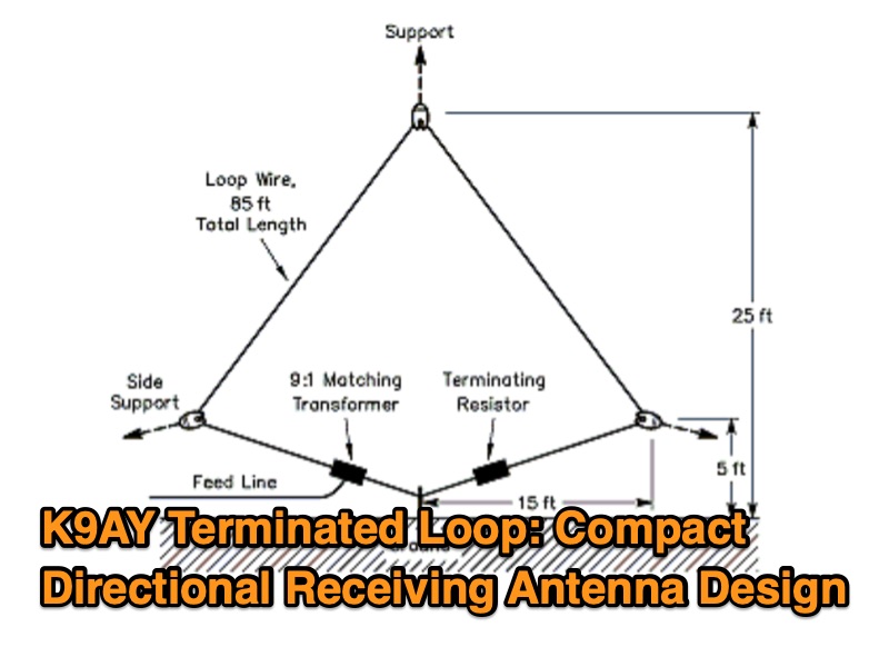 This resource presents the design and characteristics of the K9AY Terminated Loop, a compact directional receiving antenna system. The document details the antenna's physical and electrical configuration, consisting of a wire loop, a 9:1 impedance-matching transformer, and a terminating resistor. It describes how the antenna achieves directionality, favoring signals from the feed point end and rejecting signals from the terminating resistor end by several S units. The system is designed for low-band operation, specifically mentioning its application for improving reception on bands where space is a constraint. A four-direction system, utilizing two loops oriented at right angles with a relay-controlled switching system, is discussed. The resource includes a comparison of the K9AY loop's footprint to that of an equivalent EWE array, indicating the K9AY system requires approximately 1/7 the area while maintaining similar directional patterns. The design prioritizes signal collection sufficient for use with modest preamps, such as those integrated into HF transceivers. The article was originally published in QST in 1997.
 -
 This article explores the powerful features of AutoEZ as an Excel application working with EZNEC antenna modeling software. The article demonstrates how variables, equations, and formulas enable versatile antenna design and automatic optimization. Through practical examples including dipoles, inverted vees, delta loops, and monopoles, the author shows techniques for achieving resonance, implementing transmission line resonators for broadbanding, and optimizing antennas across frequency ranges. The step-by-step demonstrations cover unit conversion, coordinate calculations, segmentation considerations, and SWR optimization. This practical guide illustrates how AutoEZ extends EZNEC's capabilities, making complex antenna modeling more efficient and accessible.
 -
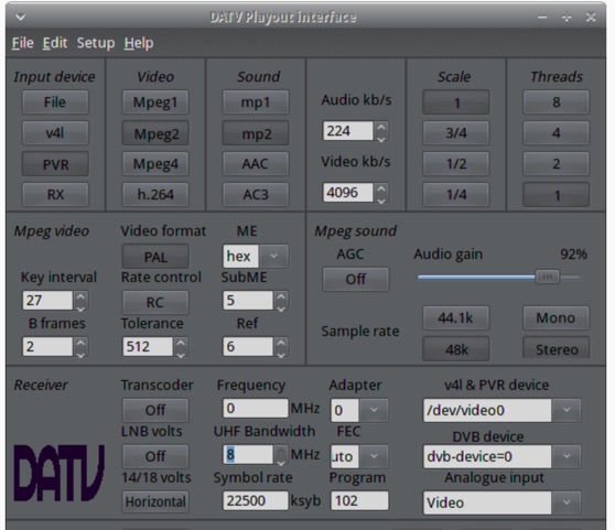 The ZL1WTT resource details an experimental software-based Digital Amateur Television (DATV) system, demonstrating the multiplexing of up to six standard-definition (SD) and one high-definition (HD) channel utilizing _h264 compression_. The author encountered peak data rates reaching 32 Mbit/s, necessitating a shift to Freeview and Sky settings (22.5M Sym/s 3/4FEC) to manage bandwidth. The setup employs four networked computers, with a laptop functioning as the multiplexer to re-code PIDs for various inputs, including looped MPEG2 playlists, MPEG2 encoder card input from a VCR, satellite feeds, and an off-air UHF receiver. The system highlights the inherent flexibility of the DVB transport stream, supporting diverse formats such as MPG2, h264, AC3, and AAC. A significant advantage of this software-defined approach is the absence of video quality degradation from stored MPEG2 files to the displayed output, coupled with the ease of reconfiguring settings for MPEG2 encoder cards (e.g., size, bit-rate, frame rate, video input, coding format) and satellite receiver cards (e.g., frequency, LNB volts, symbol rate, FEC). The author also discusses the development of a new graphical user interface (GUI) using _Gambas_ for Linux, aiming to simplify configuration for this DATV project. Specific hardware components mentioned include Hauppauge WinTV PVR-150 and Nova-S plus cards, with a focus on optimizing analog video input via Y/C (S-video) to minimize frequency roll-off. The resource also provides insights into data rates for HD (1080i) content, recommending 8 to 12 Mb/s for optimal performance. Software utilized includes _Ubuntu Studio 10.04_, WinFF, VLC, and TMPGEnc Editor, underscoring the project's reliance on open-source tools and a foundational understanding of LAN networks and DVB transport streams.
 -
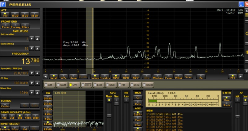 Investigates the performance characteristics of the _AAA-1_ active loop antenna across Very Low Frequency (VLF) and Low Frequency (LF) bands. It details the antenna's frequency response, explaining how a small loop with a low input resistance trans-impedance amplifier maintains a flat frequency response to electromagnetic field intensity E. The document illustrates current source and Thevenen equivalent circuit models for small loops, emphasizing the transition between these models based on frequency and load impedance. Measurement setups for both high frequency and VLF/LF responses are presented with diagrams, including methods for simulating current and voltage sources. The analysis includes normalized plots of the _AAA-1_'s frequency response for three distinct loop inductances, derived from measurements using a _Perseus SDR_ at 1 kHz bandwidth. It provides calculations for the noise floor at VLF/LF frequencies, comparing ambient noise levels with the antenna's internal noise floor. The resource also documents practical reception experiments in a semi-urban environment, showcasing successful reception of time transmitters like _MSF_ at 60 KHz and _SAQ_ at 17.2 KHz, along with various navy digital transmissions and Russian Alfa beacons.
 -
 Constructing a 4:1 Guanella current balun involves cross-connecting two 1:1 current baluns. At the low-impedance end, transmission lines from each balun are connected in parallel, while at the high-impedance end, they are connected in series. This configuration allows the device to achieve a 1:4 impedance ratio, effectively transforming a 200-ohm load to 50 ohms. The balun described utilizes **FT240-43 toroids** wound with 2.5mm2 twisted pair cable for 8 turns, intended for use with a 20m **Deltaloop antenna**. Measurements performed with a 200-ohm resistor demonstrate satisfactory VSWR and impedance characteristics across the HF bands. The article compares the performance of 2.5mm2 cable versus 1mm enameled wire, recommending the former for superior efficiency. Emphasis is placed on maintaining short core-terminal connections to optimize performance. Additional considerations include the option of integrating a separate Common Mode Choke (CMC) for enhanced common mode current suppression, especially if the balun's inherent suppression is not prioritized.
 -
 Understanding how radio frequency interference (RFI) is coupled into equipment and subsequently detected is crucial for amateur radio operators. This guide delves into the fundamental mechanisms of RFI, particularly focusing on detection at semiconductor junctions and the unintended antenna action of system wiring. It explains that most RFI detection follows a square law, meaning a 6 dB reduction in RF signal can result in a 12 dB drop in detected audio, offering a practical approach to mitigation. The resource also clarifies the concept of common mode versus differential mode signals, detailing how cable imperfections can convert common mode antenna current into differential signals. It addresses the critical "Pin 1 Problem" in audio interfacing, a common design flaw where cable shields connect to the circuit board instead of the shielding enclosure, leading to significant RFI issues. Practical solutions, such as proper shielding, using twisted-pair cables, and strategic bonding of equipment, are discussed to effectively reduce or eliminate RFI. The guide emphasizes the importance of proper filtering and the often-misunderstood concept of "ground" in electrical systems, distinguishing between earth ground, equipment ground, and circuit common. It provides insights into minimizing loop area in wiring to reduce inductively coupled noise and antenna action, drawing on the author's extensive engineering background and ham radio experience.
 -
 HAMgpt offers a personalized amateur radio experience, leveraging AI to provide real-time operational guidance. It integrates live propagation data, current band conditions, and operator-specific context, including callsign, QTH, license class, and station equipment, to deliver relevant answers. The system can identify open HF, VHF, and UHF bands, suggest workable DXpeditions and POTA/SOTA activations, and provide accurate repeater offsets and CTCSS/DCS tones for local repeaters. Unlike general-purpose chatbots, HAMgpt avoids fabricating frequencies or license privileges, instead relying on actual data for its responses. It supports antenna design calculations for various types like Yagi, dipole, vertical, and magnetic loop antennas, offering to-scale dimensions. The platform also assists with license exam preparation and provides satellite pass predictions tailored to the user's location. It supports multiple countries, including the United States (FCC Technician, General, Extra), Canada, the United Kingdom, Australia, Japan, and Argentina, incorporating their specific band plans and power limits.