Search results
Query: pdf
Links: 519 | Categories: 0
-
 ARRL review ICOM IC-756 pro III HF/6 meter transceiver at central michigan ARC PDF File
 -
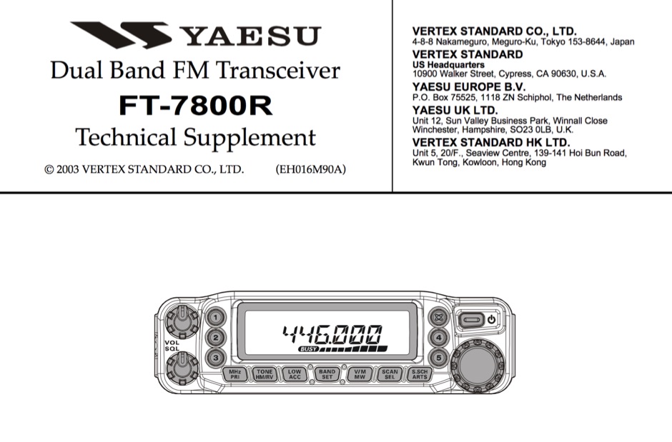 Service manual in PDF Format for the Yaesu FT-7800 transceiver
 -
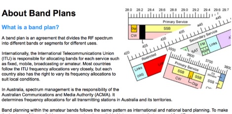 Australian amateur radio band plans in pdf format
 -

-
 A PDF presentation about Amateur Radio and Linux by By: Dave Mamanakis. A beginners guide to Linux for radio amateurs, this presentation cover basic concepts of the open source operative system, from the basic installation to the setup of ham radio programs.
 -
 Understanding and solving RF interference problems using ferrite
 -
 The Kenwood TS-2000 All-Mode Multiband Transceiver review
 -
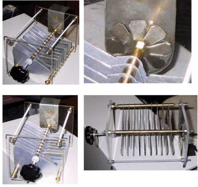 Building a high voltage (5KV), variable plate capacitor (17 to 220pF)
 -
 Balun case construction, tipically to host toroid cores. Size of case depends on power to handle. By DL5DBM
 -
 A 5 band two element quad antenna working from 20 to 10 meters using hardware-store parts or modifying an existing commercial triband quad by KC6T
 -
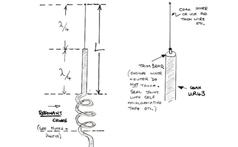
 The Resonant Feedline Dipole (RFD) HF antenna design utilizes a single piece of coaxial cable and a stranded wire section, forming a 1/4-wavelength radiator. This configuration, based on a 1997 ARRL Handbook design (page 20.17), functions by RF traveling on the inside of the coax shield and returning on the outside, creating the second half of the dipole. A choke wound into the feedline prevents RF current from flowing back down the feedline. Construction details include using RG-58a/u coax for a 75m version, with a 1/4-wavelength section of stranded wire soldered to the center conductor. The document provides choke dimensions for RG-213, RG-8, and RG-58 coax across 3.5 MHz to 28 MHz, specifying cable length and number of turns. Dipole dimensions are also tabulated for frequencies from 3.6 MHz to 28.4 MHz, listing overall length and individual leg lengths. Field tests included deployment near Bryson City at 5 feet off the ground and as a sloper during WCARS Field Day in Asheville, yielding successful local and regional contacts.
 -
 W3EDP antenna assembly instructions and dimensions with pictures in this PDF File
 -
 An home made vertical dipole antenna made with simple material. The antenna has a total length of aproximately 16 feet. In this article appeared on June QST 2019, the author explain how he reached the optimal confirugation changing and adjusting the lower part of the antenna, trimming and spacing correctly the copper wire. PDF File to downloas
 -
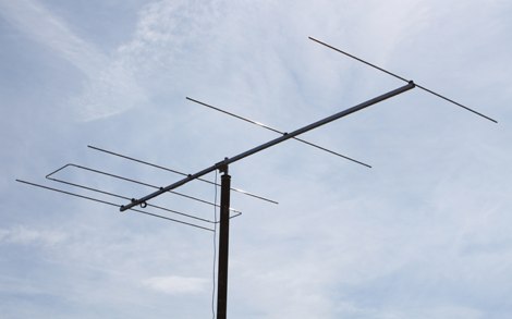 A Loop Fed Array Yagi antenna for 50 MHz featuring 11 dBi gain and 23 f/b ratio. In this excellent page the author even includes a detailed drawing in DWG format, with element lenght and spacing measures, in a separa file a full list of material list needed to build this yagi antenna including source and price, the EZnec file for this antenna plan, and a lot of pictures of this LFA Yagi for 50 Mhz. A ten page PDF file containing all infos, is also available to download.
 -
 A scanned PDF of this interesting book on HF Dipole antennas published by Stanford Research Institute
 -
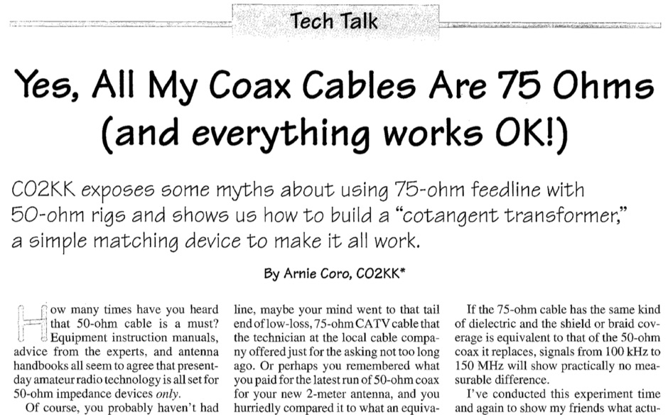 CO2KK exposes some myths about using 75-ohm feedline with 50-ohm rigs and show how to build a cotanget transformer
 -
 ARRL Laboratory Expanded Test-Result Report Kenwood TS-570D
 -
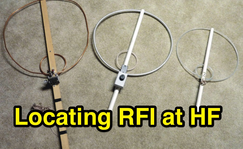 A proven and practical approach to dealing with RFI from grow lights and more.
 -
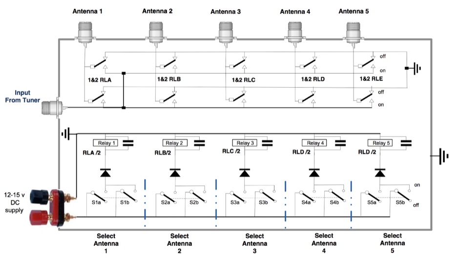 A project of a 5 Antennas Relay Switch Box, all Switches & Relays have both contacts wired in parallel to improve reliability of operation, to prevent static build up, when an antenna is not in use the feeder coax is grounded.
 -
 Ebook by Akira Matsuzawa Tokyo Institute of Technology, Building blocks in RF system and basic performances, Device characteristics in RF application , Low noise amplifier design, Mixer design and Oscillator design
 -
 For those who are interested in telegraphy, for those who would like to learn it, for those who love it, and for those who want to improve their skills in it
 -
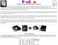 Hidden transmitter hunting, often called fox hunting or Amateur Radio Direction Finding (_ARDF_), presents a unique challenge for radio amateurs. This resource details the _PicCon_ controller, a specialized device designed to automate the transmission of signals for such events. It integrates with a standard radio transceiver, functioning similarly to a packet radio TNC, by controlling the Push-To-Talk (PTT) line and injecting audio tones or modulated CW Morse code into the microphone input. The _PicCon_ unit is field-programmable using DTMF tones received via the radio, storing all settings in EEPROM for power-off retention. Its compact design and low power consumption (a few milliamps from a 7-35VDC source) make it suitable for remote deployment. An onboard LED indicates operational status, and a push-button allows manual start/stop of transmissions without DTMF. Typically supplied as a kit, _PicCon_ includes a PCB, components, and a comprehensive manual (available in HTML, RTF, and PDF formats). The kit provides a six-conductor interface cable, but users must supply radio and power plugs due to varied configurations. Byon, _N6BG_, developed this controller, which is available from the Byonics website.
 -
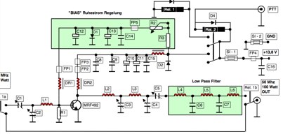 6-Meter Solid-State 100W Linear Amplifier complete documentation German and English
 -
-
 An optimized QRP transceiver for 40 meters band
 -
 A practical approach to microwave signal analysis for the home experimenter
 -
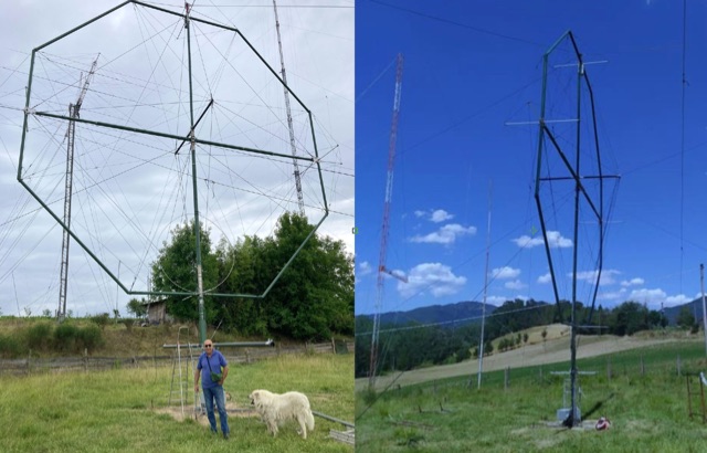 A monster magnetic loop antenna for 160 meters band. This Magnetic loop is optimized for 1840 Khz + 50 Khz. PDF Article published on La Radiospecola 10.22
 -

-
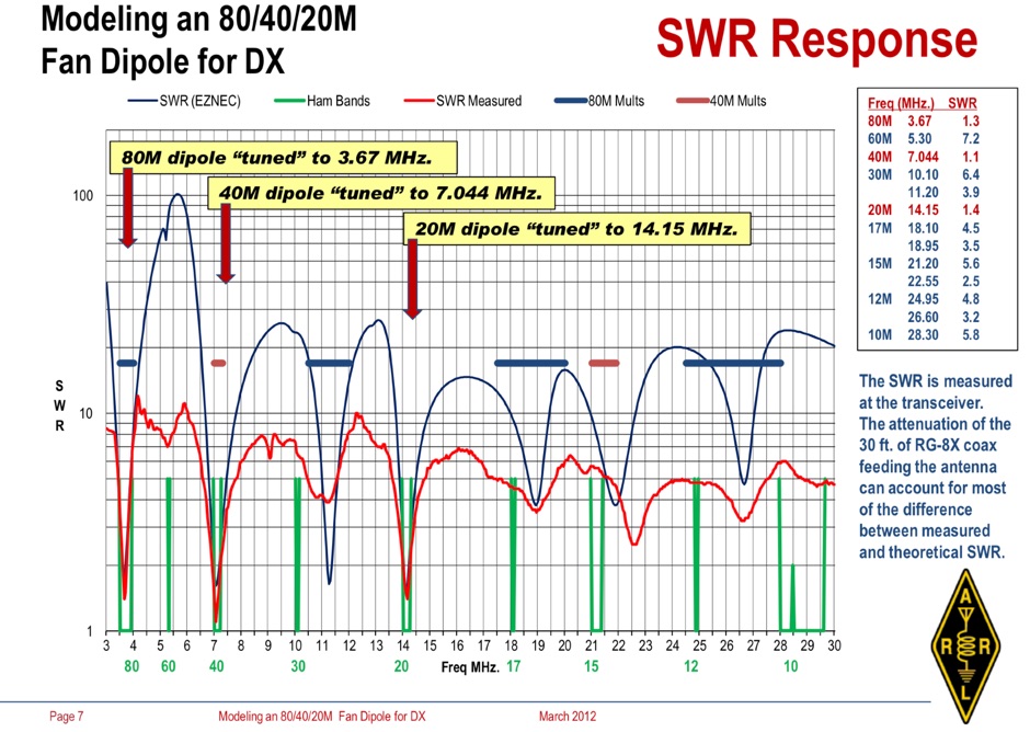 Operating an 80/40/20M fan dipole for DX is analyzed through EZNEC modeling, focusing on the antenna's performance in a real-world, low-height installation. The resource details the physical construction and SWR measurements of the fan dipole, comparing them against EZNEC simulations. It also incorporates High Frequency Terrain Analysis (HFTA) data to illustrate typical DX elevation angles for various regions from New England, providing a crucial context for evaluating antenna patterns. The analysis presents EZNEC-generated azimuth and elevation patterns for each band (80M, 40M, 20M) at specific frequencies, showing gain figures at different elevation angles relevant to DX propagation. It compares the modeled SWR with measured SWR, attributing discrepancies to coax attenuation. The study concludes with observations on the antenna's azimuth performance (omnidirectional within ±1.5 dB) and its less optimal elevation gain at desired DX angles, highlighting the impact of low antenna height on DX capabilities.
 -

-
 An Experimental, High-efficiency, Graphic-Tunable Magnetic Loop antenna and loop controller in a 52 pages PDF presentation with drawings and pictures
 -
 A large printable PDF file representing the world time zones. This map gives an overview of current local times around the world. If you ever asked yourself what time zone am i in, find your answer here.
 -
 A 5/8 wave antenna, can be fed with ladder line from the center insulator to tuner.
 -
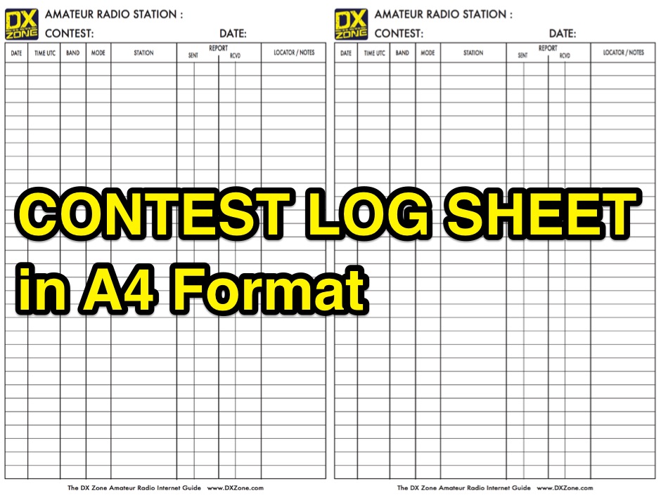 An amateur radio contest log sheet printable in A4 format, useful for portable operations, free to download PDF File.
 -
 Istructions to use the IFD demodulator
 -

-
 Green that aluminum into something useful right in your own backyard by WB2CQM
 -
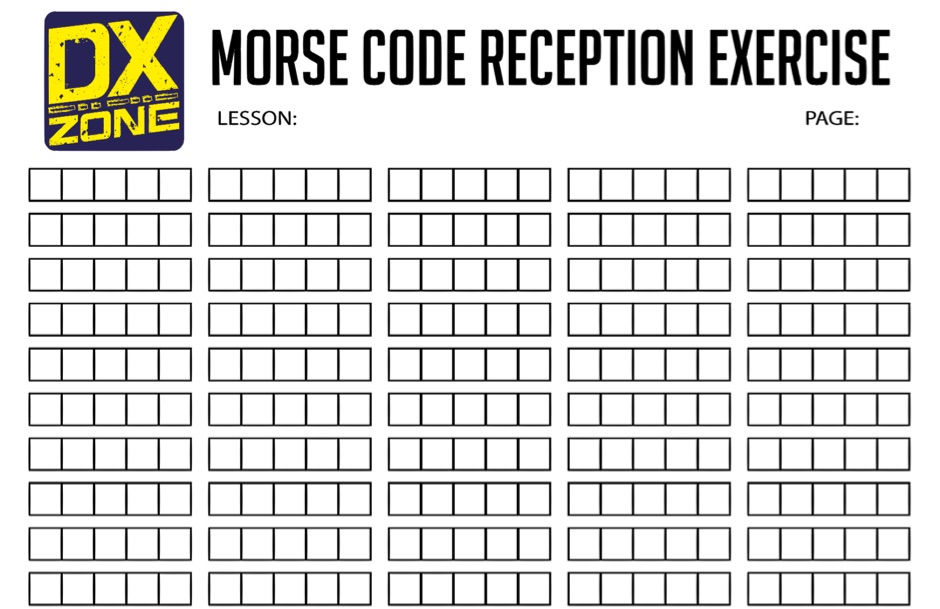 Useful exercise sheet to learn morse code reception. In A4 format PDF File, it contains groups of 5 characters commonly used while learning morse code reception.
 -
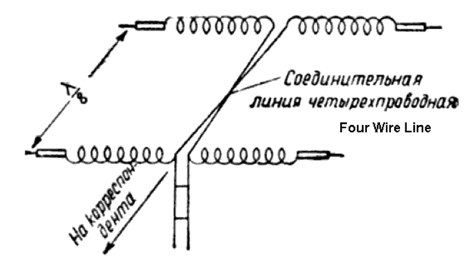 This antenna is intended for the 20-meter Band. There are two Voltage Fed Helical Dipoles, made with 2 slinky that fed with phase shift in 90 degree
 -
 Understanding Common Mode and Differential Mode Currents on Transmission Lines by K9YC
 -
 Amateur radio good operating practices by KG9OM
 -
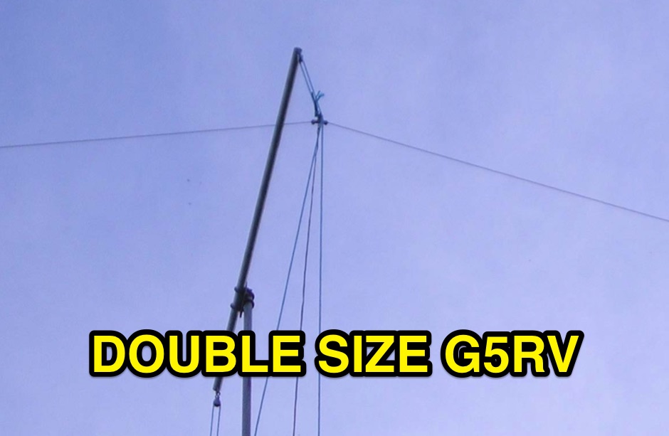 Building the double size G5RV antenna, part list, assembly part, dimensions and assembly instruction in a pdf document
 -
 A PDF File of a Maria Maluca multiband HF antenna with schematic diagram, dimension and plan
 -
 This PDF document details the construction of a **70 MHz** Big Wheel antenna, a horizontally polarized omnidirectional array. The design utilizes three full-wave loops, each approximately **2160 mm** in diameter, arranged in a triangular configuration. The resource provides mechanical dimensions for the antenna elements and a comprehensive bill of materials, specifying component quantities and types, such as M8 stainless steel bolts, 15x15x1.5 mm square aluminum tubing for spacers, and 8 mm aluminum rod for the arcs. The central hub is constructed from two 160x160x8 mm aluminum plates, with four 40 mm long polyamide insulators supporting the radiating elements. The feed system incorporates a 50 mm diameter aluminum pipe for mounting and a matching stub constructed from a 120x20x2 mm aluminum sheet, connected via M8x10 mm bolts. The resource includes a diagram illustrating the mechanical dimensions and assembly points, including the N-connector fixing point and the center conductor attachment. The project was published on May 25, 2011, by Peter OE5MPL and Rudi OE5VRL. DXZone Focus: PDF | 70 MHz Big Wheel | Mechanical Dimensions | **2160 mm** loop diameter
 -
 Demonstrates the construction of a custom programming cable for Yaesu VX-7R and VX-5R handheld transceivers, enabling computer interfacing for memory management and frequency coverage adjustments. The resource details a six-transistor circuit design, powered by the computer's RS232 interface, utilizing readily available and inexpensive discrete components. It includes a complete bill of materials, specifying transistors like the _2N2222_ and _2N3906_, diodes, and resistors, along with a matrix board layout for compact assembly within a 75x50x25mm enclosure. The guide provides practical tips for working with matrix board, such as scoring and snapping, track cleaning, and component soldering order. It outlines the specific connection requirements for both the VX-7R (via Yaesu's CT-91 breakout lead with a 2.5mm stereo jack) and the VX-5R (via CT-44 or a four-section jack), detailing signal and ground pinouts. The author successfully tested three circuits, documenting the one with complete two-way communication, allowing users to program their rigs with software like _VX-7 Commander_ and achieve capabilities beyond commercial cables, including band adjustments.
 -
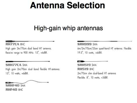 The document titled 'Extending the Range of Your Handheld' by WG7S is a guide on how to extend the range of your handheld VHF UHF transceiver by using an external antenna. It provides information on comparing popular models, selecting the right antenna, and resources for amateur radio antennas.
 -
 Don't neglect one of the most important parts of your station!
 -
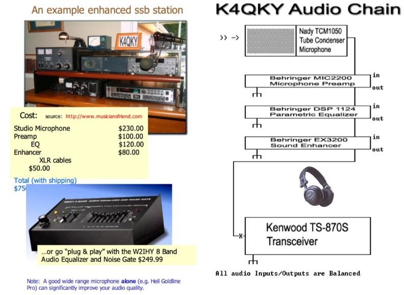 Enhanced SSB Audio (ESSB) is a specialized operating mode that extends the capabilities of traditional Single Sideband (SSB) voice transmissions. This presentation by K4QKY delves into the technical aspects of ESSB, discussing its advantages and the ongoing debates within the ham radio community regarding audio quality and bandwidth usage. ESSB aims to provide clearer and more natural-sounding audio, which can enhance the overall communication experience for operators. The presentation covers various topics, including microphone selection, audio processing techniques, and the importance of proper equalization. It also addresses the controversies surrounding ESSB, such as the potential for interference and the debate over whether it strays too far from traditional SSB practices. By understanding these elements, amateur radio operators can make informed decisions about their audio setups and contribute to discussions about the future of SSB operations.
 -

-
 Ground Plane - 1/4 wave vertical, J-Pole, 3 Element Yagi Beam and simple antenna supports