Search results
Query: feed
Links: 563 | Categories: 11
Categories
- Antennas > Feed Lines
- Antennas > Resonant Feedline Dipole
- Antennas > Baluns
- Shortwave Radio > Broadcasters
- Antennas > Microwave
- Antennas > Feed Lines > Open Wire
- Internet and Radio > Police Scanners
- Radio Scanning > Police Scanning
- Radio Scanning > RailRoad
- Internet and Radio > Tutorials
- Internet and Radio > Web Cams
-
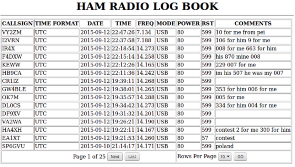 Call Book Log 3.0 is a web-based logging solution for amateur radio operators, designed for self-hosting on a web server with MySQL/MariaDB and PHP 7+ support. It provides a mobile-friendly interface for viewing, adding, editing, deleting, backing up, and restoring QSO logs. The software features a streamlined setup process, allowing users to quickly deploy a personal logging system accessible via any web browser. Key functionalities include displaying the last **5** contact dates for previously worked stations, enhancing log management by providing immediate historical context during QSO entry. The system also includes a central administrative section for authenticated users to manage log entries. The 3.0 version represents a significant code overhaul, focusing on improved performance and a more *visually appealing* user experience compared to earlier iterations. Enhancements include better pagination, a redesigned menu with icons, and color-changing rows for improved readability. The add log page now incorporates a one-click time update feature, addressing user feedback regarding time synchronization during rapid QSO entry. This iteration builds upon previous versions like 2.1, which corrected an automatic _UTC date_ bug, and 2.0, which featured a full rewrite to resolve browser quirks and optimize search functions. The software's evolution demonstrates a commitment to functional stability and user interface refinement.
 -
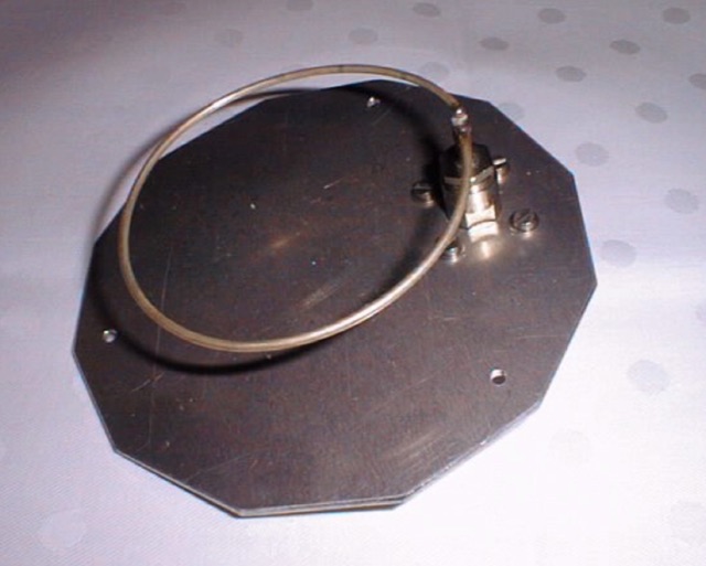 A parabolic dish ring feed optimum resonance frequency of 1325MHz
 -
 Presents construction details for Moxon antennas, specifically focusing on 10-meter and 17-meter band configurations. It covers practical aspects of building these directional wire arrays, including element spacing, feedpoint considerations, and material choices for optimal performance. The resource emphasizes homebrewing techniques suitable for amateur radio operators. Discusses the advantages of the Moxon rectangle design, such as its compact footprint compared to a full-size Yagi and its favorable front-to-back ratio. It provides insights into achieving proper impedance matching and structural integrity for portable or fixed installations. The content includes photographic examples of constructed antennas. Explains the iterative process of tuning and optimizing Moxon antennas for specific frequency segments within the 10m and 17m bands. It offers guidance on minimizing SWR and maximizing gain, drawing from real-world building experiences to assist constructors in replicating successful designs.
 -
 DK7ZB's fan dipole designs address the challenge of operating multiple HF bands with a single feedline, providing practical construction details for **multiband wire antennas**. The resource outlines specific lengths for half-dipoles across various band combinations, including 10-15-20m for classic bands and 12-17-30m for WARC bands. It emphasizes the importance of proper spacing between resonant elements to avoid impedance interaction and high SWR, a common issue when frequencies are too close. The article details the use of **current baluns** built with FT240-43 or FT140-43 cores, specifying turns and cable types for 1KW and 400-Watt power levels. It includes a correction table for adjusting dipole lengths based on frequency shifts, aiding in fine-tuning resonance. The 20+40m dipole is noted for its ability to operate on 15m with an ATU, demonstrating versatility.
 -
 Accurate frequency measurement is crucial for amateur radio operators, particularly when building or troubleshooting transceivers and test equipment. This resource details the construction of a _PIC microcontroller_-based frequency counter, providing a practical solution for precise frequency display. The design incorporates an LCD readout, offering clear visual feedback of measured frequencies. The counter can operate as a standalone unit, useful for general bench testing, or be integrated directly into a receiver. Its built-in offset functionality allows for seamless integration, enabling the display of the received signal frequency rather than the intermediate frequency. The project focuses on accessible components and construction techniques, making it suitable for homebrew enthusiasts. Key features include a measurement range up to **50 MHz** and a compact form factor.
 -
 Listen to Missouri State Highway Patrol live scanner
 -
 Hose Company 1 East Rockaway Fire Department Official Page. Scanning FDNY & East Rockaway Fire
 -
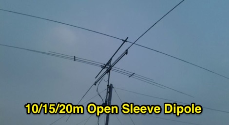 Based on a simple project based on a 2 elements Yagi for 20m band, and then becomed a triband yagi with a open-sleeve feed system
 -
 The resource details the construction of a multiband trap-style Inverted-V antenna designed for operation on 3.5 MHz, 7 MHz, 14 MHz, 21 MHz, and 28 MHz. It presents specific winding data for the traps, including the number of turns, wire gauge, and coil former dimensions, crucial for achieving resonance on the target bands. The document provides a parts list and a diagram illustrating the antenna's physical layout and trap placement. It outlines the process for building the traps using PVC pipe formers and specifies the required capacitor values for each trap. The design emphasizes a practical approach to achieving multiband operation with a single feedline, a common goal for HF operators with limited space. The document includes a table with antenna segment lengths for each band, allowing for precise replication of the design. It also offers insights into tuning and adjustment, ensuring the antenna performs optimally across the designated amateur radio bands.
 -
 Rail Radio Communication Feeds broadcasted from all over the United States and beyond.
 -
 Long Beach Los Angeles county live scanner feed
 -
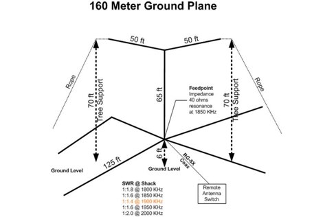 The 160 meter ground plane is constructed from #10 stranded insulated wire available in most hardware stores. The feedpoints / tiepoints use PVC pipe T-sections Article by W1TR
 -
 Ten essential tips and truisms for understanding HF antenna: Non-resonant wire dipole antennas fed with open-wire line and an antenna tuner can function effectively as multiband antennas, as detailed in "The Classic Multiband Dipole Antenna" by WB8IMY in March 2004 QST. Coaxial cable, unlike balanced parallel-wire feed lines, can cause RF to travel on the outer shield braid, leading to RF feedback to the station; a 1:1 balun at the dipole center can mitigate this by isolating the unbalanced coaxial feed line. Antenna gain is achieved by shaping and directing RF energy, with beam antennas concentrating power in a specific direction, and wire antennas also exhibiting shaped radiation patterns. An antenna tuner's primary role is to match the transceiver's 50-ohm output to the antenna system's impedance, allowing modern transceivers to deliver full power. Wire antennas do not always require center feeding; end-fed long wires or off-center-fed dipoles (like the Windom) can be used, though they often necessitate an antenna tuner and a counterpoise or radial network. Dipole antennas do not need to be perfectly horizontal; their legs can be bent or inclined, which affects feed point impedance and may require SWR experimentation with coaxial feed. Vertical antennas shorter than a half wavelength require an efficient ground system, typically comprising elevated or buried radial wires, with more radials generally leading to better efficiency. A 1:1 SWR indicates an impedance match but does not guarantee antenna efficiency; an inefficient vertical antenna with a poor ground system can show a low SWR while wasting most RF as heat. Investing in high-quality, low-loss feed line, especially coaxial cable, is crucial for maximizing RF signal transfer and overall antenna system performance.
 -
 A 17 3/4-inch radiating element and 18 3/4-inch ground plane radials form the basis of this quarter-wave ground plane antenna for 2 meters FM. The design, attributed to AA1PG, utilizes a panel-mount SO-239 UHF connector and three lengths of #12 copper wire, with a total material cost estimated at $3.00. Construction involves soldering the elements directly to the SO-239, emphasizing thorough solder flow for robust connections. Recommended feedline includes _RG-8X_ for longer runs, with _RG-58_ acceptable for shorter lengths, cautioning against _RG-174_ for VHF applications due to high loss. The antenna is designed for elevated deployment, such as in trees or on roof gables, to maximize line-of-sight propagation. It aims to improve repeater access compared to typical rubber duck antennas, even with low power output.
 -
 The official web-site of the firm IK-Telecom, Finland, manufacturer of base station antenna-feeder systems
 -
 Live feed for NHP rural areas of Moapa Laughlin Primm Alamo Indian Springs
 -
 Presents the construction of a 2-meter **Skeleton Slot Yagi** stack, detailing the design process and practical considerations for VHF operation. The author shares insights from building and testing this antenna, emphasizing its performance characteristics for local and extended range contacts. The project outlines the specific dimensions and materials used, providing a clear path for other radio amateurs to replicate or adapt the design for their own stations. The resource covers the unique aspects of the Skeleton Slot radiator, explaining how its geometry contributes to gain and pattern control. It includes discussions on impedance matching and feedline considerations crucial for optimizing power transfer and minimizing SWR. The article draws on real-world testing, offering practical results that validate the theoretical design. This project serves as a valuable reference for those interested in custom VHF antenna solutions.
 -
 The NB6Zep Antenna, an electrically shortened 80-meter end-fed wire, addresses space constraints for low-band operation by integrating two loading coils into a 37-foot wire. This design, modeled with _EZNEC_, explores configurations like the quarter-wave sloper and inverted-L, with the latter providing a more vertical radiation pattern and practical backyard deployment. The resource details specific coil construction, recommending 21 uH coils made from _BW coil stock #3026_ or similar, and outlines wire segment lengths for optimal tuning. Performance analysis indicates a radiating efficiency of approximately 27% with good ground conductivity, resulting in a signal typically 3-4 dB down compared to a full-size quarter-wave vertical. The antenna exhibits a narrow bandwidth, around 50 kHz, due to its high Q, necessitating a tuner for broader band operation. Feedpoint impedance is low, with ground resistance playing a critical role in achieving a usable SWR. The article emphasizes the importance of an effective ground rod at the feedpoint for proper operation and tuning, suggesting an antenna analyzer for precise adjustments. It confirms the antenna's suitability for DX, citing successful contacts from Oregon to the East Coast and Hawaii on a 160-meter variant, making it a viable option for urban operators seeking low-angle radiation on 80 meters.
 -
 St. Louis Repeater runs four repeaters in the St. Louis Metro Area, including two with autopatch capability.
 -
 City of Milwaukee Fire Department Live Audio Feed
 -
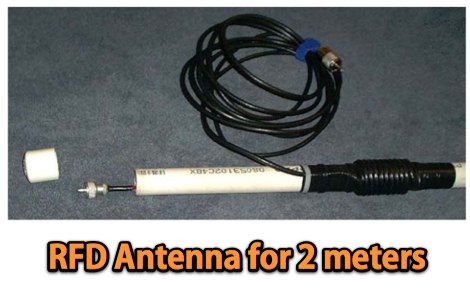 Building a Resonant Feed line Dipole for 2 Meters
 -
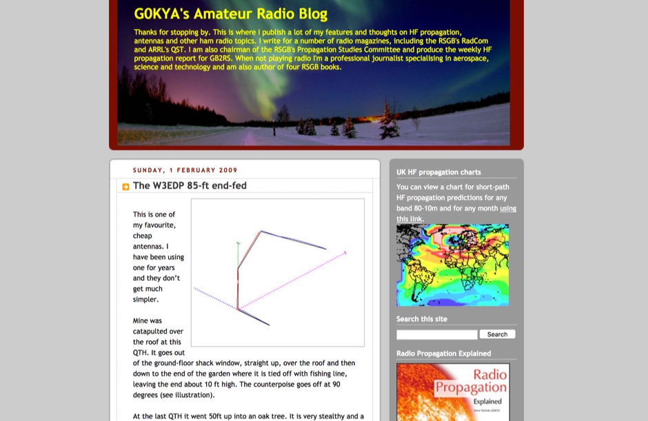 A wire antenna feeded with an unsymmetrical feed and a 1:4 balun can be tuned from 6 to 80 meters band but can be noisier than a dipole and cause RF in the shack
 -
 Live audio of the National Hurricane Center’s Skywarn Nets. This live feed covers several different states, and locations throughout the US including: TX, LA, MS, AL, FL, GA, SC, NC, VA, MD, DE, PA, NJ, NY, CT, RI, MA, VT, and ME
 -
 Constructing an effective directional antenna for the 40-meter band presents unique challenges due to its physical size requirements. This resource details the homebrew construction of a 2-element _Moxon_ Yagi antenna specifically designed for 7 MHz operation. The author, TA7OM, provides a visual guide to building this antenna, showcasing the boom, element mounting, and feedpoint connections through a series of high-resolution photographs. While textual descriptions are minimal, the imagery clearly illustrates the mechanical aspects of the antenna's assembly. The _Moxon_ rectangle design offers a compact footprint compared to a full-size Yagi, making it a practical choice for many hams with limited real estate. The visual documentation allows builders to replicate the antenna's structure, including the use of PVC pipe for element support and the method for spacing the driven and reflector elements. The project emphasizes practical construction techniques for achieving a directional pattern on a challenging HF band, suitable for DXing and contesting.
 -
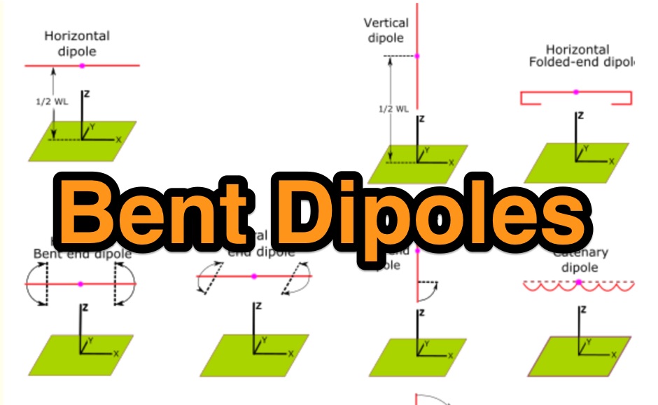 Antenna modeling discussions about What happens if... a dipole is bent horizontally, laterally, vertically. Zig-zag, meander, catenary curve. Effect of sag, elevation, radials. OCF off-center feed, harmonics. Includes 4NEC2 antenna models for each study.
 -
 Live Police and Fire scanner feeds from Albion PA, Erie County PA USA.
 -
 Several HD video overlay devices are offered, including the GeoStamp HD, which overlays GPS latitude, longitude, heading, speed, altitude, date, time, and depth onto AHD, HD-TVI, and HD-CVI (720p/1080p) video sources. The VideoStamp HD allows user-defined text overlays on similar HD video inputs, while the VideoStamp Keyboard HD enables text input via a PS/2 keyboard for video overlay. For commercial applications, the PostMark HD integrates with cash registers and POS terminals to overlay transaction data onto security camera feeds. Beyond HD video solutions, the DTMF-8 DTMF Decoder provides remote control capabilities for up to eight devices or relays using touch tones from a radio or other audio source. This decoder supports four operational modes and includes password protection, storing all settings in non-volatile EEPROM memory. The product line also includes standard definition OSD, RS-232, GPS, and POS text inserters, along with various DTMF encoders and DVR solutions.
 -
 Demonstrating the construction of a short dipole antenna tailored for the 60 meter band, this resource provides detailed instructions for radio enthusiasts with limited space. The design incorporates inductive loading using two inductors (L1/L2) made from PVC tubes, allowing for effective operation on 5 MHz. The antenna consists of 12 meters of wire, divided into four sections, with specific dimensions and materials outlined for optimal performance. Results from users indicate that this antenna can significantly enhance DXing capabilities on the 60 meter band. Feedback from operators suggests that while the design is effective, adjustments may be necessary based on individual setups, such as coil diameter and wire gauge. Many users report successful construction and operation, with some experimenting with variations to improve resonance. The practical application of this antenna design has led to successful contacts and improved signal quality, making it a popular choice among 60 meter band operators.
 -
 The 60-page PDF document, "Antenna Systems and Theory For The Non-Technical Ham" by Jim Abercrombie, N4JA, provides a foundational understanding of antenna systems. It explains basic antenna theory, including how antennas work, electromagnetic wave polarization, and the role of frequency. The resource details various antenna types such as flat top dipoles, inverted-V dipoles, shortened loaded dipoles, G5RV dipoles, Carolina Windoms, and end-fed configurations. Vertical antennas, including ground-mounted trapped verticals and inverted-L verticals, are also covered. Directional beam antennas like monoband Yagis, cubical quads, and log-periodic arrays are discussed. Propagation modes, including ground-wave, direct wave, and skywave propagation, are explained in detail, with specific attention to the D, E, and F layers of the ionosphere and their effects on HF communication. Technical concepts such as standing wave ratio, decibels, resistance, and reactance are defined, along with calculations for half-wave resonant dipole lengths. The document addresses feed-line radiation, balun applications, and critical antenna and tower safety considerations. It aims to dispel common antenna myths and educate hams on making informed antenna choices.
 -
 Illinois Cook County, police scanner includes Chicago Fire Dispatch channels (North, South, and HazMat)
 -
 Balanced feed with coaxial line by John F. Clemens W9ERN
 -
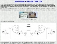
-
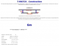 The T-Match with its balanced feed point is one method of feeding a Balanced Dipole.
 -
 Oakcallsigns.com specializes in custom-crafted oak call signs, presenting various designs for amateur radio shacks. The resource showcases different styles, including standard call sign plaques and options featuring iconic ham radio silhouettes like the _D-104_ microphone. Each item is described with pricing, ranging from $15.00 to **$25.00**, and includes details on shipping and seller reputation. The platform highlights the craftsmanship involved, emphasizing personalized scroll-saw work on each oak piece. It details the seller's positive feedback rating of **99.4%** from over 10,000 transactions, indicating a reliable source for these unique accessories. The site also provides information on the number of units sold for specific designs, such as 2,338 for the standard call sign gift and 554 for the smaller personalized version. This commercial offering focuses on decorative and personalized items for the ham radio enthusiast, distinct from operational equipment. It serves as a direct retail channel for custom shack adornments.
 -
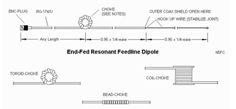 Experiences with the end-fed dipole based on the concepts presented by J. Taylor in an article titled RFD-1 and RFD-2: Resonant Feed-Line Dipoles in QST. August 1991.
 -
 Interactive home for radio contesters. Includes scores database, access to contester chat, forums, real-time posting and near-real-time news feed.
 -
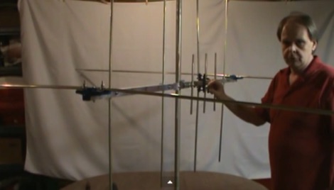 6m/2m/70cm Yagi Antenna Built from Old TV Antenna This turned out to be a great little antenna. It works the 6 meter, 2 meter and 70 centimeter bands. You can use one common feedpoint or two seperate feedpoints depending on how you would like to connect this antenna to your transceiver.
 -
 Demonstrates the principles of effective HF multi-band antenna systems, emphasizing the use of non-resonant antennas, understanding line attenuation, and the proper application of transmatches and baluns. The resource challenges prevalent amateur radio myths, such as the necessity of a 1:1 SWR at the antenna feedpoint and the misconception that reflected power is lost or damages equipment. It cites authorities like Jim Fisk (Ham Radio Magazine) and M. Walter Maxwell (W2U, QST's "Another Look At Reflections" series) to support its arguments, providing historical context and technical explanations for these long-held beliefs. The article details how to combine non-resonant antennas with appropriate feedlines and matching devices to achieve broad-band operation. It compares coaxial cable losses with those of balanced open-wire lines, illustrating how ladder line can significantly reduce attenuation and handle higher impedances, enabling an 80-meter dipole to operate effectively across multiple HF bands. Practical guidance is offered on transmatch operation, explaining impedance matching principles and debunking the idea that tuners merely "fool" the transmitter. It also clarifies the function and potential misapplication of baluns, particularly transformer-type baluns, in the presence of high SWR.
 -
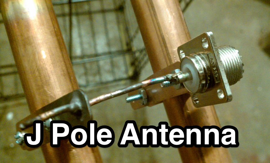 The copper J-Pole antenna soldered in a couple of hours with an interesting method to setup the feeding point
 -
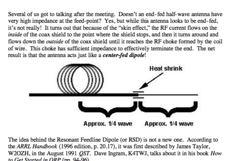 An article on RFD antennas, resonant feed-line antennas
 -
 This resource provides fundamental guidelines for optimizing mobile amateur radio antenna installations. It addresses critical factors such as achieving an adequate ground plane, minimizing common mode current, and reducing ignition noise. Specific recommendations include mounting antennas on the vehicle's roof for superior radiation patterns and utilizing proper feedline routing to mitigate RF interference within the vehicle's electrical system. The content details the impact of antenna placement on Standing Wave Ratio (SWR) and overall radiated power, emphasizing the importance of a solid electrical connection to the vehicle chassis. It also discusses strategies for noise suppression, such as bonding body panels and employing ferrite chokes on power leads. The information presented is practical for hams seeking to improve their mobile station's efficiency and reduce RF-related operational issues.
 -
 This resource details the construction of a Moxon rectangle antenna, a two-element wire beam, drawing inspiration from a _QST_ article by Allen Baker, KG4JJH, and a project group led by KD6WD. It outlines the use of _AC6LA_ software for critical measurements (A-E) to design the antenna for specific bands like 17 meters, emphasizing the simplicity of adjusting frequency and wire size. The guide covers material selection for spreaders, such as telescoping fiberglass fishing poles, and various hub constructions, including aluminum tubing and PVC joints, with accompanying images. The author shares practical insights from building multiple Moxons for 10, 15, 17, and 20 meters, noting consistent 1:1 SWR at design frequencies and broadbanded performance. It describes the feedpoint assembly using a 1:1 Yagi current balun and wire nuts for robust, adjustable connections. The resource also discusses element insulators made from Lucite strips and attachment methods to spreaders using plastic wire ties and duct tape, ensuring precise element spacing. Performance observations include significant signal improvements (4-5 S units) over quad loops and a unique "DX-Vane" effect where the suspended antenna self-aligns with the strongest DX signal. The author also recounts an unsuccessful attempt at a dual-band 17/20 meter Moxon, concluding that the Moxon is inherently a monoband antenna, supported by _EZNEC_ plots for a 17-meter design.
 -
 Wondering whether to spend a fine day with the YL or with the antenna? This article may help you decide by W1GV
 -
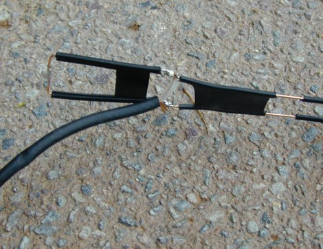 Choosing the right feed line for your antennas, is a critical decision to your station setup.
 -
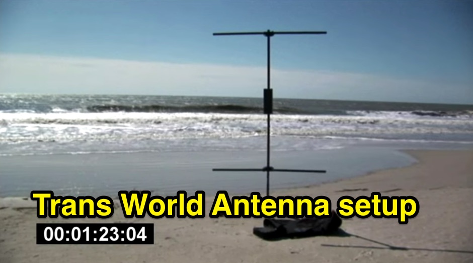 Demonstrates the swift setup process for a **Trans World Antenna**, showcasing its utility for portable amateur radio operations. The video highlights the antenna's design for quick deployment, a critical factor for activations like Summits On The Air (SOTA) or Parks On The Air (POTA), where efficiency in establishing a station is paramount. It illustrates the physical components and the sequence of assembly, emphasizing ease of use in varied field environments. The antenna system is presented as a multi-band solution, capable of operating across various HF frequencies. This adaptability makes it a versatile choice for hams engaging in outdoor activities or emergency communications. The visual demonstration provides practical insights into managing the antenna elements and feedline for optimal performance during temporary deployments. The focus remains on the practical aspects of field setup, rather than detailed technical specifications or performance metrics.
 -
 About windom antennas and OCF dipoles, tricks on covering more bands moving feed-points and potential problems. Problems caused by common mode currents in OCF dipoles
 -
 West St. Louis County Police and Fire Live Audio Feed
 -
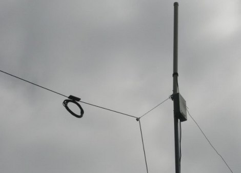 A Resonant FeeD line (RFD) antenna for 7 MHz prohect tested and tuned.
 -
 An overview of coax cable often called coaxial feeder or RF cable, used to feed antennas and deliver radio frequency power from one point to another
 -
 The _Sci.Electronics FAQ: Repair: RFI/EMI Info_ document, authored by Daniel 9V1ZV, provides a detailed analysis of computer-generated RFI/EMI, focusing on its impact on radio reception. It identifies common RFI sources such as CPU clock rates (e.g., 4.77 MHz to 80 MHz), video card oscillators (e.g., 14.316 MHz), and even keyboard microprocessors, all of which generate square-wave harmonics across HF and L-VHF regions. The resource outlines a systematic procedure for pinpointing RFI origins, including disconnecting peripherals and using a portable AM/SW receiver with a ferrite rod antenna to localize strong interference sources. The document categorizes RFI mitigation into shielding, filtering, and design problems, offering practical solutions for each. It recommends applying conductive sprays like _EMI-LAC_ or _EMV-LACK_ to plastic casings of radios, monitors, and CPUs to create effective Faraday cages, emphasizing proper grounding and avoiding short circuits. For filtering, the guide suggests using line filters, ferrite beads, and toroids on power and data lines, and small value capacitors (e.g., 0.01 uF for serial/parallel, 100 pF for video) to shunt RFI to ground. It also discusses the use of bandpass, high-pass, low-pass, and notch filters on the receiver front-end or antenna feed to combat specific in-band noise.