Search results
Query: signals
Links: 321 | Categories: 19
Categories
- Operating Modes > Amateur Television
- DX Resources > Beacons > Beacon Monitoring
- Software > Decoders
- Operating Modes > Satellites > Digital Satellites
- Software > Digital SSTV
- Software > DRM
- Technical Reference > Key Clicks
- Antennas > Lindenblad
- Propagation > Long-Delayed Echoes
- Radio Scanning > Nature
- Shopping and Services > Test equipment > Oscilloscope
- Technical Reference > Preamplifiers
- Operating Modes > QRSS
- Antennas > Quadrifilar Helix
- Technical Reference > Receiver Front-End Protector
- Software > Shortwave
- Software > Signal Generator
- Manufacturers > Test Equipment > Spectrum Analyzers
- Operating Modes > SSTV
-
 AM radio listening excels at night due to sky-wave propagation, where signals travel farther by reflecting off the ionosphere’s F1 and F2 regions. Daytime ground wave propagation falters as solar radiation ionizes the D region, absorbing signals. At night, reduced ionization allows recombination, letting waves reach hundreds of miles. This enables tuning into distant stations, like KGO in San Francisco from Northern California. Enhanced by tools like the CCRadio-2E, sky-wave propagation turns AM listening into an exciting nocturnal adventure.
 -
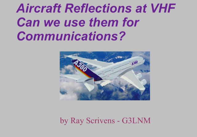 This PDF presentation explores using aircraft reflections for VHF communication. It explores the characteristics of reflected signals, including how they cause fading and vary in frequency due to aircraft movement. The feasibility of using such signals for communication is then examined. The presentation highlights challenges like requiring very narrow filters and strong frequency stability. It explores Slow-Feld, a slow version of Hellschreiber, as a potential modulation mode due to its tolerance for weak signals and frequency variations. While successful communication via aircraft reflections has been achieved, the data rate was slow and intermittent. The potential for communication over long distances, especially with busy air traffic, is discussed.
 -
 DXLog.net Cluster functions as a dedicated client application designed to enhance DXLog.net contest logging operations. It facilitates simultaneous connections to multiple DX cluster nodes, providing a consolidated view of DX spots. The software also supports integration with local CW skimmers, enabling real-time reception of CW signals and their automatic decoding into spots. The utility broadcasts UDP data across the local area network, allowing DXLog.net to receive and process these spots efficiently. A key feature includes CAT control integration, which automatically QSYs connected CW skimmers to the frequency of interest, optimizing spot acquisition. The system also incorporates duplicate spot filtering to reduce redundancy and offers blacklist management for unwanted callsigns or frequencies. Programmable commands and dynamic skimmer bandwidth control further refine its operation, adapting to varying band conditions and contest strategies. Automatic reconnection capabilities ensure continuous operation, maintaining reliable access to DX information crucial for competitive contesting.
 -
 This article explores Beverage antennas, a type used for low-frequency radio reception. Despite the mystique, they are relatively simple wire antennas placed near the ground. Their key benefit is improved signal-to-noise ratio by rejecting unwanted signals. While lengthier antennas offer better reception, even shorter versions (around 200 feet) can improve DX reception compared to traditional antennas.
 -
 Details the construction and performance of a phase-controlled receiving array, specifically a **MicroSWA** variant, optimized for QRP low band fox hunting on 40M and 80M. The resource documents the author's iterative design process, addressing significant regional noise challenges encountered during 0100-0230 UTC fox hunt periods. Initial experiments involved a director wire on a 40M vertical, yielding limited improvement, prompting a shift towards advanced null-steering techniques. The project leverages concepts from Victor Misek’s "The Beverage Antenna Handbook" and Dallas Lankford’s extensive work on phased receiving antennas for urban lots. A key modification involved integrating a new passive phase control box and a push-pull **Norton common base preamp** using 2N5109 transistors, designed for high third-order intercept performance to maintain weak signal integrity amidst strong adjacent signals. The system incorporates Faraday-shielded transformers with RG174 primaries on -75 ferrite cores, housed in ABS plastic pipe. Performance tests confirmed the MicroSWA's ability to produce deep, steerable nulls, achieving approximately 30 dB noise reduction on 160M, 80M, and 40M. This enabled detection of QRP signals undetectable on conventional transmit antennas. The final unit includes front panel controls, a 10-11 dB preamp, and a robust power conditioner, demonstrating effective noise mitigation for challenging low band QRP operations.
 -
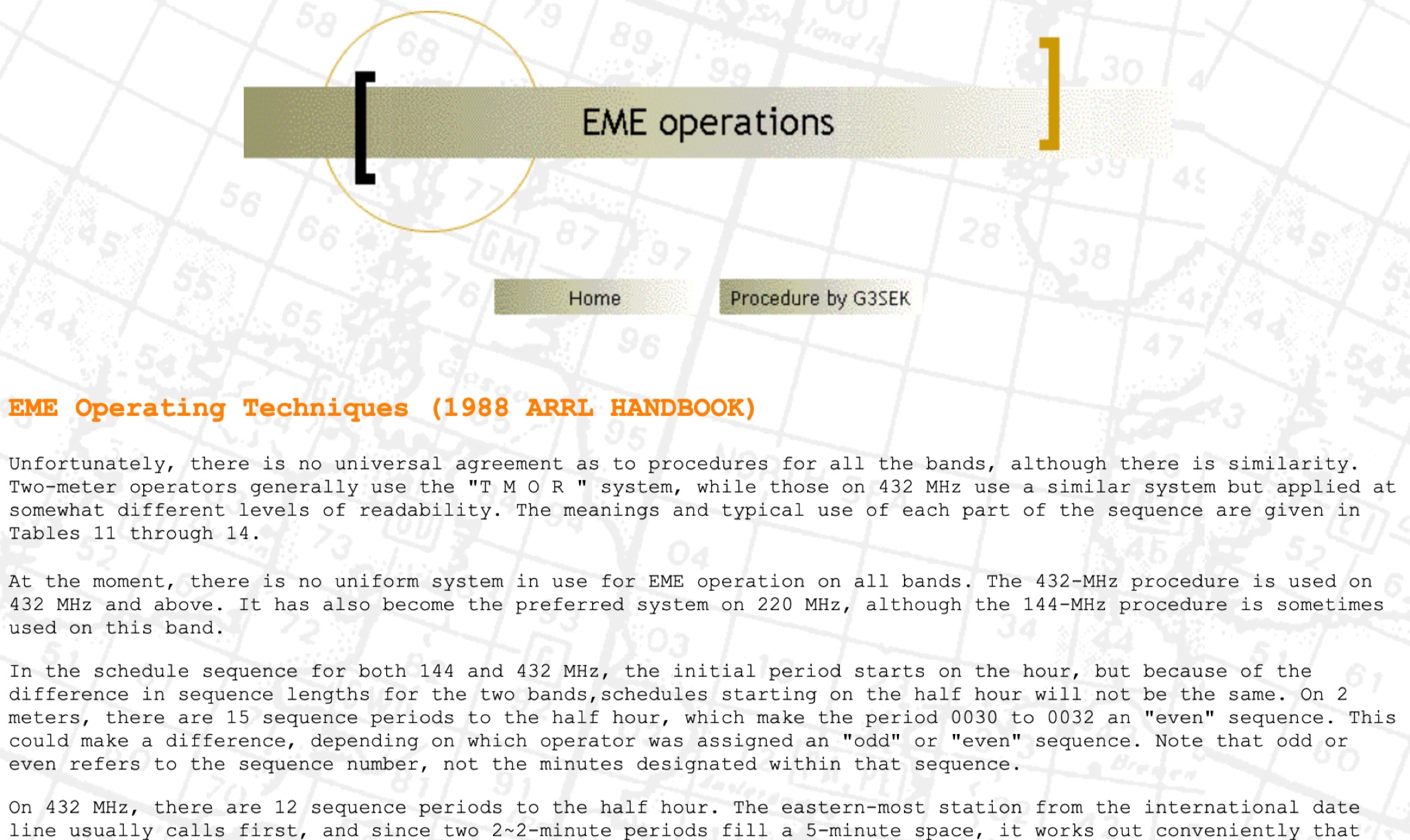 This resource provides an in-depth look at Earth-Moon-Earth (EME) operating techniques specifically for the 432 MHz band and above. It outlines the differences in operational procedures between the 144 MHz and 432 MHz bands, emphasizing the importance of sequence lengths and scheduling. The initial calling period typically starts on the hour, with the eastern-most station calling first, which is crucial for effective communication. The document also discusses the challenges faced by operators, such as signal readability and the necessity of confirming exchanges. It highlights the significance of using a standardized procedure to enhance the likelihood of successful contacts. Additionally, it covers the use of signal reports and the importance of patience and clarity in communication, especially when dealing with weak signals. Overall, this guide serves as a valuable resource for amateur radio operators interested in improving their EME operations.
 -
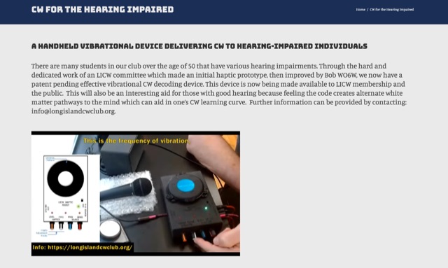 The resource details a novel approach to Morse code (CW) reception for hearing-impaired operators, focusing on a handheld device that translates CW signals into tactile vibrations. It explains how this device allows users to perceive the patterns of dots and dashes through physical feedback from a shaker, addressing the challenges of auditory discrimination for those with hearing loss. The content highlights the potential for this tactile method to aid in CW learning and interpretation, even suggesting benefits for operators with normal hearing by providing an alternative sensory input. The article also mentions the device's _patent-pending_ status and its availability to members of the _Long Island CW Club_ and the general public. It provides contact information for further inquiries about this innovative tool.
 -
 Assessing the ICOM IC-R9000 communications receiver, this review details its operational parameters and user experience for radio enthusiasts. Introduced in 1985, the IC-R9000 covers a broad frequency spectrum from 0.1 MHz to 1999.8 MHz, making it suitable for a wide array of listening activities from medium wave (MW) to VHF/UHF. Key performance metrics include a dynamic range of **102 dB** with the narrow SSB filter, crucial for discerning weak signals in crowded bands, and its substantial physical dimensions of 424 x 150 x 365 mm and 20 kg weight. The receiver's architecture supports various modes, though it notably lacks synchronous detection, a feature often desired for improved AM reception under fading conditions. It incorporates 1000 memory channels and robust scanning capabilities, facilitating efficient monitoring across its extensive frequency range. This analysis provides insights into the IC-R9000's capabilities and limitations, offering a historical perspective on a significant piece of amateur radio and shortwave listening hardware.
 -
 This page by ARCTICPEAK provides a calculator for determining ERP and EIRP (Effective radiated power and effective isotropic radiated power). The tool is designed to help hams calculate and understand the power radiated by their radio equipment. The content is useful for ham radio operators who want to optimize their transmission power and comply with regulations. LA8OKA Martin has created this resource to assist hams in accurately measuring their radio signals.
 -
 The Olivia digital mode, a **Multi-Frequency Shift Keying (MFSK)** radioteletype protocol, is specifically engineered for robust communication under difficult propagation conditions on shortwave radio bands from 3 MHz to 30 MHz. Developed by Pawel Jalocha in 2003, Olivia signals can be decoded even when the noise amplitude exceeds the digital signal by over ten times, making it highly effective for transmitting ASCII characters across noisy channels with significant fading and propagation phasing. Early on-the-air tests by Fred OH/DK4ZC and Les VK2DSG on the Europe-Australia 20-meter path demonstrated intercontinental contacts with as little as one-watt RF power under favorable conditions. Common Olivia modes are designated as X/Y, where X represents the number of tones and Y is the bandwidth in Hertz, with examples including 8/250, 16/500, and 32/1000. The resource clarifies that Olivia, unlike some other digital modes, produces a constant envelope, allowing RF power amplifiers to achieve greater conversion efficiencies and making it less prone to non-linearity. Operators are advised that **Automatic Level Control (ALC)** can be set higher than no meter movement for MFSK modulation, as long as it's not driven past its high limit, contrary to common misinformation about other digital modes. The Olivia community encourages voluntary channelization on suggested calling frequencies, such as 14.0725 MHz for 8/250, to facilitate initial contacts, especially for signals below the noise floor. The Olivia Digital DXers Club provides links to Groups.io, Facebook, and Discord for community engagement and offers details on QSO parties.
 -
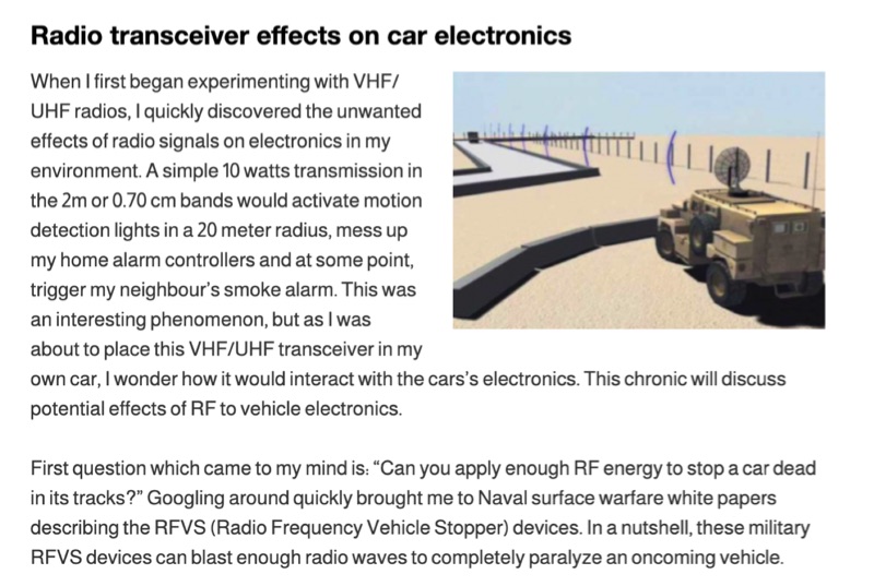 Illustrates the potential for radio frequency (RF) energy from amateur transceivers to interfere with vehicle electronics, drawing parallels to military _Radio Frequency Vehicle Stopper_ (RFVS) technology. The resource details personal experiences with VHF/UHF signals activating household devices and then pivots to the complexities of RF interaction with automotive systems, noting the development of multi-frequency RFVS (MFRFVS) to overcome vehicle-specific vulnerabilities. It highlights that while car manufacturers conduct RF immunity tests, the rigor varies, with luxury brands likely performing more extensive evaluations than others who merely meet minimal certification. The article explores practical considerations for mobile amateur radio installations, suggesting antenna placement over the car, using lower power output, and proper grounding to mitigate adverse effects. It acknowledges the lack of comprehensive data on RF/vehicle combinations but emphasizes that adherence to these basic principles can reduce risks. The author shares observations of unexplained car computer codes in a 2002 SUV, speculating on potential RF induction. Concerns are raised about the increasing complexity and interconnectedness of modern car electronics, including Bluetooth, remote access, and electronic control systems for critical functions like steering and braking. The article points out the diminishing space for third-party installations in contemporary vehicles and references the ARRL's stance on auto manufacturer policies regarding amateur radio installations, which generally advise against them.
 -
 The **Yaesu FRG-100** shortwave receiver, introduced in 1992, operates across a frequency range of 50 kHz to 30 MHz, accommodating AM, LSB, USB, and CW modes, with an optional narrow-band FM capability. Its physical dimensions are 238 x 93 x 243 mm, with a weight of 3 kg, making it suitable for both portable and fixed station deployments. Power options include standard mains voltage or 12VDC, providing operational flexibility for diverse listening environments. The front panel integrates a manual tuning knob, an analogue signal strength meter, and an LCD display that provides critical information such as frequency, operating mode, memory channel, and time. Users can configure various operational parameters, including tuning steps and bandwidth filters, to optimize reception for specific signals. This review highlights the FRG-100's straightforward interface and its utility for shortwave listening enthusiasts. The design emphasizes user-friendly adjustments for settings, which contributes to its appeal among those interested in general coverage reception.
 -
 The Pressure Paddle V2.0 simplifies the original 2019 design by using MOSFETs’ unique properties for reliable, minimalistic switching. When pressure sensors detect a press, they reduce resistance, activating the MOSFET and lowering voltage until it stabilizes at the MOSFET’s threshold. This ensures consistent “key down†signals for the transceiver. Compatible with 3-5V logic systems, the circuit operates independently of pull-up resistor size. The PCB is lightweight, easy to assemble, and can be packaged in heat shrink or mounted. This version maintains durability with fewer components and flexible packaging options.
 -
 Tracing the foundational work of Guglielmo Marconi, this article details his early laboratory experiments in 1895, where he successfully transmitted wireless signals over 1.5 miles. It highlights his 1896 patent for a wireless telegraphy system in England and subsequent demonstrations, including signal transmissions up to 6.4 km (4 miles) on Salisbury Plain and nearly 14.5 km (9 miles) across the Bristol Channel. Marconi's work built upon the mathematical theories of _James Clerk Maxwell_ and the experimental results of _Heinrich Hertz_, proving the practical feasibility of radio communication. The resource further chronicles the formation of The Wireless Telegraph & Signal Company Limited in 1897 and Marconi's relentless efforts to popularize radiotelegraphy. A significant milestone was the 1901 transatlantic reception of the Morse code letter "S" from Poldhu, Cornwall, at St. John's, Newfoundland, using a kite-supported wire antenna, defying contemporary mathematical predictions about Earth's curvature limiting range. This achievement underscored the global potential of radio. The article also touches upon Marconi's later discoveries, such as the "daytime effect" concerning atmospheric reflection of radio waves, and his 1902 patent for a magnetic detector, which became a standard wireless receiver. His contributions earned him a Nobel Prize in 1909.
 -
 SAT filters ensure effective full-duplex satellite QSOs by mitigating interference between 145 MHz uplink and 435 MHz downlink signals. Custom coaxial and SMD-based filters address transmitter harmonic interference and improve receiver isolation, achieving over 70 dB suppression in the undesired band. Designed for simplicity, these filters maintain optimal VSWR and are housed in shielded brass enclosures. Practical implementations with Yagi antennas demonstrate compatibility with SDR systems, enabling seamless communication even in challenging satellite conditions, such as low-elevation passes and DX pile-ups.
 -
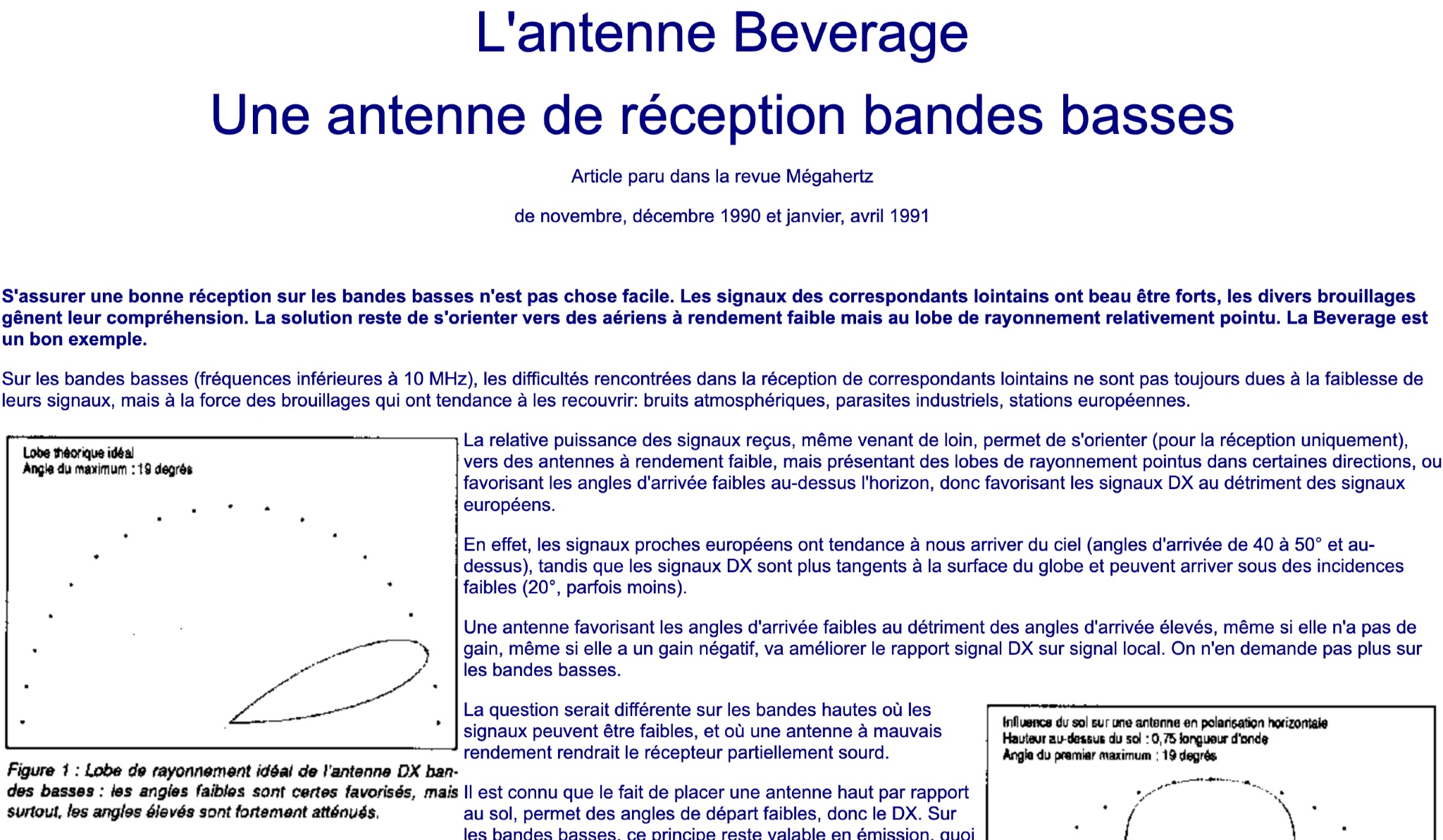 This article discusses the Beverage antenna, a reception antenna for low bands, originally published in the Megahertz magazine between November 1990 and April 1991. It explains the challenges faced in receiving signals on low bands due to interference and how the Beverage antenna's directional radiation pattern can help improve reception of distant stations. The article highlights the importance of choosing antennas with low efficiency but sharp radiation lobes for better DX signal reception. It also compares the reception characteristics of signals from European stations versus DX stations, emphasizing the benefits of antennas favoring low arrival angles for DX signals on low bands.
 -
 Early 20th-century transatlantic wireless communication efforts involved distinct technical approaches by Reginald Fessenden and Guglielmo Marconi. Marconi's systems, operational until approximately 1912, primarily utilized _spark technology_ for wireless telegraphy, facilitating Morse code communication between ships and across oceans. His Poldhu station in December 1901 radiated signals in the MF band around 850 kHz, later evolving to 272 kHz in October 1902, and eventually 45 kHz by late 1907 with increasingly larger antenna structures like the pyramidal monopole and capacitive top-loaded arrays. Fessenden, conversely, focused on _continuous wave transmission_ for wireless telephony, recognizing its necessity for speech. His transatlantic experiments in 1906 employed synchronous rotary-spark-gap transmitters and 420-foot umbrella top-loaded antennas at Brant Rock, MA, and Machrihanish, Scotland, tuned to approximately 80 kHz. Fessenden later utilized the _Alexanderson HF alternator_ at 75 kHz by late 1906 for pure CW transmission, integrating a carbon microphone for amplitude modulation. Receiver technology also differed, with Marconi initially relying on untuned coherer-type detectors, later developing the magnetic detector in 1902, while Fessenden's CW approach necessitated more advanced detection methods.
 -
 Demonstrates the construction of an active loop converter specifically designed for the Low Frequency (LF) bands, addressing common localized noise interference in LF reception. The design integrates a sharply tuned circuit and a tuned loop antenna, utilizing the loop as the sole tuned inductive element. By applying positive feedback, the converter significantly increases the loop's effective Q, achieving factors between 1000 and 2000, which sharpens tuning and reduces noise. The circuit employs an _NE602_ mixer stage, feeding its output to an HF receiver, with a crystal-locked local oscillator at 4 MHz. A 20-turn, 0.8-meter square loop antenna with 500 uH inductance is detailed, connected via 2 meters of figure 8 flex cable. The converter offers three selectable frequency bands: 195-490 kHz, 150-220 kHz (including the New Zealand amateur band), and 128-160 kHz (covering the European amateur band). Performance measurements indicate an effective 3dB bandwidth of approximately 100 to 200 hertz at 200 kHz. The article provides insights into component selection, including an _LF353_ op-amp and a trifilar wound transformer on a ferrite core. Sensitivity figures are presented, showing 7.5 uV of converted output per 1 uV/meter signal strength into a 50-ohm load, or 37.5 uV into an _FRG7_ receiver, highlighting its capability to extract weak signals from noise.
 -
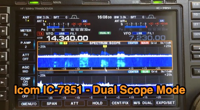 The Icom IC-7851 features the capability to display two scopes simultaneously, providing frequency, mode, and antenna information for each receiver. Users can choose between vertical or horizontal display orientations, and the dual scopes are also viewable on a high-resolution monitor connected to the radio. Additionally, the IC-7851 allows for mouse connectivity, enabling users to click on signals displayed on either scope for quick tuning. A demonstration video is available showcasing this dual scope functionality.
 -
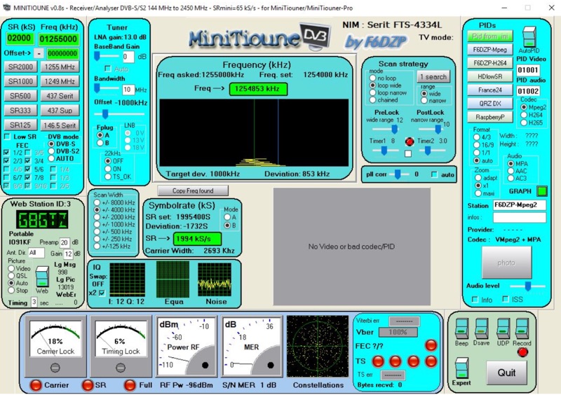 Receiving Digital Amateur Television (DATV) signals requires specialized software to interface with hardware tuners and decode the video stream. The _MiniTioune_ software, developed by F6DZP, serves this purpose, providing a Windows-based application for DVB-S and DVB-S2 reception and analysis. It is designed to work in conjunction with _MiniTiouner_ hardware, enabling hams to monitor DATV transmissions, including those from the QO-100 geostationary satellite. The resource outlines the initial setup process, including connecting the MiniTiouner hardware via a high-quality USB2 mini cable and running diagnostic test software. It details how to configure essential parameters such as symbol rate (SR), FEC rate, and DVB mode for various signal sources, from domestic satellite dishes to local DATV transmitters. Troubleshooting steps for common issues like "no video displayed" are also provided, often pointing to corrupted software filters or incorrect _Auto PID_ settings. Advanced features like the Web monitor for remote signal reporting and integration with _VLC_ media player for more tolerant decoding of non-DVB compliant signals are covered. The document also references a comprehensive user guide by W6HHC for the _MiniTiouner-Express_ system, which utilizes the same software, offering further in-depth assistance for operators.
 -
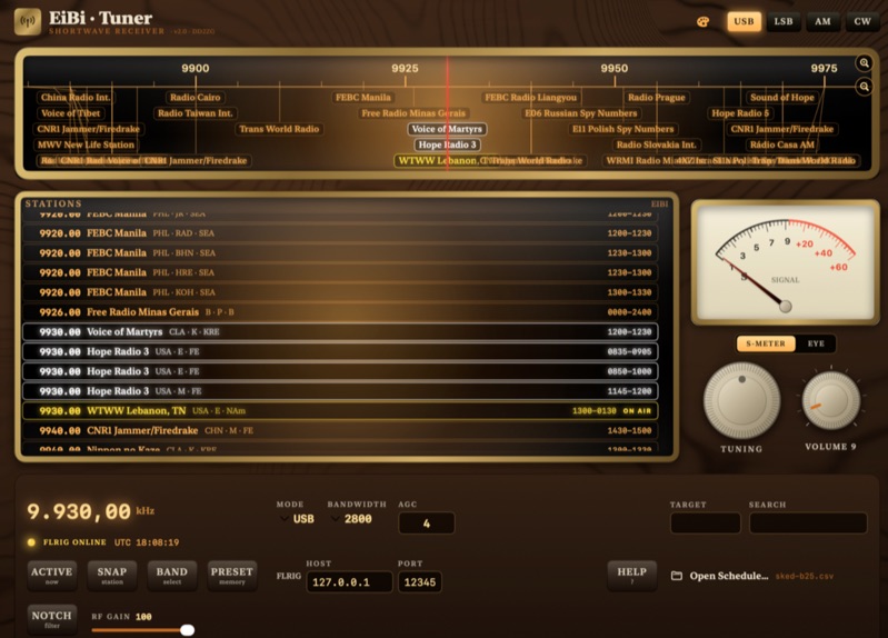 EiBi-Tuner-v2 is an open-source macOS application designed to control amateur radio transceivers via the FLRIG interface, leveraging the EiBi-list for frequency management. This software provides a graphical user interface that emulates an older radio, allowing operators to tune their rigs based on the extensive EiBi database of broadcast stations and utility frequencies. The application is specifically compiled for macOS, offering a native experience for users of Apple's desktop operating system. The software's primary function is to simplify frequency selection and rig control by integrating the EiBi-list, which contains thousands of known frequencies, with FLRIG's robust transceiver control capabilities. This integration allows for rapid QSY to documented frequencies, potentially enhancing DXing and SWL activities by providing quick access to a vast array of signals. The open-source nature permits community contributions and modifications, ensuring adaptability and ongoing development for specific amateur radio operational needs.