Search results
Query: Receiver
Links: 509 | Categories: 36
Categories
- Internet and Radio > Online Receivers
- Technical Reference > Receivers > Progressive Receiver
- Technical Reference > Receiver Front-End Protector
- Manufacturers > Receivers
- Radio Equipment > Receivers
- Technical Reference > Receivers
- Technical Reference > Receivers > Regenerative Receiver
- Shopping and Services > Amateur Television
- Technical Reference > Receivers > Crystal radio
- Radio Equipment > Receivers > Drake R-4B
- Radio Equipment > Receivers > Drake R-4C
- Manufacturers > Filters
- Technical Reference > Headsets and Speakers
- Technical Reference > HF Radios
- Manufacturers > Transceivers > Icom
- Radio Equipment > Receivers > Icom IC-R20
- Radio Equipment > Receivers > Icom IC-R7100
- Radio Equipment > Receivers > Icom IC-R75
- Internet and Radio > Live streaming
- Software > Radio Control
- Operating Modes > Radio Direction Finding
- Technical Reference > Radio Direction Finding
- Radio Equipment
- Technical Reference > Radio Mods
- Software > Radio Programming
- Radio Scanning
- Radio Equipment > Reviews and Comparisons
- Technical Reference > RF Design
- Technical Reference > Scanners
- Manufacturers > Scanners
-
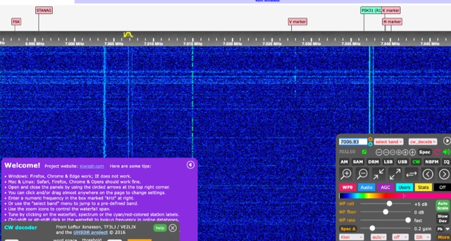 KiwiSDR Software-defined receiver at Bjargtangar Iceland covering HF Bands
 -
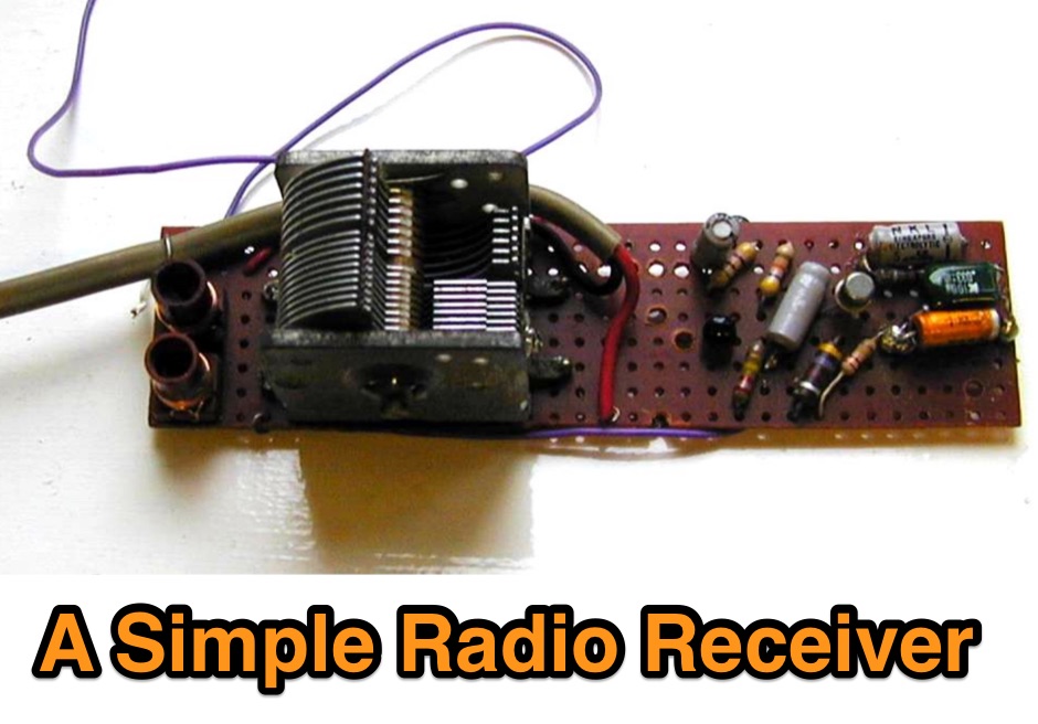 A very simple experimental short wave radio receiver. This is basically just a crystal radio with two stages of transistor amplification afterwards made with scrap components.
 -
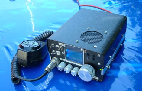 This article describes the construction of a high performance transmitter and receiver for SSB (voice) communication covering the 14MHz (20 meters) high frequency amateur radio band with output range 15 to 20 watts and a top audio sound quality both on transmit and receive.
 -
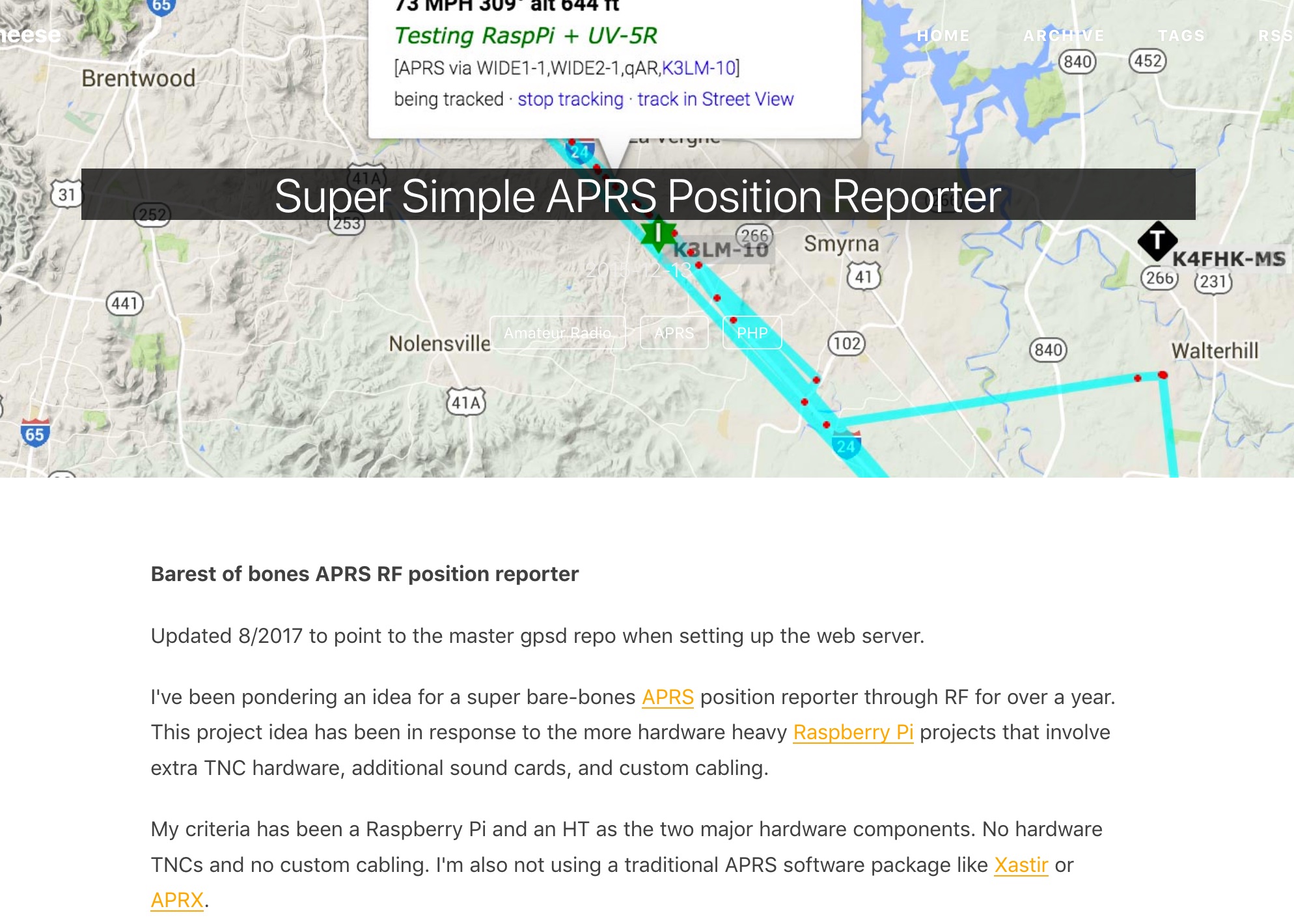 Barest of bones APRS RF position reporter using a Raspberry Pi B+, USB GPS receiver, Baofeng UV-5R, and a mono 3.5mm audio cable between the Pi and the radio
 -
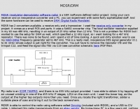 An SDR project, MDSR modulator-demodulator software radio, made using an inexpensive converter and a pc. MDSR has a transceiver and a receiver converters.
 -
 Producers of custom name tags, luggage tags, club badges, Employee Name Tags, Special Event Badges, but also Comtech Amateur Radio Television Transmitters and Receivers D480 filters, Video cameras and accessories.
 -
 Receivers and transmitters by Collins , Drake , Hallicrafters , Hammarlund , National Receivers
 -
-
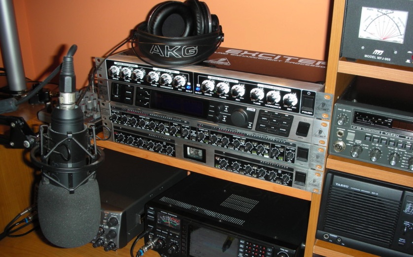 Sending the Audio from the Receiver to the Recorder, from the Recorder to the EQ, and sending the Audio from the EQ or Recorder to the Transmitter
 -

-
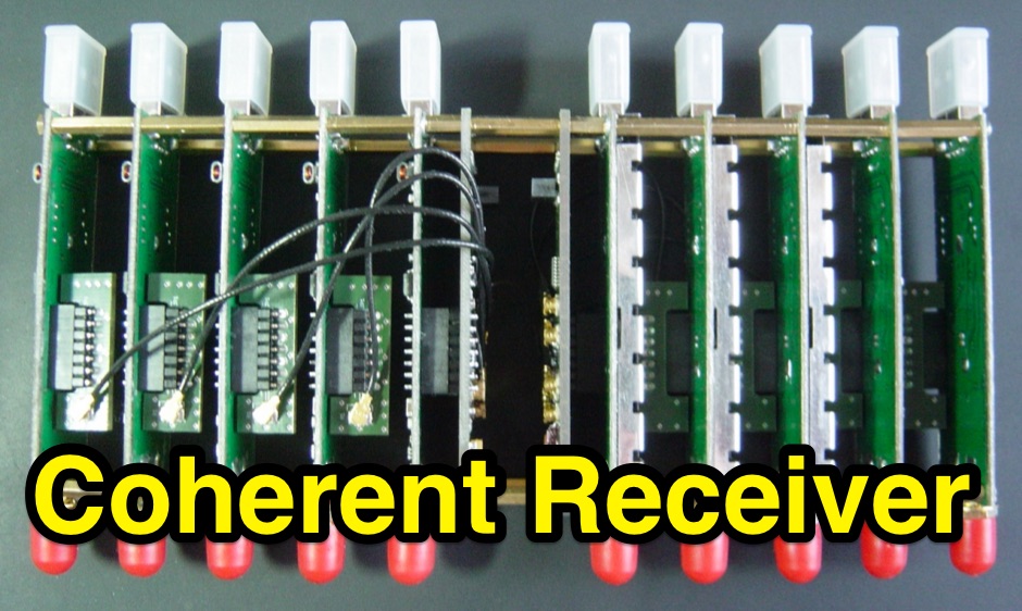 N-channel scalable coherent receiver that employs the RTL-SDR technology in order to create inexpensive multi-channel receiving systems.
 -
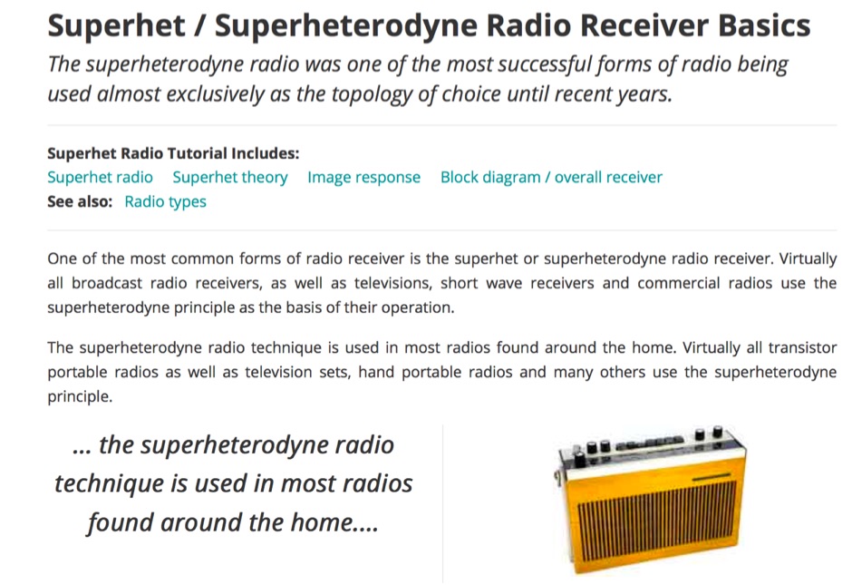 Key details about the superhet or superheterodyne radio reeiver: basic overview; how it works; applications; design notes, all you need to know.
 -
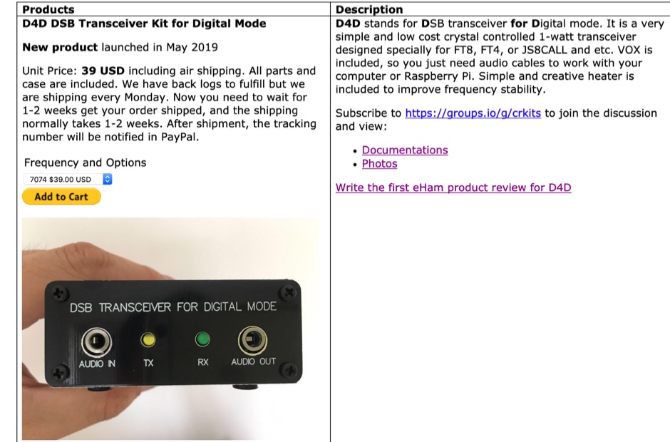 Since 2011, crkits offer radio kits that you cannot find on eBay or AliExpress. Includes HT-1A 20/40m Dual Band CW Transceiver Kit, D4D DSB Transceiver Kit for Digital Mode, R3500D ARDF Receiver, CW Transceiver Kit
 -
 Vintage radio and scientific apparatus by john jenkins, include antique radios, Horn Loudspeakers, Vacuum Tubes, A.C. Receivers
 -
 A 0-30 MHz step attenuator, constructed from switchable Pi attenuation pads, provides a practical tool for evaluating receiver sensitivity and calibrating S-meters. The design utilizes readily available 5% tolerance resistors, with values derived from paralleled components to achieve specific attenuation steps. A schematic (Fig 1) illustrates the circuit, including PCB pad shielding, while a table details required and actual resistor values, along with percentage differences. Measurements of voltage input versus output at various frequencies are used to calculate dB attenuation, presented in a graph (Fig 4). The resource includes formulas for determining output voltage from a known input and a comprehensive 0-40 dB voltage multiplier table, which is crucial for precise signal level management. The project also references external attenuator calculators and equations for further study. Photos (1-3) provide visual guidance for the assembled unit, showing bottom, top, and front views. The project emphasizes the use of **Pi attenuation pads** and **receiver sensitivity** evaluation, offering a hands-on approach to RF signal management.
 -
 How to build a complete Single-Sideband amateur radio transceiver from scratch. Article published on hackaday dot com includes an introduction to radio architectures, ssb receivers and tramsitter
 -
 Presented is a historical collection of short-wave listening (SWL) QSL cards, primarily from the late 1930s and early 1940s, offering a glimpse into early international broadcasting and the technical pursuits of SWL operators like Les Miles during that era. The resource showcases specific QSLs from stations such as _Broadcasting Corporation of Japan_, _XGOY - The Central Broadcasting Administration_ in Chungking, China, and _Australian broadcasting ship, Kanimbla VK9MI_, each with reception dates and frequencies like 11.90MHz or 9.525MHz. It highlights the self-sufficiency of SWL enthusiasts who constructed and maintained their own radio and test equipment, evoking the sensory experience of vintage valve receivers. The collection provides concrete examples of international broadcast stations active before and during World War II, including _2RO3 - Rome_ and _WRUL - World Wide Broadcasting Foundation_ from Boston. Each QSL entry details the station, location, reception date, and often the frequency, such as 9.63MHz or 11.26MHz, allowing for historical verification of broadcast schedules. The resource also briefly mentions the operational details of the _VK9MI_ offshore radio station, directing readers to further information on its history. This compilation serves as a tangible record of global radio communication during a pivotal historical period.
 -
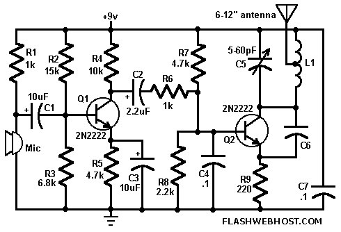 This FM wireless mike can transmit voice signals to any FM Radio receiver 100 meters away.
 -
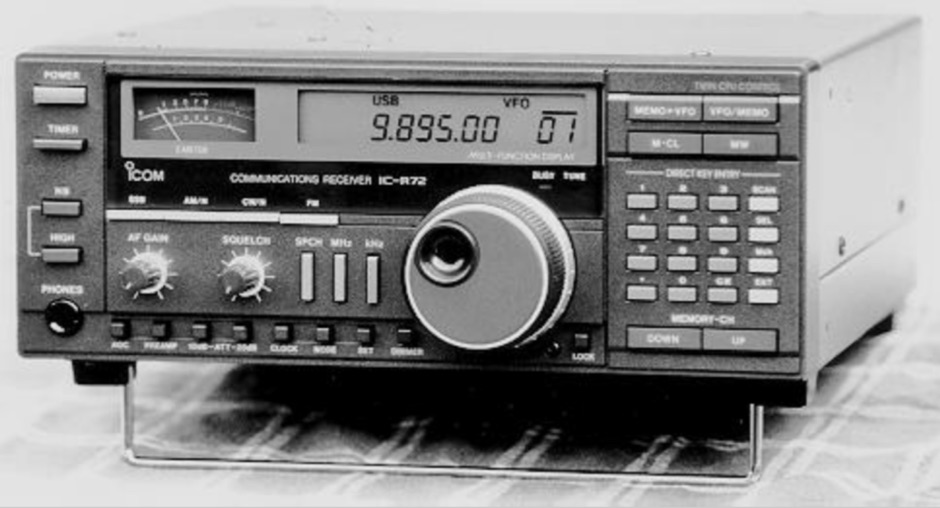 The ICOM IC-R72E a neat compact communications receiver. Coverage: LW, MW, SW (0.1- 30.0 MHz continuous) discontinued in 1998
 -
 Low-frequency (LF) radio time signals, operating primarily in the 40–80 kHz range, are broadcast by national physics laboratories for precise clock synchronization. Transmitters like **JJY** (40 kHz, 50 kW; 60 kHz, 50 kW), RTZ (50 kHz, 10 kW ERP), MSF (60 kHz, 15 kW ERP), WWVB (60 kHz, 50 kW ERP), RBU (66.66 kHz, 10 kW), and DCF77 (77.5 kHz, 50 kW) cover vast geographic areas, often several hundred to thousands of kilometers. LF signals offer distinct propagation advantages over higher-band transmissions such as GPS. Their long wavelengths (3–6 km) enable effective diffraction around obstacles like mountains and buildings. The ionosphere and ground act as a waveguide, eliminating the need for line-of-sight and allowing a single powerful station to cover extensive regions. Ground wave propagation minimizes ionospheric variability effects on transmission delay, and signals penetrate most building walls effectively. Robust and low-cost receivers, often priced at 20–30 USD/EUR, are widely used in radio clocks. These receivers typically comprise a tuned ferrite core antenna, a receiver IC (e.g., Atmel T4227, U4223B, MAS1016) for amplification and AM detection, and a microcontroller for decoding the time signal and phase-locking a local clock. Specific components for DCF77, MSF, and WWVB are readily available from vendors like HKW Elektronik and Ultralink.
 -
-
 On December 12, 1901, Guglielmo Marconi successfully received the first transatlantic wireless communication, a Morse code "S" (three dots), at 04:30 GMT. This article details the setup for this groundbreaking experiment, noting Marconi's receiver in St. John’s, Newfoundland, Canada, utilized a _coherer_ and an antenna elevated by balloons and kites. The transmitting station at Poldhu, Cornwall, England, featured twenty-four 200-foot ships' masts and a 25-kilowatt alternator. The resource explains how this contact disproved contemporary beliefs about radio wave limitations due to Earth's curvature, later understood through _ionospheric propagation_. It frames Marconi's achievement as the "very first DX" in amateur radio terms, defining DX as telegraphic shorthand for distance and _DXing_ as the hobby of receiving distant signals. The article also provides external links for further reading on Marconi's experiments and the science behind transatlantic radio signal reception.
 -
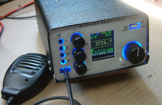 Gimme Five reloaded, a compact 5 band QRP SSB transceiver in SMD technology. This unit covers 5 bands within the amateur radio spectrum (3.5, 7, 14, 21 and 28 MHz). Receiver is a single conversion unit with an interfrequency of 9 MHz. Transmitter uses 5 stages and has got a power level of 10 watts PEP output.
 -
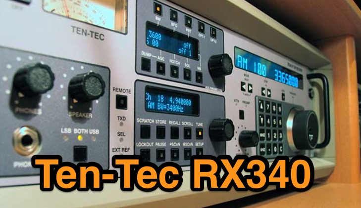 A complete review of the Ten-Tec RX340 all mode HF receiver
 -
 Amateur Packet Reporting System (APRS) operations often require compact, reliable solutions for transmitting position data, particularly for mobile or portable stations. This resource details the construction of the _Tiny Track-I_, a transmit-only APRS tracker designed for straightforward integration with a VHF radio and a Global Positioning System (GPS) receiver. It enables hams to broadcast their location without the complexity of a full-duplex TNC. The project outlines the printed circuit board (PCB) layout and schematic, based on an original design by N6BG, with a personal PCB drawing by SV1BSX. It includes specific component placement and notes an additional 10uF/10V capacitor (C5) for improved IC voltage decoupling, a modification not present in the original N6BG diagram. The unit connects to a computer or GPS via a DB9 female connector. This tracker is ideal for basic position reporting, offering a simple and effective way to participate in APRS networks. Its small footprint makes it suitable for vehicle installations or field deployments where space is limited, providing a **reliable 9600 baud** data stream for location updates.
 -
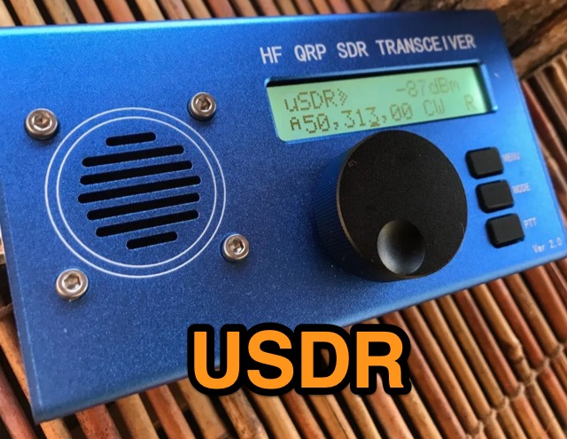 A review of the Chinese version of uSDX USDR HF QRP Transceiver. Author made an extensive review of receiver and transmitter features.
 -
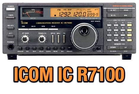 VHF-UHF receiver covers from 25 to 800 and 900 to 2000 MHz in the following modes: AM, AM-W, FM, FM-W, FM-N, USB and LSB
 -
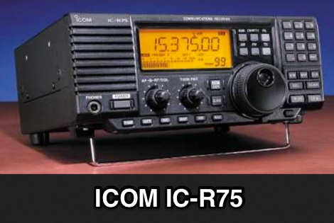 A detailed review of the Icom IC-R75 30 kHz -6 0 MHz Receiver first introduced in 1999
 -
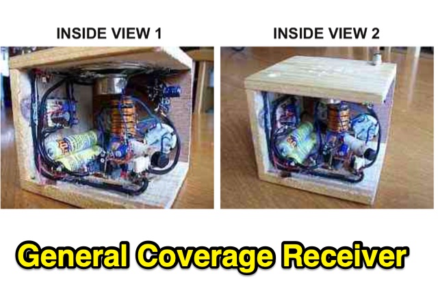 This is a compact three transistor regenerative general coverage receiver with fixed feedback. The sensitivity and selectivity is relative good, especially on the LF and MW bands, as can be expected with this simple design.
 -
 Homemade receiver for 80 meters band. The receiver works very well (in fact better than some of its successors), especially the AGC makes listening to 80m QSOs a real pleasure. Sensitivity is not cutting-edge, but on a full-size short-wave antenna it is by fare sensitive enough.
 -
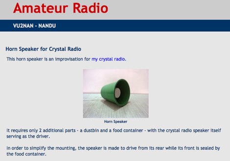 Homebrew Antennas, Transmitters, Receivers, Converters, Keyers and SWR/RF Current Indicators with photographs an excellent blog with many projects by VU2NAN
 -
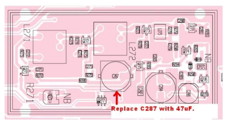 If your 756 has lots of noise with crackles and sweeping heterodynes, especially noticeable on AM, it may be due to a faulty electrolytic capacitor in the noise-blanker circuit
 -
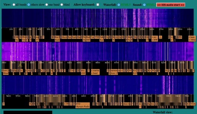 WebSDR receiver located near Krizevci, Croatia with 0-2 MHz, 60-80 meters band and 40-49 meters band
 -
 Manufacturer of software definded radio receivers, antenna switches, preselectors, antenna splitters based in Italy and USA
 -
 Operating in a Single Operator Two Radios (SO2R) setup, especially with beverage antennas, often exposes the receiving radio's front-end to significant RF energy from the transmitting radio. This resource details a practical, homebrew receiver protection circuit designed to mitigate this risk. The core of the design involves a non-inductive 2W 22 Ohm carbon composition resistor in series with the RX antenna line, followed by two stacks of four fast-switching diodes (e.g., _1N914_) configured in opposite polarizations. This arrangement effectively clamps the incoming voltage to approximately 2.8 V peak-to-peak, safeguarding sensitive receiver input components. The series resistor plays a crucial role by absorbing excess power, preventing the diodes from exceeding their current ratings and potentially failing open, which would leave the receiver unprotected. The author, _N4KG_, measured up to 50 watts of coupled power between 80M slopers on the same tower, highlighting the necessity of such protection. The design is presented as a cost-effective solution to prevent damage to receiver input transformers, with the author noting successful protection of a receiver even after a resistor showed signs of overheating. This simple circuit can be integrated via a transverter plug, offering a robust defense against high RF input.
 -
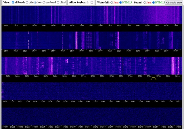 This is a WebSDR receiver, located in Friedrichshafen, Germany (at Lake Constance) using a multiband dipol and a FUNCube Dongle Pro+.
 -
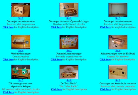 Crystal receivers are radio receivers that work without a power supply or batteries. Gallery of some crystal radio projects
 -
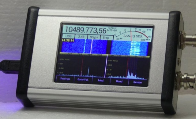 Stand Alone Software Defined Radio, direct sampling receiver from 30 kHz to 1700.00MHz continuous frequency range, LAN interface for remote access
 -
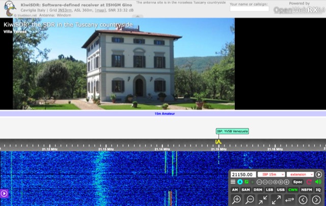 A software defined receiver located in Tuscany Italy with a Windom antenna convering HF bands
 -
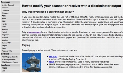 How to modify your scanner or receiver with a discriminator output. If you want to decode and monitor digital (FSK and PSK) systems seriously, a discriminator tap is an absolute prerequisite.
 -
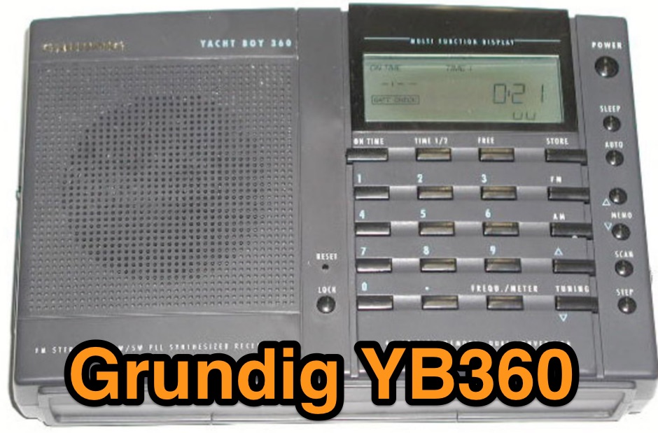 An independent review of the Grundig Yacht Boy 360 portable mediumwave receiver
 -
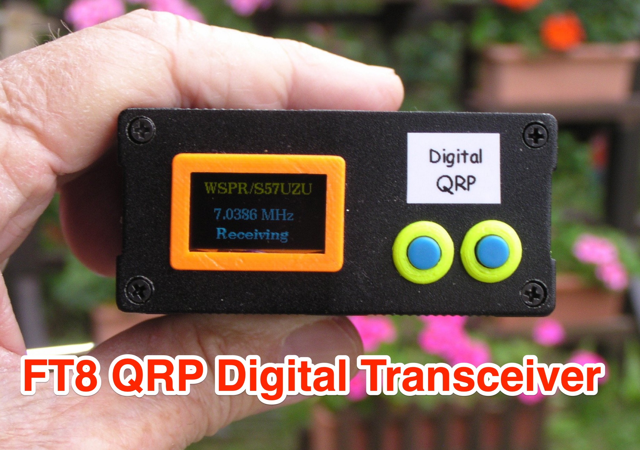 Learn how to build a QRP digital transceiver with Arduino, based on a project by Burkhard Kainka. This article covers the development process, including the source code, modifications made, and the addition of an OLED display for a more professional look. Discover the inner workings of the transceiver, from the receiver to the oscillator, and how components like the CD2003 are utilized. Explore the schematic design, the use of a PLL module Si5351A controlled by Arduino nano, and more. Ideal for hams looking to create their own digital transceiver for amateur radio operations.
 -
 Mitigating impulse-type noise, a common challenge in the **HF radio spectrum**, often requires specialized processing before the signal reaches the transceiver's receiver stages. The NR-1 addresses this by functioning as an RF interference removal device, specifically a noise blanker, targeting transient noise sources. Its operational range extends from 1.6 MHz to beyond 70 MHz, making it suitable for various amateur radio bands and general shortwave listening applications. Unlike QRM eliminators or X-phasers, the NR-1 does not require a separate noise antenna for its operation, simplifying its integration into existing station setups. The device's design focuses on wideband performance, allowing its use both within and outside the allocated amateur radio frequencies. Documentation detailing its operation is available, providing insights into its technical specifications and deployment. This unit is a hardware product, conceptualized and implemented by SV3ORA.
 -
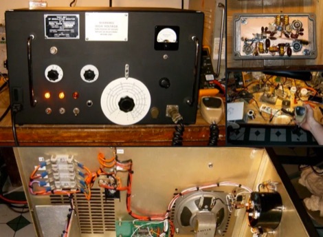
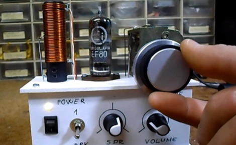 The build was an experiment to see if a tube receiver could be stable enough to receive digital shortwave radio broadcasts. The tube acts as both an oscillator and mixer, so the receiver is a type of direct conversion receiver.
 -
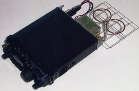 A very small receiver converter that can be plugged to the backside of the battery powered portable transceiver FT817 from Yaesu. A high performance receiver for 2.3GHz amateur radio signal
 -
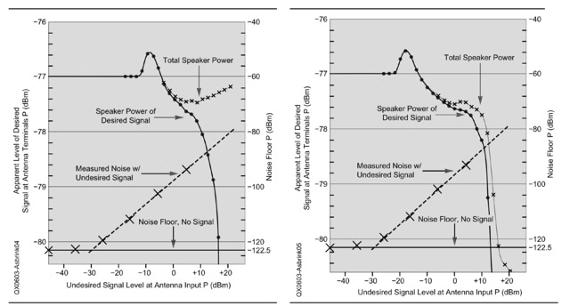 An explanation of the different procedures and definitions that are commonly used for blocking dynamic range (BDR) measurements. Dynamic range in general is the ratio between the weakest signal a system can handle and the strongest signal the same system can handle simultaneously without an operator switching attenuators or turning volume potentiometers
 -
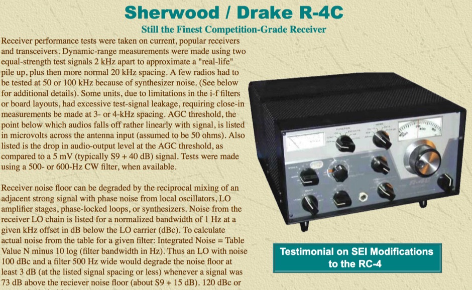 Filters and replacement parts for the Drake R-4C receiver by Sherwood Engineering Inc
 -
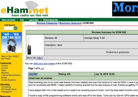 eHam.net reviews of the Icom IC-R20 wideband receiver
 -
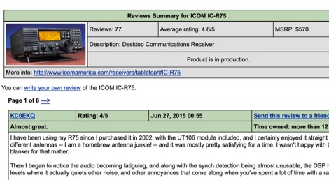 eHam users review of the Icom IC-R75 receiver
 -
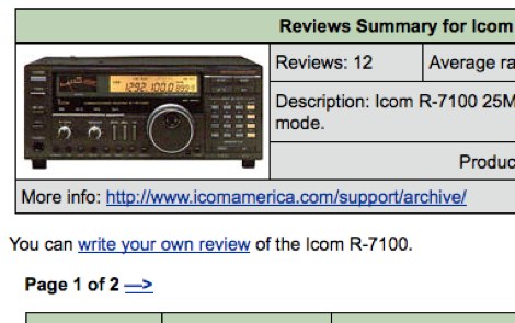 eHam reviews of the Icom IC R7100 VHF UHF receiver