Search results
Query: antenna 2 meters
Links: 672 | Categories: 9
-
 A magnetic loop antenna working from 30 to 15 meters with 100W
 -
 An homemade fan dipole antenna for 20 30 40 meter bands, setup in a 15 meter wide garden. The longest leg for 40 meter is folded to fit in the 7.5 m
 -
-
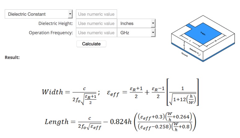 Microstrip Patch Antenna Calculator determines the length and width in millimeters of a rectangular patch antenna.
 -
-
 Demonstrates the construction and implementation of a **two-element phased vertical array** for 40 meters, utilizing _Christman phasing_ techniques. The author, W4NFR, details the process from building individual 1/4-wave aluminum verticals to integrating them into a phased system. The resource covers antenna spacing of 32 feet, elevated radial design, and the critical steps for tuning each vertical to achieve a 1.1:1 SWR before combining them. It also provides insights into calculating precise coax lengths for feedlines and the phasing delay line, emphasizing the use of an MFJ-269 Antenna Analyzer for verification. The finished system exhibits good front-to-back nulls, with an overall SWR ranging from 1.6:1 to 2.2:1, which is managed by an antenna tuner. The project includes detailed photos of the relay box, showing 12 VDC relays capable of handling 5KV, and the control box in the shack for switching between three different antenna pattern configurations. Static bleed-off chokes are incorporated for protection, and the construction emphasizes robust weatherproofing for outdoor elements.
 -
 This project details the construction of a **full-sized 40-meter vertical antenna**, born from a renewed interest in 7 MHz operation and a desire for improved effectiveness over simple dipoles. The author, K5DKZ, initially focused on VHF experimentation, which provided an inventory of aluminum tubing and fiberglass spreaders for this endeavor. Before this vertical, K5DKZ utilized an 80/40 meter inverted-vee trap dipole and a 40-meter broadband dipole, but now primarily uses a pair of full-sized, phased, quarter-wave verticals spaced 35 feet apart for serious 40-meter work. The construction involves a base-heavy design for stability, using a 44.5-inch section of 1-1/4 inch steel TV mast driven into 1-3/8 inch aluminum tubing, insulated by a 105-inch section of Schedule 40 PVC pipe. The assembly reaches 31 feet, close to the 32 feet required for a quarter-wavelength on 40 meters, with fine-tuning achieved by winding wire onto a fiberglass spreader. The design is explicitly presented as a foundation for a two-element 40-meter Yagi beam, outlining modifications like substituting aluminum for steel in the base and using an inductive hairpin match for the driven element. The article also discusses tuning considerations for a large 40-meter beam, noting the 100 to 200 kHz upward frequency shift when raised, and suggesting methods for installation on a tower. The author emphasizes the cost-effectiveness and good performance of the monopole approach, especially when multiple verticals are needed.
 -
 A project of a small antenna, just 50 cm for the 7 MHz band. An EH Antenna plan for the 40 meters band
 -

-
-
 The grounded half loop describe in this article is basically a half wave length wire on 80 Meters. The 80M grounded half loop antenna, inspired by a 1984 QST article by SM0AQW, is a compact solution for limited spaces. Comprising a 127-foot wire fed against ground and supported by radials, it balances performance and practicality. Despite compromises in length and proximity to structures, the antenna delivers strong signal reports and effective multi-band tuning using an SGC 237 antenna coupler. Ideal for CW operation, it offers low SWR on 80-10M, though noise levels and safety considerations warrant attention. This versatile design excels in constrained environments.
 -
 A fractional bandwidth of up to 30:1 characterizes spiral antennas, making them highly effective across a very wide frequency range, often from 1 GHz to 30 GHz. The resource details two primary types: the **Log-Periodic Spiral Antenna** and the **Archimedean Spiral Antenna**, defining each with specific polar functions and illustrating their planar configurations. It explains that spiral antennas are typically circularly polarized, with a Half-Power Beamwidth (HPBW) of approximately 70-90 degrees, and a peak radiation direction perpendicular to the spiral plane. The content elaborates on critical design parameters affecting radiation, including the total length (outer radius) for lowest frequency, the flare rate ('a' constant) for optimal radiation versus capacitive behavior, the feed structure (often an infinite balun) for high-frequency operation, and the number of turns (typically 1.5 to 3 turns). It also discusses the theoretical impedance of 188 Ohms for Log-Periodic spirals, derived from Babinet's Principle, noting actual impedances are often 100-150 Ohms. The article presents a simple construction method for an Archimedean spiral, demonstrating VSWR and efficiency measurements. Measurements from a constructed spiral antenna show a VSWR that is fairly constant across the band, albeit with a mismatch loss of about 3 dB. The antenna efficiency remains around -5 dB (31.6%) across its operating range, indicating a decent wideband radiator despite opportunities for optimization.
 -
 A monster magnetic loop antenna for 160 meters band. This Magnetic loop is optimized for 1840 Khz + 50 Khz. PDF Article published on La Radiospecola 10.22
 -
 A Wire resonant loop antenna for 160 meters band article by N4KC
 -
-
 An homebrew project for a 3 element coil-loaded Yagi beam antenna for 40 Meter band
 -
 A 5 elements homemade DK7ZB yagi antenna for 4 meters band based on a 50MHz TONNA
 -
-
 A lightweight portable vertical antenna for 40m
 -
-
 The performance of a small magnetic loop can be improved constructing it larger, thicker or both. The antenna is covering from 12 Megahertz to 32 megahertz and adding a 156 Pico farads ceramic capacitor it resonates on the 40 meters band. by PY1AHD
 -
 80 to 6 meters, 2 KW, designed to be used at heights of only 25 to 45 feet, includes a twenty foot long vertical radiator
 -
 A three band short Vee antenna is feasible with two legs per side on a dipole. 10-15-20 meters by W8HDU
 -
 EF0603S is a 3 element portable yagi antenna for six meters band by YU7EF
 -
 Phased wire vertical antennas for 40 meters band
 -
 Homebrew project of a windom antenna, an off center fed dipole, resonating from 10 to 80 meters
 -
 The X80 multi-band HF vertical antenna, a commercial iteration of the Rybakov design, exhibits a physical length of 5.5 meters, or approximately 18 feet, and is constructed from aluminum tubing. It operates as a non-resonant vertical, requiring an external antenna tuner for impedance matching across its intended operating frequencies. The antenna's design incorporates a 1:4 UNUN at its base, facilitating a nominal 50-ohm feed point impedance for the coaxial cable. Performance observations indicate effective operation on 40 meters, 20 meters, 15 meters, and 10 meters, with reduced efficiency on 80 meters and 160 meters due to its relatively short electrical length for these lower bands. Comparative analysis with a G5RV dipole and a half-wave end-fed antenna reveals the X80 offers a lower take-off angle, beneficial for DX contacts, particularly on the higher HF bands. Field tests conducted with an Icom IC-706MKIIG transceiver and an LDG AT-100ProII autotuner demonstrate the X80's ability to achieve acceptable SWR across 80m through 10m. The antenna's compact footprint and ease of deployment make it suitable for restricted spaces or portable operations, though its performance on 80 meters is noted as a compromise compared to full-size resonant antennas.
 -
 The ZS6BKW multi-band antenna, an optimized variant of the classic G5RV, is presented with detailed construction and tuning instructions. This resource outlines the antenna's design principles, which were developed by _Brian Austin (G0GSF)_ using computer programs and Smith charts to achieve optimal dimensions. It provides specific guidance on calculating and adjusting the lengths of the radiators (L1) and the matching ladder line (L2), emphasizing the critical role of velocity factor (VF) in achieving resonance. The article includes a step-by-step procedure for empirically determining the VF of ladder line using an antenna analyzer, ensuring accurate physical lengths for the matching section. It details the tuning process for the radiators, offering practical tips for incremental adjustments to achieve the best SWR curve. The resource presents SWR measurement results obtained with an _AIM-4170C_ analyzer across multiple bands, alongside predicted SWR graphs from an AutoEZ model. It confirms successful contacts on 80, 40, 20, and 17 meters, including a **17-meter DX contact** to Italy. EZNEC and AutoEZ models for the ZS6BKW antenna, covering 80 through 6 meters, are provided for download, allowing further analysis and customization. The document specifies component details, such as the use of Wireman 554 ladder line and #14 AWG THHN copper wire, and discusses the antenna's performance characteristics, noting high SWR on 15 and 30 meters but successful tuning on 6 and 80 meters with an external tuner.
 -
 A vertical antenna for Six Meters band
 -
 A small sized and very cheap antenna project that allow you to work on WARC bands with a total gain very close to the dipole in both bands. On 12 meters is a normal dipole, while on 17 is a trapped dipole. Article in Italian
 -
 A project that describes a build a multiband wire beam antenna. A 3 band single feed moxon antenna for 20,15,10 meters.
 -
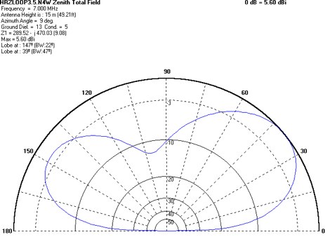
 Antenna model for a diamond loop wire antenna for the 40 meter band
 -
 A 5 element yagi beam antenna for ten meters band with full dimentsions, eznec file and coax match informations for 50 ohms feed line
 -
 An homebrew project for a 4 elements yagi monoband antenna for the 10 meters by 9M2MSO
 -
 A presentation of a HF multi-band sloper antenna. This antenna project is for low band operations, and antenna presented in this article works on 40 80 and 160 meters band. Article is in Polish.
 -
 A multiband coax trapped dipole for 10-80 meters bands by DF1PU
 -
 An high gain long yagi antenna, seven elements, for six meters band
 -

-
 Delta loop antennas for 40 meters plans and comparison of some models
 -
 A 2 element 40 meters band parasitic delta loop antenna project with pictures and details
 -
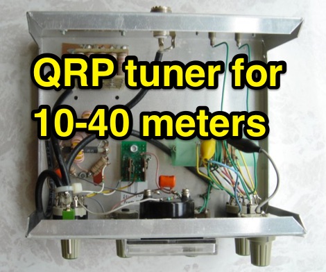
 Designing and constructing portable wire antennas for HF operations, this resource explores several configurations including the _foldback dipole_ for space-constrained setups and an inductively shortened dual-band dipole for 20m and 40m. It details the calculation of inductance for shortened elements, providing a Visual Basic 6.0 program screenshot that illustrates determining coil parameters like turns and length for a **25.5 uH** inductor. The document emphasizes practical considerations such as adjusting wire lengths for optimal SWR, noting that a dual-band dipole achieved SWR below 2:1 on both 20m and 40m, with careful adjustment bringing it under 1.5:1. Further, the resource describes a half-wave antenna matched with a coaxial stub, a method often referred to as the _Fuchskreis_ in German amateur radio circles, to transform the high feedpoint impedance to 50 Ohms. This monoband solution, for a 20m application, uses a stub length of **2.98m** (0.216 lambda multiplied by coax velocity factor) and a shorted stub of approximately 48cm. The coaxial stub design is highlighted for its resilience to ground proximity, allowing it to be rolled up or laid on the ground with minimal SWR impact, making it highly suitable for portable QRP operations.
 -
 Antenna tuners are crucial for matching the impedance of antennas to the 50 ohm output impedance of transmitters. The _LDG Z-11 Pro_ is an automatic antenna tuner designed to handle up to 125 watts, making it suitable for a wide range of amateur radio applications. Its compact form factor allows it to pair well with transceivers like the _FT-857D_, providing a portable solution for operators who frequently change locations or setups. The tuner covers the 80 through 6 meter bands, offering a broad impedance match capability. Although it struggles with some loads, it performs well with typical ham antennas, even managing to load an 80 meter dipole on 6 meters. One of the standout features of the _Z-11 Pro_ is its 8000 memory slots, which enable it to remember successful matches and quickly retune when revisiting frequencies. This memory function significantly reduces tuning time, often to less than half a second. The unit is well-constructed, with improved pushbuttons and a sturdy metal case that offers good shielding. However, users should be aware of potential RFI issues and the lack of a power switch, which requires disconnecting the power cord to turn off the unit completely. Overall, the _LDG Z-11 Pro_ is a user-friendly and cost-effective tuner, offering advanced features that enhance its utility in various amateur radio setups.
 -
 The page discusses the concept of a 2-element Parasitic Ground Plane antenna for the 40-meter band. It includes a conversation between amateur radio operators discussing modeling results and design considerations for the antenna. The author shares insights on radial configurations and the impact on antenna efficiency and pattern.
 -
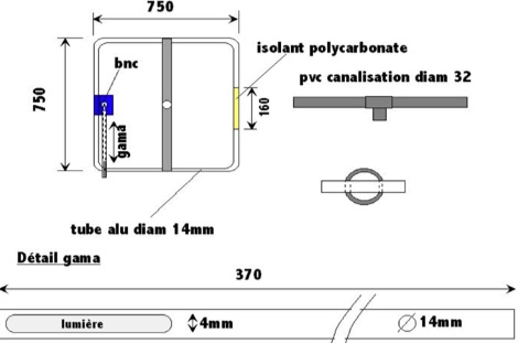
 Schematic diagram and description of a magnetic loop antenna that works from 10 to 20 meters band, made from junk
 -
 Building a Windom HF Antenna. A PDF file presentation about homebrewing a windom antenna for the HF bands with formulas for 40 and 80 meters bands and step by step guide on making a 4:1 balun to feed the antenna.
 -
 A multi band portable link dipole antenna for 20 30 and 40 meters band
 -
 Testing performances of indoor antenna. A comparison of a magnetic loop antenna vs a classic wire dipole done using wsprlite on 30 meters band.
 -
 Digital radio mondiale DRM products, measuring tools, Magnetic field probes, RF power meters, Broadband loop antennas, DRM devices and services
 -
 An home made HF mobile multiband antenna inspired by the KM4IE HF 20 dollars antenna or the Texas Bugcatcher can work 75 to 15 meters band with an acceptable SWR.
 -