Search results
Query: 11 meters
Links: 55 | Categories: 0
-
 Demonstrates the construction of a **multi-band HF mobile antenna** utilizing a modified CB whip antenna base. The resource details the process of stripping a commercial CB whip, winding a new helical coil with 0.7mm insulated copper wire, and identifying tapping points for various HF bands. It emphasizes the importance of a rugged, slim design for mobile operation, discussing mechanical length, power handling (up to 200 watts), and coil diameter considerations. The article includes a graphic illustrating the antenna's operational principle, where sections of the helical coil are shorted from bottom to top to maintain efficiency and high Q. The resource presents a practical approach to achieving **band switching** without an external tuner, by manually adjusting tapping points on the coil. It provides a table with reference lengths in centimeters from the feedpoint for 7 MHz (40m) through 28.7 MHz (10m), including WARC bands. The author details mounting techniques, suggesting a Diamond bracket for secure attachment to a vehicle trunk, and stresses the critical role of proper grounding for optimal performance. The design allows for operation on 75m and 80m bands by adding a 110mm steel whip.
 -
 Details the construction of a J-vertical antenna specifically for the 10-meter band, offering a practical alternative to a _Slim Jim_ design for 28 MHz. The resource outlines the use of aluminum tubing for the half-wave vertical section and coaxial cable for the quarter-wave matching section, providing specific calculations for element lengths based on frequency and coaxial cable velocity factor. It contrasts the performance of the J-vertical with center-fed dipoles and end-fed verticals, noting superior results in previous comparisons. The article further presents a more recent iteration of the J-vertical, constructed using a fiberglass pole and insulated wire, with updated dimensions for 28.8 MHz. It includes practical advice on weatherproofing connections and securing the antenna for durability against adverse conditions, referencing the survival of an original _J Vertical_ during 110 MPH winds in 1987. The SWR performance is reported as 1.1:1 at 28.6 MHz, maintaining below 1.5:1 across 28.3 to 29 MHz.
 -
 11 Meter CB, 10 Meter Amateur Ham, FRS, GMRS Radios, Test Meters, Scanners, Antennas, Microphones, Power Supplies, Inverters, Accessories and Technical Reference Information.
 -
 10 meter modification for the Ameritron AL-811 and AL-811H amplifier. This mod apply to other Ameritron AL Series RF amplifiers and allow extension to 10 and 12 meters band.
 -
 Normal mode helix antennas for HF mobile. Photos andn plan for a 20 meters mobile helix antenna by N2MH
 -
 Experimental omni-directional antennas for 6-meters band
 -
 Moxon antenna for 50 MHz, The Moxon rectangle is a quite broad-band antenna, but it is not quite broad enough to cover the entire band.
 -
 10 meters band aluminum 2-Element Moxon rectangle
 -
 Selecting an appropriate antenna system for shortwave broadcasting involves evaluating various types based on performance, cost, and operational parameters. This resource details the critical specifications for broadcast antennas, including average and peak power ratings, directivity, takeoff angle (TOA), horizontal beamwidth, and gain, emphasizing that a 100-kW transmitter requires an antenna rated for 150 kW average and 400 kW peak. It clarifies that low TOA signals travel thousands of kilometers, while high TOA is for local coverage, and nearly all modern shortwave broadcast antennas are horizontally polarized. The article explores specific antenna types, such as Log-Periodic Antennas (LPAs), which offer wide frequency ranges (e.g., 2-30 MHz) and directional patterns with 11 dBi gain, costing from $20K to over $100K for multi-curtain versions. Dipole arrays, also known as curtain antennas, are prevalent in international broadcasting, featuring steerable beams (±15° and ±30°) and mode-switching capabilities to alter TOA, with high/low pairs costing over $1 million. Fan dipoles are noted for omnidirectional patterns, smaller size, and lower cost for low-power applications, while rhombics, though simple, require resistive termination and incur several dB of I2R losses. Balun considerations are crucial, as most communications baluns are not rated for the higher average and peak powers of AM broadcast transmitters. Modern shortwave antennas utilize durable materials like Alumoweld wire rope for radiators and support elements, avoiding copper, fiberglass, or materials prone to stretching or deterioration. Feeder systems for high-power stations often require tapered-line baluns to convert 50-ohm unbalanced power to 300-ohm balanced for connection to the antenna.
 -
 The total length of this antenna is 41m, height is about 11m, and diameter of element is 2mm. JA7KPI modified this antenna originally used as Inverted-V type of 80m band Dipole. Works on 40 - 80 meters band with acceptable swr.
 -
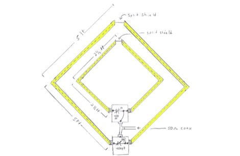
 This document by W4HM explains the construction and usage of a 160 meter balanced coaxial receiving loop antenna, which can be easily adapted for the 40 and 80 meters bands. The content provides detailed instructions on building the antenna, its advantages, and how to optimize its performance for amateur radio operations. It is a valuable resource for radio amateurs looking to improve their receiving capabilities and enhance their overall radio communication experience.
 -
 Interesting article on mobile antennas by Cebik. . The article offers advice for setting up and operating mobile antennas for ham radio use. It emphasizes the lossy nature of mobile-in-motion antennas but encourages users to rise to the challenge. Steps include safeguarding car electronics, choosing proper cabling, and carefully selecting and mounting antennas. It highlights potential issues like roof mounting, trunk lip grounding, and side-mounting for trucks. For stationary operation, options like dipoles or beams are explored, with safety tips for masts and guying systems. Lastly, it stresses safety, suggesting stopping the vehicle to operate whenever possible
 -
 Notes on building a basic wire vertical or horizontal antenna for 160 meters band by L. B. Cebik, W4RNL
 -
 AM/FM/CW QRP RF Power Amplifier for the HF 10 or 11 meterband (28MHz/27MHz)
 -
 The BV6 50 MHz Yagis resource details the construction of two distinct Yagi antenna designs for the 6-meter band, specifically a 1-wavelength (1wl) model and a 2.1-wavelength (2.1wl) model. The 1wl Yagi, with a boom length of 5.850m, achieves a gain of **9.4 dBd**, while the 2.1wl Yagi, spanning 12.90m, boasts a gain of **11.9 dBd**. These designs adhere to a proven methodology for optimizing current slope and maintaining constant phase delay across parasitic elements, ensuring high gain per boom length and an _excellent pattern_. Both designs target a 50-ohm input impedance, facilitating straightforward feeding with a robust folded dipole. Final verification using NEC-II software confirmed the antennas' exceptional stacking capabilities, yielding stacking gains exceeding **5.8 dB** for a 2x2 array with minimal mutual detuning. The resource provides common mechanical data, including boom and element diameters, and specifies element lengths corrected for boom diameter. While the original _DUBUS Technik V_ publication contained incorrect element lengths, this resource provides the accurate dimensions for proper construction, emphasizing the use of readily available materials for cost-effective amateur radio deployment.
 -
 A double dipole for the 20 and 15 meters band in french
 -
-
 Designing quagi and yagi antennas on 2 Meters, some preliminary notes by Cebik, W4RNL
 -
 A High Efficiency Extended Length Mobile Antenna The antenna itself is 3.42 meters or 11 feet 2 inches long from the top of the mounting spring to the tip.
 -
 A direct drive ring radiator antenna for the 40 meters band by W6WYQ QST article.
 -
 N0KHQ Moxon rectangle for 17 meters, constructed from RG-58 coaxial cable
 -
 Doublet multiband antenna for 80 to 10 meters band by
 -
 This resource details the computer-optimized design of the _ZS6BKW_ multiband dipole, an evolution of the classic _G5RV_ antenna. It begins by referencing the original 1958 RSGB Bulletin article by Louis Varney G5RV, explaining the operational principles of the G5RV's flat-top and open-wire feedline on 20m and 40m, noting its impedance transformation characteristics for valve amplifiers of that era. The article then transitions to the rationale for optimizing the design for contemporary solid-state transceivers requiring a 50 Ohm match. The core of the project involves using computer modeling to determine optimal lengths for the flat-top and matching section, aiming for a VSWR of less than 2:1 on multiple HF bands. It discusses the process of calculating feedpoint impedance based on antenna length and frequency, referencing professional literature from Professor R.W.P. King at Harvard University. The analysis also considers the characteristic impedance (Z(O)) of the open-wire line, identifying a broad peak of adequate values between 275 and 400 Ohms. Specific design parameters for the improved ZS6BKW are presented, including a shorter flat-top and a longer matching section compared to the original G5RV, with a velocity factor of 0.85 for the 300 Ohm tape. The article confirms acceptable matches on 7, 14, 18, 24, and 28 MHz bands when erected horizontally at 13m, and also discusses performance in an inverted-V configuration, noting frequency shifts. The author, Brian Austin ZS6BKW, emphasizes the antenna's suitability for modern 50 Ohm coaxial cable without a balun.
 -
 An home made trapped dipole antenna for 40 and 60 meters band by 2E0HTS
 -
 Alfa Tango DX is a premier resource for operators on the 11 meters band, providing a searchable database that includes news, cluster information, and discussion boards. This platform serves as a hub for DXers and contesters, offering valuable insights into activations, dx-peditions, contests, and meetings worldwide. The site features a variety of resources, including event calendars, award programs, and tools for logging contacts. Members can access exclusive content and participate in contests like the AT Women's Day Contest and the Eleven World Wide Contest. With a focus on community engagement, Alfa Tango DX fosters connections among operators and promotes the spirit of amateur radio. Whether you are a seasoned DXer or a newcomer to the 11m band, Alfa Tango DX provides essential information and support for enhancing your amateur radio experience. From QSL services to event participation, this resource is designed to meet the needs of all operators interested in the 11 meters band.
 -
 A 10 meters band Slim Jim antenna project, made with a 450 Ohm slotted ribbon cable and secured on a 8 m fishing pole, by Steve G0KYA
 -
 The ZS6BKW antenna, a popular multiband wire antenna, offers improved band matching compared to the traditional G5RV. This construction guide details the process, beginning with specific dimensions: 13.11 meters (43 feet) for the 450-ohm ladder line and initial dipole arm lengths of approximately 14.8 meters each. It emphasizes the critical role of an _antenna analyzer_ for accurate tuning, particularly for determining the velocity factor of the ladder line and achieving a 1:1 impedance match. The article outlines the materials required, including a 1:1 current balun, 450-ohm window line, wire for the dipole arms, and a 50-ohm non-inductive resistor for testing. It provides a step-by-step procedure for cutting the ladder line to its electrical half-wavelength, explaining how to calculate the velocity factor using measured and free-space frequencies. For instance, a measured 50-ohm impedance at 12.54 MHz with a calculated free-space half-wavelength frequency of 11.44 MHz yields a velocity factor of 0.91. Final adjustments involve hoisting the antenna to its operational height and fine-tuning the dipole arm lengths to achieve optimal SWR, specifically targeting 14.200 MHz. The _ZS6BKW_ design is noted for its performance on 80m, 40m, 20m, 10m, and 6m, though it is not optimized for 15m operation. The author, _VK4MDX_, shares practical tips for durable construction using stainless steel wire and cable clamps.
 -
 An end-fed halfwave antenna for 20 meters band with balun pictures and description by PD7MAA
 -
 Presents the DBO274 Citizen Band mailbox, a digital communication hub accessible via HTTP and Telnet, specifically catering to **CB radio** enthusiasts in Germany. This resource outlines its functionality for Packet and other digital emissions on the 11-meter band, a segment often overlooked by traditional amateur radio operators but vital for CB users seeking advanced communication methods. The author, DH8YMB, provides insights into its operation, reflecting practical experience with digital modes in the CB spectrum. The DBO274 serves as a bridge, enabling users to exchange messages and data packets, extending the reach and utility of standard CB transceivers. It represents a localized digital infrastructure, demonstrating how the 27 MHz band can support more than just voice contacts, incorporating elements of early internet-like communication within the CB community. This setup highlights the enduring innovation within the CB realm, adapting technologies like Packet Radio for a different user base. It underscores the versatility of radio communication, even on less conventional bands, for those interested in digital data exchange beyond the typical amateur allocations.
 -
 DX_Central, a compact desktop application, provides amateur radio operators with critical propagation data by aggregating solar statistics and imagery from various authoritative sources. This includes real-time information from agencies like NOAA and NIST, offering insights into current space weather conditions that directly impact HF propagation. The software is designed for both Linux and Windows operating systems, making it accessible to a broad range of hams. It presents a concise overview of solar activity, which is essential for planning DX operations and understanding band openings and closures across the HF spectrum. Operators can utilize the displayed solar flux index, K-index, and other relevant parameters to make informed decisions regarding their operating times and target bands, optimizing their chances for successful long-distance contacts.
 -
 A Loop Fed Array Yagi antenna for 50 MHz featuring 11 dBi gain and 23 f/b ratio. In this excellent page the author even includes a detailed drawing in DWG format, with element lenght and spacing measures, in a separa file a full list of material list needed to build this yagi antenna including source and price, the EZnec file for this antenna plan, and a lot of pictures of this LFA Yagi for 50 Mhz. A ten page PDF file containing all infos, is also available to download.
 -
 This is the schematic of asolid-state 7 MHz QRP CW transmitter by VU2NAN
 -
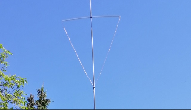
 A three band short Vee antenna is feasible with two legs per side on a dipole. 10-15-20 meters by W8HDU
 -
 A Co-ax Trap Dipole For 40, 30 and 20 Meters or at last that was the intention
 -
 Antenna tuners are crucial for matching the impedance of antennas to the 50 ohm output impedance of transmitters. The _LDG Z-11 Pro_ is an automatic antenna tuner designed to handle up to 125 watts, making it suitable for a wide range of amateur radio applications. Its compact form factor allows it to pair well with transceivers like the _FT-857D_, providing a portable solution for operators who frequently change locations or setups. The tuner covers the 80 through 6 meter bands, offering a broad impedance match capability. Although it struggles with some loads, it performs well with typical ham antennas, even managing to load an 80 meter dipole on 6 meters. One of the standout features of the _Z-11 Pro_ is its 8000 memory slots, which enable it to remember successful matches and quickly retune when revisiting frequencies. This memory function significantly reduces tuning time, often to less than half a second. The unit is well-constructed, with improved pushbuttons and a sturdy metal case that offers good shielding. However, users should be aware of potential RFI issues and the lack of a power switch, which requires disconnecting the power cord to turn off the unit completely. Overall, the _LDG Z-11 Pro_ is a user-friendly and cost-effective tuner, offering advanced features that enhance its utility in various amateur radio setups.
 -
 An homebrew project of a full wave delta loop antenna for the 40 meters band with dimensione, picture and assembling instructions in Indonesian
 -
 Demonstrating the construction of a short dipole antenna tailored for the 60 meter band, this resource provides detailed instructions for radio enthusiasts with limited space. The design incorporates inductive loading using two inductors (L1/L2) made from PVC tubes, allowing for effective operation on 5 MHz. The antenna consists of 12 meters of wire, divided into four sections, with specific dimensions and materials outlined for optimal performance. Results from users indicate that this antenna can significantly enhance DXing capabilities on the 60 meter band. Feedback from operators suggests that while the design is effective, adjustments may be necessary based on individual setups, such as coil diameter and wire gauge. Many users report successful construction and operation, with some experimenting with variations to improve resonance. The practical application of this antenna design has led to successful contacts and improved signal quality, making it a popular choice among 60 meter band operators.
 -
 The **Solarcon A99** vertical antenna, a half-wave over a quarter-wave variable mutual inductance design, primarily serves the 11-meter CB band but also finds use on 10 and 12 meters for amateur radio operators. Its simple construction, consisting of three fiberglass sections and a 16 AWG radiating element, makes it an accessible option for new operators or those seeking an easy-to-install base station antenna without complex mounting requirements. Despite claims of 9.9 dBi gain being widely considered exaggerated, and a manufacturer rating of 2000 watts power handling often viewed with skepticism (with 300 watts suggested as a practical limit), the A99 maintains popularity due to its low cost and ease of deployment. It typically tunes to a 1.2-1.3 SWR out of the box, requiring minimal adjustment via its two tuning rings. Its high angle of radiation allows for effective local communication even when mounted at low heights, such as 8-10 feet off the ground. However, the A99 is known for significant RF bleed-over issues, particularly when operated with higher power or mounted close to residential electronics. While its internal design is often described as cheap, the antenna exhibits remarkable durability, frequently lasting a decade or more in various weather conditions. Its affordability and straightforward setup continue to make it a go-to choice for many radio enthusiasts.
 -
 A moxon antenna for the 50 MHz build with 19 feet of 14 AWG copper wire, and based on a set of PVC pipes. This is an easy to build project that will give you an efficient directional antenna on 6 meters band with low SWR on more than 1 MHz bandwidth.
 -
-
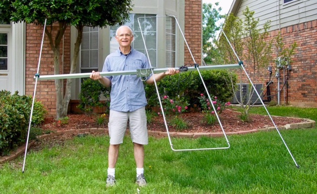
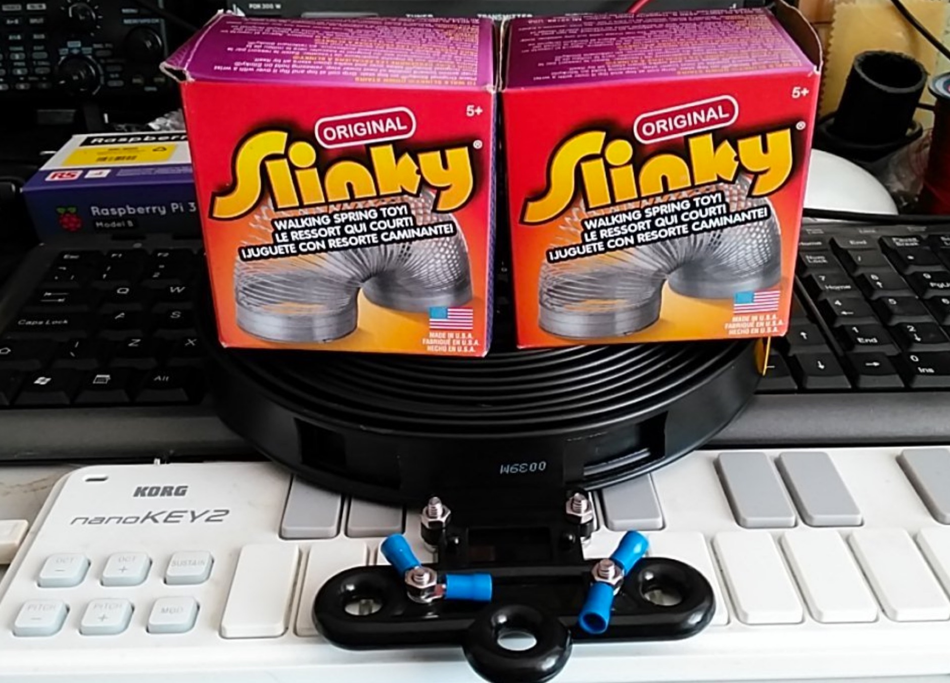 An home made doblet antenna made with two Slinkys that are aproximately five meters in length connected with a twin-feed connected to a balanced ATU
 -
 A dual band dipole antenna for 40 and 80 meters band. Total lenght of 26 meters, foreseen two coils at aprox 11 meters distance from center feed.
 -
 Presents a historical timeline of amateur radio satellites, beginning with the inaugural _OSCAR 1_ in 1961 and extending through ARISSat-1 in 2011. It outlines the evolution of these orbiting transponders, initially simple battery-operated beacons, into sophisticated platforms supporting educational initiatives, emergency communications, and technology demonstrations. The document highlights the significant contributions of various AMSAT organizations and other entities in developing and deploying these spacecraft. Each entry provides specific launch details, including the date, launch vehicle, and initial orbital parameters such as apogee, perigee, and inclination. For instance, AMSAT-OSCAR 7 (AO-7) launched in 1974 into a 1459.00 x 1440.00 Km orbit, while AMSAT-OSCAR 40 (AO-40) achieved a highly elliptical 58665.00 x 1157.00 Km orbit. The resource also notes the allocated amateur satellite service frequencies, including 29 MHz (10m), 145 MHz (2m), 435 MHz (70cm), 1270 MHz (24cm), and 2400 MHz (13cm). The compilation serves as a concise reference for understanding the progression of amateur satellite technology and operations over five decades, showcasing the collaborative efforts of the global amateur radio community in space communication endeavors. It details the physical characteristics and project affiliations for many of the **20** satellites listed, providing a foundational historical context.
 -
 A homebrew radio transmitter project, based and inspired by the original 30 Watts input on 80 50 and 15 meters band transmitter by W11CP
 -
 The TX & RX DX Group is a group that was created inside the TX & RX Forum. Several colleagues reported in TX & RX Forum were participating in a thread about the DX on 11 meters and so it happened
 -
 A homemade delta loop antenna for six meters band in German
 -
 Getting Started on the Magic Band is a very exaustive article about operating the six meters band. It covers several aspects of operations, techniques, tips and guidelines on getting started on the six meters band.
 -
 WebSDR Pardinho SP Brazil providing access to HF bands 160 80 40 20 15 11 meters bands.
 -
 With this antenna the coverage is 80,40,20,15 and 10 meter band without any antenna tuner and the average SWR is below 1.2 on phone bands. The total antenna lenght is about 23 meters , with one 20.4 meters long segment from the 1:49 transformer to the 110uh coil and about 2.2 meters long segment from the coil to the insulator.
 -
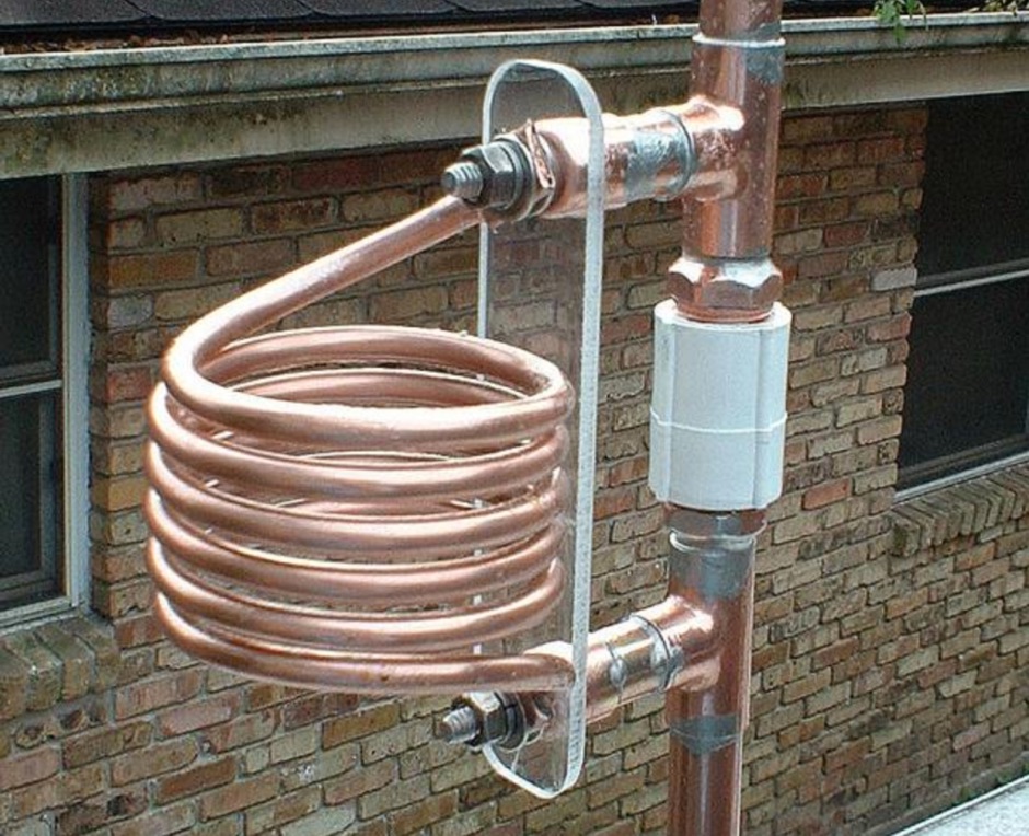
 Jeri Ellsworthhas started a video series devoted to building a magnetic loop antenna for the 160- and 80-meter bands. The first video, included after the break, is an overview of the rationale behind a magnetic loop