Search results
Query: HF 6m
Links: 99 | Categories: 1
-

-
 A 9 dB gain 70cm collinear antenna construction is detailed, utilizing eight half-wavelength sections of _RG58/U_ coaxial cable. The design incorporates specific calculations for velocity factor (0.66 for RG58/U) to determine precise element lengths, such as 223mm for a half-wavelength at 444 MHz. A quarter-wave radiating element of #16 solid wire, 169mm long, is added to the top, and a 160mm aluminum tube acts as a quarter-wave counterpoise at the feed point. RF choke baluns, constructed from three _FT50-43_ toroids, are positioned a half-wavelength from the feed point to mitigate common mode current. Assembly involves soldering the coax sections in series, followed by SWR testing during construction and final mounting within a ¾-inch PVC pipe. The article suggests using four half-wave elements for a shorter antenna, noting a potential slight increase in SWR, which can be mitigated with quarter-wave ground radials. The design principles and formulas are scalable for other VHF/UHF bands like 6m, 2m, or 1¼m, providing a versatile homebrew solution for enhanced gain.
 -
 Calculate Double bazooka for Win3/Win95 by W4BEJ
 -
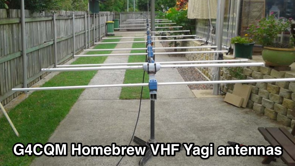 Homebrew VHF Yagi 50MHz 144MHz 432MHz 1296MHz 2320MHz 6M 2M 70CM 23CM 13CM Yagis
 -
-
 A self-supporting vertical antenna design for stationary-mobile HF-VHF operation is presented, emphasizing ease of construction with common materials like a fiberglass fishing rod and PVC pipe. The design focuses on creating a set of no-tuner monoband radiators for bands such as **2m**, **6m**, 10m, and 12m, with an overall radiator support length of 3.3m. The construction process details the assembly of the antenna base using a magnetic mount, PL-259 connector, and PVC pipe sections, which then supports the telescopic fishing rod. Radiator extensions are cut to achieve quarter-wave resonance on specific bands, with detailed instructions for 6m (50-51 MHz), 10m (28.5 MHz), and 12m (24.9 MHz). For lower HF bands like 15m, 17m, and 20m, the design incorporates base-loading coils, with specific turn counts provided (e.g., 21 turns for 20m). The project also suggests using an _antenna analyzer_ for precise tuning of extensions and coils, moving beyond theoretical values to achieve optimal performance. The author, _IK1ZYW_, notes that for 80m and 160m, the antenna becomes less efficient as a vertical, suggesting alternative configurations like an inverted-V dipole or asymmetrical inverted-L.
 -
-
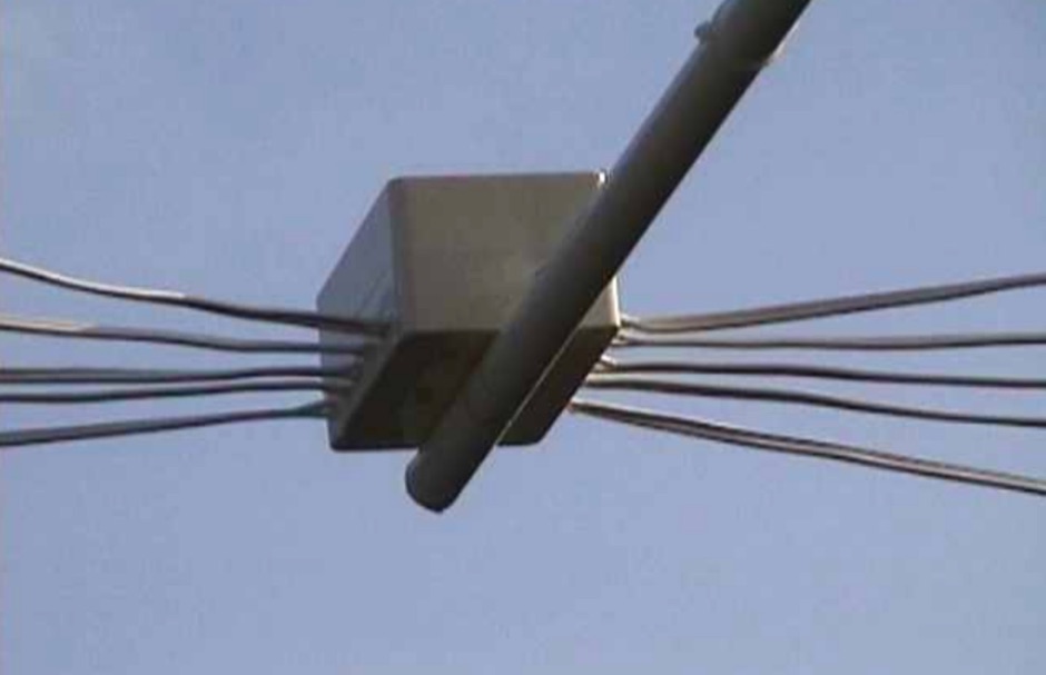 The cobweb antenna it is basically a 5 band antenna comprising of 5 full half wave dipoles for each band - between 10 meters and 20 meters, the antenna is also resonant on 6M and can be modeled even for VHF frequencies.
 -
 Demonstrates the construction and performance of an updated ZS6BKW multiband dipole, a variant of the _G5RV_ antenna, specifically designed for HF operation. The article details a real-world installation using 13.5m copper wire elements and 12.2m of 450 Ohm ladder line, configured as a sloping inverted-V with the apex at 10m and ends at 4m above ground. It covers the critical aspect of impedance matching, incorporating an 8-turn choke balun at the feedline transition to RG-58U coax to mitigate RF common mode current. Measurements confirm favorable SWR readings below **1.3:1** on 7.1 MHz, 14.11 MHz, 18.06 MHz, and 24.8 MHz, indicating effective resonance across 40m, 20m, 17m, and 12m bands. The installation also shows usable SWR dips on 3.55 MHz (5:1), 29.02 MHz (2:1), and 50.84 MHz (3:1), extending its utility to 80m, 10m, and 6m with an antenna tuning unit. Initial on-air results report clear reception of stations over **5000km** away, validating its DX potential.
 -
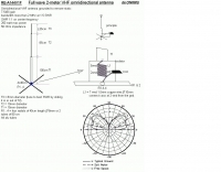 A full wave 2-meter VHF omnidirectional antenna by ON6MU
 -
 Suitable antenna for owners of an IC706 or FT817, 857 and other HF portable transceivers. You can an be QRV in a few minutes on all ham-bands from 80m to 6m and even on 2m by PA0FBK
 -
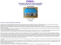 This project uses a widely available IRF510 MOSFET, work on HF 80, 40, 30, 20 and 17 meter bands
 -
-
 The AZIMUTH program plots a world map in either azimuth (beam heading) or Mercator projections. If you specify your home location in latitude and longitude, the azimuth projection is centred on your location. The Azimuth map program can display Maidenhead grids - this is useful for 6m, 2m, and UHF DX communication display. Various features of the map are: Azimuth or Mercator projections , Maidenhead grid display, Simple map zooming, Print maps with adequate resolution up to one meter sized map
 -
 The ZS6BKW multiband HF antenna, a design by ZS6BKW (G0GSF), functions effectively on multiple HF bands without requiring an Antenna Tuning Unit (ATU) for 40, 20, 17, 12, 10, and 6 meters. This antenna, approximately **27.51 meters** (90 feet) long with a 12.2-meter (40-foot) open-wire feeder, is a direct descendant of the _G5RV_ but offers superior multi-band resonance. It can be deployed as a horizontal dipole or an inverted-vee, with the latter requiring only a single support and maintaining an apex angle of at least 90 degrees to prevent signal cancellation. Performance data, recorded with an MFJ Antenna Analyser, indicates SWR values of 1:1 on 7.00 MHz (40m) and 14.06 MHz (20m), with SWR below 1.3:1 on 17m, 10m, and 6m. While primarily designed for these bands, the antenna can be adapted for 80m, 30m, and 15m with an ATU, preferably at the balanced feeder's base. The use of 450-ohm twin-lead for the feeder is recommended over 300-ohm for improved strength and reduced losses, especially in adverse weather conditions. This design, originally published in _RadCom_ in 1993 and featured in Pat Hawker’s "Antenna Topics," provides a compact and efficient solution for HF operation, particularly for those with limited space or resources.
 -
 Stacking and phasing HF and 6m arrays antenna switches and contesting devices. Custom low band antenna arrays, bandpass filters,commercial/Mil STd filters,microwave components, commercial broadcast filters.
 -
-
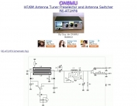 HF/6M antenna tuner preselector and antenna switcher project by ON6MU
 -
 AM/FM/CW QRP RF Power Amplifier for the HF 10 or 11 meterband (28MHz/27MHz)
 -
-
-
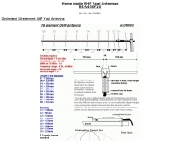 ON6MU Optimized 10 and 6 and 4 element UHF Yagi Antenna
 -
 146MHz 5/8 ground plane tower mounted antenna. The antenna was largely based information and analysis provided by the RSGB's. VHF UHF Manual, fourth edition by G.R.Jessop, G6JP
 -
 A Versatile Innovative Portable Multi-band Tunable Antenna can work HF VHF and UHF ideal as portable or balcony antenna
 -
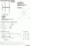
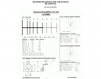 ON6MU optimized 6/9 element vhf yagui antenna with antenna schematic plan and pictures of homebrewed samples.
 -
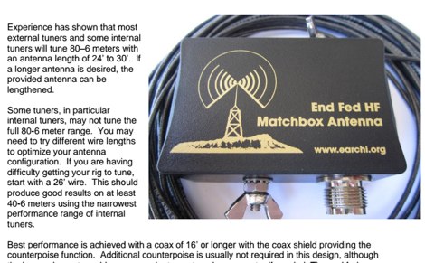 6m to 40m EndFed Half Wave Antenna project produces an inexpensive, multiband, end fed HF antenna matchbox that is quick and easy to setup and use.
 -
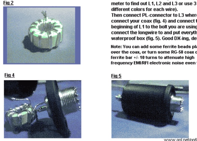 RF Choke to prevent hf currents on the feedline. This Magnetic Longwire Balun (MLB) makes it possible to efficiently use a coaxial lead-in cable with all forms of longwires, T-forms or other types of wire antennas, without the need for an antenna tuner.
 -
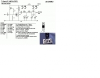 An RF power amplifier, providing 7 Watts output in HF bands, schematic by ON6MU
 -
 RF Choke to prevent hf currents on the feedline or...1:1 Choke Balun, sometimes called the "UGLY BALUN"
 -
 A portable dualband dipole robust and compact antenna usable for horizontal and vertical polarisation by ON6MU
 -
 Wideband VHF/UHF/SHF monolithic PreAmp based on MARx-series by ON6MU
 -
 The Chameleon V1 HF Multiband Antenna is a mobile antenna that can also be used as portable. Lightweight mil whip antenna system with 10 BANDS capability 6m, 10m, 12m, 15m, 17m, 20m, 30m, 40m, 60m & 80m.
 -
 This Magnetic Longwire Balun (MLB) makes it possible to efficiently use a coaxial lead-in cable with all forms of longwires, T-forms or other types of wire antennas, without the need for an antenna tuner.
 -
 The Discovery series of amplifiers are designed and built in the UK by Linear Amp UK Ltd, one of the world's leading amplifier manufacturers, specializing in high power RF tube amplifiers. The amplifiers use large GS31 or GS35 ceramic triode tubes. Band coverage 6m, 2m and 70 cms
 -
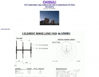 VHF Optimized Yagi Antenna for the 6-meter band (50 Mhz) by ON6MU
 -
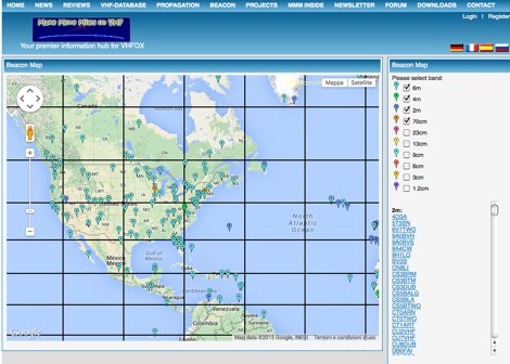 MMMonVHF maintains the data for 6m, 2m, 70cm and 23cm bands in collaboration to LA0BY. This site allow display of a beacon map and latest beacon spots.
 -
 Demonstrates the iterative design and construction of a **tapped HF/VHF mobile vertical antenna** by K0EMT, detailing four generations of development. The antenna supports operation on 80m, 40m, 30m, 20m, 17m, 15m, 12m, 10m, 6m, and 2m bands. Initial designs, like Generation 1, featured a 3/8" x 24TPI bolt in a PVC end cap with a 1" aluminum tubing mast, resulting in a 9'9" overall length and resonance around 6.9 MHz with the full coil. Subsequent generations refined the mast and coil forms, transitioning from aluminum to copper tubing (Generation 3, found too weak) and eventually fiberglass for the coil form (Generation 4, in progress). Coil tapping points were adjusted to achieve resonance without an external tuner in Generation 2. The project outlines material costs, totaling approximately $25, and mentions a successful 28 MHz QSO with EA3XA using an ICOM IC-706 mk II at 100 Watts. For 80m operation, an external wire with the maximum coil setting is used, or a 56" extender below the coil for stationary use.
 -
 A small portable antenna tuner for HF and VHF bands by ON6MU
 -
 This resource details the construction of a mobile screwdriver antenna, patterned after the original W6AAQ DK3 design from 1991. It covers the mechanical and electrical aspects of building a robust, multiband HF antenna for vehicular operation. Specific components discussed include the lower mast section, the coil wound on Schedule 40 PVC pipe, beryllium copper contact fingers, the motor drive assembly utilizing a Black & Decker screwdriver, and the capacity hat design with a brass hub and steel wires. The article provides insights into material selection, such as heavy copper tubing and silicone grease for assembly, and addresses practical considerations like coil length limitations for 80m operation due to lathe size. The construction results in an antenna capable of tuning from 6.5 MHz (40m) up to 6m, with slightly reduced range when the capacity hat is installed. The author describes the mounting base with soldered brass nuts for secure attachment and a U-channel bracket for vehicle mounting on a Dodge Ram 1500. The article includes close-up photographs illustrating the coil, contact fingers, drive mechanism with rubber tubing clutches, and the capacity hat assembly. It also mentions the use of Rustoleum hammer finish enamel for painting the copper pipe, indicating attention to durability and aesthetics.
 -
 Constructing a high-gain, compact antenna for 2 meters often involves balancing theoretical performance with practical build challenges. WB8AHT recounts his journey in building a 6-element _Super Duper Moxon_ antenna for 144 MHz, inspired by designs from M0PXS and GW3YDX. He initially encountered discrepancies in published dimensions for the _HAARP Antenna_ and the _Super Moxon_, leading to on-air SWR issues and suboptimal performance. His methodical approach involved cross-referencing, direct communication with Phil Simpson (M0PXS), and iterative adjustments to element lengths based on observed results and a _SARK-110 Antenna Analyzer_ scan. After modifying the reflector/driven element and third director dimensions, the antenna achieved a respectable 1.35:1 SWR at 144.200 MHz. Field testing with 50 watts yielded contacts up to 500 miles, suggesting performance close to the 15 dBi gain predicted by _4NEC2_ software, despite its compact 40-inch boom. The article includes specific construction notes, such as tubing sizes (1/2-inch and 3/8-inch aluminum) and feedpoint spacing (50mm). The author's experience highlights the importance of real-world validation for antenna designs, even those with strong theoretical backing. He provides a table of tubing lengths for 6m, 4m, and 2m versions, along with his final, optimized dimensions, offering a practical blueprint for fellow hams interested in replicating or further experimenting with this high-performance, small-footprint VHF antenna.
 -
 Demonstrates the construction of two distinct wideband RF preamplifiers, detailing their component requirements and performance characteristics. The first design leverages monolithic microwave integrated circuits (MMICs) such as the MAR-6, MAR-8, or PGA103, offering a broad frequency response from DC to 2 GHz with a gain of 22.5 dB at 100 MHz and a noise figure typically below 3 dB. This MMIC-based amplifier incorporates protection against power supply transients and features a 50 Ohm input/output impedance, operating from an 8-20 volt supply with low current drain. The second preamplifier design utilizes a BSX-20 transistor, providing amplification across the 14 MHz to 550 MHz range. This simpler, more economical build achieves an average gain of 12 dB at 145 MHz and a noise figure of approximately 1.1 dB. It operates from a 7-15 volt battery supply with a current draw of 6 mA. Both projects emphasize critical construction techniques, such as maintaining short RF connections, ensuring 50 Ohm impedance paths, and mounting the circuit within a shielded enclosure to optimize performance and minimize noise. The resource also discusses phantom power options for antenna-mounted preamplifiers and precautions for use with transceivers, including output protection diodes and static bleeders.
 -
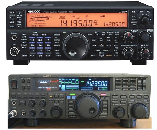 An interesting and very detailed report analysis of three populare HF+6m transceivers. Yaesu FT-950, ICOM IC-7410 and the Kenwood TS-590S by AB4OJ
 -
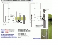
 The PDF document, titled "J-Poles," presents various J-pole antenna designs covering the 50 MHz to 450 MHz frequency range. It includes construction details for several specific bands, such as a 6-meter J-pole, a 2-meter J-pole, and a 70-centimeter J-pole. The content outlines the fundamental principles of J-pole operation, including the quarter-wave radiator and half-wave matching stub. Each design features specific dimensions for elements like the radiator length, stub length, and spacing, often expressed in inches. The document also discusses feeding arrangements and impedance matching considerations inherent to J-pole antennas. It provides practical guidance for homebrewing these antennas using common materials like copper pipe or wire elements. The resource offers insights into the advantages of J-poles, such as their omnidirectional pattern and ease of construction, making it a practical reference for radio amateurs interested in VHF/UHF antenna projects.
 -
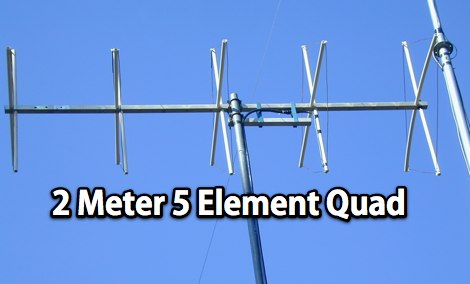 A five element quad antenna for 144 MHz DIY Project. This 2 Meter 5 Element Quad antenna was modeled using EZNEC, with a boom from a UHF TV antenna and CPVC pipe for spreaders. Constructed for 146MHz, it exhibits a gain of 10.7dB and an impedance of 75 ohms. Real-world results surpass the HT antenna, reaching over 20 repeaters up to 75 miles away. The design, costing around $10, employs simple tools for assembly.
 -
 The **70cm Moxon Beam** project outlines the construction and testing of a compact, directional antenna for the 432 MHz band. G3XBM recounts his early 1980s experience with a 4W FM321 transceiver and a Jaybeam 48-element TV antenna, which provided a baseline for his later UHF antenna experiments. This project focuses on a simpler, yet effective, design for local and regional contacts, emphasizing ease of construction and practical field results over complex theory. The article details the specific dimensions and materials used for the Moxon rectangle, including 6mm diameter aluminum tubing for the elements and a PVC boom. G3XBM notes that the antenna was built for portable use, making it lightweight and easily deployable for field operations. The feedpoint impedance was measured at 50 ohms, ensuring a direct match without the need for an external tuner, which simplifies setup. Performance tests included comparisons against a commercial 5-element Yagi, revealing that the Moxon provided comparable forward gain and an excellent front-to-back ratio, crucial for reducing local QRM. The author's observations confirm the Moxon's reputation as a robust performer for its size, suitable for both fixed and portable 70cm operations.
 -
 By Guy, de ON6MU, At VHF, both the 1/4-wavelength monopole and the 5/8-wavelength monopole antennas are widely used.
 -
 The resource details the construction of a 6-meter _Moxon_ antenna, presenting two distinct versions: one horizontally polarized for 50-51 MHz CW/SSB and another vertically polarized for 52-54 MHz FM. It specifies the use of 5/8 inch OD and 1/2 inch OD aluminum tubing, with 3/8 inch OD solid aluminum for corners, and provides a comprehensive material cutting schedule. The design aims for robust, portable construction, with all materials costing under $100. Detailed drawings and EZNEC models are referenced for precise dimensions and assembly, ensuring accurate element spacing and impedance matching. The EZNEC model for the H-POL version predicts a gain of **11 dBi** and a front-to-back ratio of **25 dB** at 50.5 MHz, while the V-POL version shows a gain of **6.7 dBi** and a front-to-back ratio of **36 dB** at 53 MHz. The article includes practical SWR measurement advice, noting the impact of coax length and loss on analyzer readings. Field tests during a tropical storm demonstrated the antenna's durability and performance, yielding numerous contacts across significant distances, including California, Colorado, and Texas, on SSB and PSK.
 -
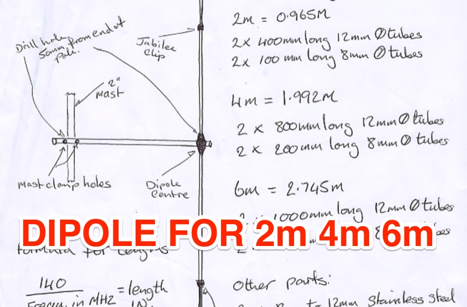 A dipole for 2m, 4m, 6m band an hamdwritten note for a homemade vhf antenna that can be tuned across the VHF band
 -
 This QRZ.com callbook entry by DL6GD details the construction and performance of a **40m/80m Morgain folded dipole antenna**. The resource includes a schematic diagram, construction photos, and tuning notes. The antenna, with a total length of **20.30m**, was mounted at a height varying from 4m to 6m above ground. Construction utilizes 0.75 sq mm transparent insulated copper wire, with Plexiglas spreaders (5mm thick, 70x10mm) spaced at 25mm intervals, secured with hot glue. A waterproof junction box houses the feedpoint and balun. Tuning involved adjusting wire bridges for resonance on each band. On 80m, an SWR of **1.1:1** was achieved at 3.657 MHz, with an SWR of 2.7:1 at 3.580 MHz and 2.5:1 at 3.755 MHz, yielding a bandwidth of 175 KHz. For 40m, an SWR of **1.1:1** was measured at 7.100 MHz, with 1.5:1 at 7.000 MHz and 1.3:1 at 7.200 MHz, providing a 200 KHz bandwidth. DL6GD notes that 80m tuning exhibits slight height sensitivity, while 40m tuning is less affected by height or 80m adjustments. Long-term observations from 2014 and 2022 document SWR degradation due to environmental factors like spiderwebs and ice accumulation, which can cause HF-conductive paths between elements. DXZone Focus: Callbook Entry | 40m/80m Morgain Dipole | SWR Measurements | 20.30m Length
 -
 The two linear amplifiers are ment for use with QRP SSB/CW/FM/AM transmitters on the amateur bands 15 and 17 meters can be powered from a 12 volt DC supply by ON6MU