Search results
Query: cable cal
Links: 151 | Categories: 2
-
 An Easy Dual-Band VHF/UHF vertical Antenna made with a TV twin lead and coax cable
 -
 This resource details the fundamental aspects of deploying longwire antennas, emphasizing ease of construction and installation for shortwave listening (SWL) and broadcast reception. It covers wire gauge selection, suggesting 14 to 24 AWG for general use, with heavier gauges (14-20 AWG) for permanent outdoor installations. Guidance is provided for various deployment scenarios, including indoor setups where the wire can be run around a room, temporary outdoor installations from balconies using light 18-24 AWG wire, and permanent outdoor configurations requiring higher placement and slack for tree movement. Feeding methods are discussed, recommending coaxial cable (50-75 ohms) to mitigate man-made interference, with instructions for connecting only the center conductor to the longwire. Safety precautions are highlighted, particularly avoiding contact with power lines and conductive materials, and managing static electricity buildup by unplugging the antenna after use and bleeding off charges before connection. The article also advises against using outdoor longwires during thunderstorms or snowstorms due to static and lightning risks. Optimal height considerations are presented, advocating for the highest safe placement, ideally a couple of feet above underlying structures, to maintain free air space. The text mentions a personal setup with one end at a roof peak (20 feet) and the other at a 17-foot mast, illustrating practical deployment without strict height requirements beyond safety and clearance.
 -
 Details the construction of a J-vertical antenna specifically for the 10-meter band, offering a practical alternative to a _Slim Jim_ design for 28 MHz. The resource outlines the use of aluminum tubing for the half-wave vertical section and coaxial cable for the quarter-wave matching section, providing specific calculations for element lengths based on frequency and coaxial cable velocity factor. It contrasts the performance of the J-vertical with center-fed dipoles and end-fed verticals, noting superior results in previous comparisons. The article further presents a more recent iteration of the J-vertical, constructed using a fiberglass pole and insulated wire, with updated dimensions for 28.8 MHz. It includes practical advice on weatherproofing connections and securing the antenna for durability against adverse conditions, referencing the survival of an original _J Vertical_ during 110 MPH winds in 1987. The SWR performance is reported as 1.1:1 at 28.6 MHz, maintaining below 1.5:1 across 28.3 to 29 MHz.
 -
 This resource presents the _FCC_ Online Table of Frequency Allocations, codified under 47 C.F.R. § 2.106. The document details frequency assignments across the electromagnetic spectrum, from 0 kHz to beyond 2170 MHz, specifying allocations for various radio services including amateur, maritime mobile, aeronautical radionavigation, and broadcasting. The table is structured with columns for International Table (ITU Radio Regulations Article 5, Section IV, 2019 Edition), United States Table (Federal and Non-Federal), and corresponding _FCC_ Rule Part(s). Specific frequency ranges, such as **135.7-137.8 kHz** and **472-479 kHz**, are identified with their primary and secondary allocations, including Amateur Radio (Part 97) and Maritime Mobile (Part 80). The methodology involves direct publication of regulatory data, reflecting amendments adopted by the _FCC_ that may not yet be codified in the Code of Federal Regulations. Each entry provides the allocated service (e.g., METEOROLOGICAL AIDS, RADIONAVIGATION), relevant footnotes (e.g., 5.53, US18), and the applicable _FCC_ Rule Part. For example, the 1800-2000 kHz range is allocated to AMATEUR radio under Part 97, alongside MOBILE services. Contact information for the Office of Engineering and Technology Policy and Rules Division is provided for inquiries regarding the data. DXZone Focus: Regulatory Database | FCC Publication | Frequency Allocation | Rule Part Reference
 -
 This is a vertical multiband antenna made up of several aerial elements lambda/4 length, feeded with just a coaxial cable in French.
 -
 Determining the actual need for an antenna tuner often hinges on the specific antenna and feed line configuration in use. While many hams believe a tuner is always essential, its primary role is to present a 50-ohm impedance to the transceiver, not to "tune" the antenna itself. For instance, a resonant dipole fed with _coaxial cable_ at its design frequency typically requires no tuner, as the feed line impedance closely matches the radio's output. However, operating a non-resonant antenna, or using a resonant antenna on multiple bands, frequently necessitates a tuner to manage high Standing Wave Ratio (SWR) on the feed line. The article clarifies that a tuner placed at the transceiver only matches the radio to the feed line, not the antenna to the feed line. For maximum efficiency with a non-resonant antenna, an _automatic antenna tuner_ (ATU) or a remote tuner placed at the antenna feed point is often more effective, minimizing losses in the feed line. The discussion also touches on the practical implications of SWR, noting that modern transceivers often fold back power at high SWR, making a tuner a practical necessity to achieve full output power, even if the antenna itself is not perfectly matched.
 -
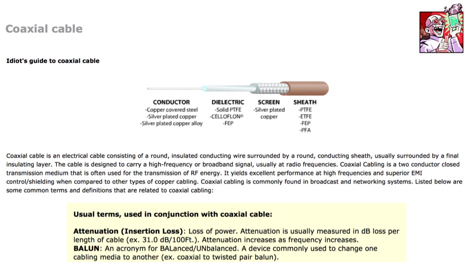 A very beginner's guide to coax cables. Characteristics, detailed comparison of typical coaxial cables, commonly used connectors, and a few words about SWR.
 -
 An efficient program to calculate dimensions of coax dipoles, or bazooka antennas considering velocity length of different coax cables. Express dimensions in feet/inch and meters/cm. Freeware by VE3SQB
 -
 This article describes how to make a quadrifilar helix (QFH) antenna easily, from inexpensive materials: uPVC plumbing pipe and RG-58U co-axial cable. A low-cost, easy-to-build Quadrifilar Helix (QFH) antenna for weather satellite reception using uPVC plumbing pipe and RG-58U coaxial cable. Unlike traditional designs requiring copper pipe and plumbing skills, this approach enables construction with basic tools and minimal technical expertise. The antenna's shorter, wider proportions favor higher elevation angles, reducing interference from horizon-level pager transmitters. Electrical connections are simplified at the antenna's apex, with the coaxial cable forming the radiating elements. Testing demonstrated consistent signal strength throughout satellite passes, proving effective weather satellite reception is achievable without precision engineering to sub-millimeter tolerances.
 -
 The Flower Pot Antenna project details a portable dual-band antenna primarily operating on 10 meters, with secondary resonance near the 30-meter band. Construction involves winding RG58 coaxial cable uniformly around a large plastic flower pot, approximately 70cm high with a 60cm top diameter. The design eliminates the need for radials, contributing to its compact and lightweight nature. Key construction steps include soldering the inner conductor to the shield at one end of the wound cable and connecting the wound cable's shield to the rig cable's inner conductor at the base. An LC network, comprising a variable capacitor (0-200pF) and an inductor (10 coils, 5cm diameter, 2mm wire), is inserted between the wound cable's inner conductor and the rig cable's shield. Tuning is performed with an antenna analyzer, adjusting cable length and the variable capacitor for optimal impedance on 10 meters. The antenna performs effectively when installed horizontally.
 -
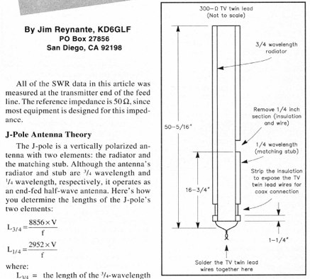
 This drawing shows a simple 10 meter wire J-pole antenna designed for 28.4 MHz. It is a vertical, end-fed Zepp-style antenna made from common materials and intended for easy home construction. The main radiating element is a straight length of stranded copper wire, either 14 or 18 gauge, cut to about 16.5 feet. At the top, the wire is supported by an insulator, allowing the antenna to be hoisted vertically. The matching section is made from 450-ohm ladder line, approximately 7 feet 9.5 inches long, and shorted at the bottom. This matching stub transforms the impedance so the antenna can be fed with coaxial cable. The feed point is tapped about 6 inches above the bottom of the stub, with the shield and center conductor connected at the proper points. A choke balun is formed with five turns of RG-58 coax in a 4-inch diameter loop to help reduce unwanted RF on the feed line. The drawing notes that this antenna has about 0 dBd gain, similar to a dipole, but offers an omnidirectional pattern and low-angle radiation when installed high. Its main advantage is practical performance, simple construction, and effective coverage for 10 meter operation.
 -
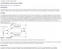
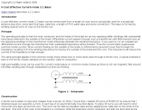 A cost effective current-mode 1:1 balun can be constructed from a length of coax and a rod typically used for a broadcast antenna loop-stick, some electrical tape, cable ties, a length of PVC water-pipe and some connectors.
 -
 This project details three variants of a vertical half-wave antenna design for the 4-meter (70MHz) amateur radio band. The antennas use end-feeding with a parallel-tuned circuit for impedance matching to 50-ohm coaxial cable. The first variant uses suspended flexible wire for portable use, the second employs a fiberglass rod with internal wire for permanent outdoor installation, and the third utilizes aluminum tent poles for quick mobile deployment. Despite the narrow bandwidth of the matching circuit, this suits the narrow 4m FM allocation well. The design offers an effective omnidirectional radiation pattern and can be constructed with readily available materials.
 -
 This article describes the construction of a Moxon rectangle antenna for the 70MHz (4-meter) amateur radio band. This compact two-element beam design features folded element ends, reducing its width to approximately 75% of a half-wavelength. The antenna was built using enamelled copper wire stretched over a lightweight fiberglass kite spar frame, with a direct coaxial cable feed connection. Initial testing showed a VSWR of around 1.3 with distinct nulls at 90 degrees when horizontally mounted. The author later tested vertical polarization and suggested that the antenna's compact size might allow for indoor loft installation.
 -
 This small window application will calculate Coax Cable loss from SWR and SWR from Cable Loss
 -
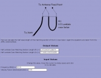 Online calculator for a 4 to 1 coax cable balun
 -
 One common challenge in antenna systems is mitigating common-mode current on the feedline, which can distort radiation patterns and introduce RF in the shack. This project details a 1:1 balun design that ingeniously avoids traditional ferrite beads, often a costly component, by substituting them with steel wool. The steel wool, when integrated into the balun's construction, effectively attenuates unwanted RF on the outer braid of the coaxial cable, ensuring that the antenna radiates efficiently and as intended. The construction involves winding coaxial cable through a PVC former, with the steel wool strategically placed to provide the necessary common-mode impedance. This method offers a practical and economical alternative for hams looking to build effective baluns without the expense or availability issues associated with ferrite cores. The design principles focus on creating a balanced feed to the antenna, crucial for optimal performance of dipoles and other balanced radiators. Experimentation with such designs can lead to improved field results, particularly for those operating with limited budgets or seeking innovative solutions for their antenna systems. The simplicity of using readily available materials like steel wool makes this a compelling build for many radio amateurs.
 -
 Described here is a simple omni-directional, vertically-polarized dipole for two meters. Made from coaxial cable, it can be rolled up and stored in a small container
 -
 Technical reference about Accessories, Amplifiers, Antennas, Cable and Connectors, Filters, Geography, Grounding, Gunk, Matching Networks, Projects, Propagation Info Radios, RFI/EMI, Rotors, Station Setup, Towers.
 -
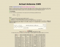 Easy for calculate formula which could be a wake-up call for you. The SWR value at the input of antenna cable is not a actual SWR of your favorite antenna.
 -
 Over 75 years of engineering expertise underpins Bird Electronic's offerings in RF power measurement, critical for maintaining peak performance in amateur radio stations and professional communication systems. The company specializes in a range of test equipment, including wattmeters, SWR meters, and antenna analyzers, essential for optimizing antenna systems and ensuring efficient power transfer. Their product line extends to various RF components such as filters, cables, and connectors, all designed to meet stringent technical specifications for reliability and accuracy across diverse frequency bands. Bird Electronic's instruments, like the _Bird 43_ Thruline Wattmeter, are widely recognized for their robust construction and precise measurement capabilities, providing hams with confidence in their station's operational parameters. These tools enable accurate assessment of forward and reflected power, SWR, and modulation characteristics, which are vital for troubleshooting and maximizing radiated power. The company's commitment to innovation ensures that its products remain relevant for modern RF challenges, from HF through microwave applications, supporting both traditional analog and advanced digital modes.
 -
 Details a practical QRP wattmeter construction, leveraging a simplified SWR meter design by JA6HIC. The project focuses on a forward-only power measurement circuit, providing a functional instrument for RF power levels from milliwatts up to 5 watts. It maintains a 50-ohm input and output impedance, suitable for typical QRP transceivers and antenna systems. The resource includes the schematic for the "VSW" (Very Simple Wattmeter) and outlines a six-step alignment procedure. This calibration process involves using a known RF source up to 5W, setting full-scale deflection, and marking power increments. It also addresses minimizing frequency effects on readings with a 100pF trimmer capacitor, noting that measurement error is highest at the lower end of the scale. Construction notes mention using a piece of RG-213 coaxial cable for the inductance and coupler, with the wattmeter assembled in early 2003. The author provides an example measurement showing 0.8W into a dummy load and 1W into a 3-element beam.
 -
 Demonstrates Belden's comprehensive portfolio of networking and cable solutions, emphasizing their application across diverse industrial and commercial sectors. The content details how Belden's infrastructure supports critical operations, enabling _network resilience_, edge computing, and data interoperability. It highlights tailored solutions for industries such as automotive manufacturing, chemical processing, and data centers, focusing on improving operational efficiency and ensuring uptime. The resource presents case studies and expert insights, demonstrating how Belden's offerings help organizations process data faster and maintain continuous connectivity, even amidst unexpected events. It underscores the company's role in providing robust infrastructure that merges IT and OT worlds, facilitating seamless data flow and informed decision-making across complex environments. The company's global presence is indicated by its **employees globally** and **Great Place to Work Certified countries** metrics.
 -
 A cost effective current-mode 1:4 balun can be constructed from two lengths of coax, two ferrite rods, some electrical tape, cable ties, a length of PVC water-pipe and some connectors. This form of 1:4 current-mode balun is named after G. Guanella.
 -
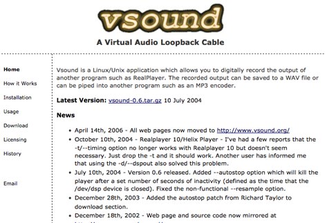 Vsound is a Linux software which allows you to digitally record the output of another program. The recorded output can be saved to a WAV file or can be transferred into another software. It's basically an audio transfer cable software.
 -
 The page describes the construction of a simple omnidirectional, vertically-polarised dipole antenna for two metres using coaxial cable. It can be used indoors or outdoors, with no extravagant gain claims. The project is low-cost and can be completed in about 20 minutes.
 -
 Constructing a compact, two-band magnetic loop antenna for HF operation, especially from constrained locations like a balcony, presents unique challenges. OK1FOU's design, inspired by DJ3RW's 50 MHz loop, addresses these by employing an unusual side-fed configuration and placing the symmetric, two-section variable tuning capacitor at the bottom of the loop, directly connected to the coax shield. The article provides specific material recommendations, including two 1-meter wooden pales and about 3 meters of thick loudspeaker cable, noting the high current (60A at 100W) in the loop. Construction steps detail forming two turns with a 5 cm gap, using a GDO to pre-tune the open loop to a frequency slightly above the desired highest band, and then integrating the tuning and coupling capacitors. For 10/14 MHz, an open loop resonance of 16-17 MHz is suggested. Practical experience with the 10 MHz band from a third-floor balcony in Prague (JO70GC) shows a 1:1 SWR across most of the band without an external ATU. While DX traffic was modest due to the urban environment, QSO examples with RA6WF, LA6GIA, G0NXA, and LZ1QK on 10 MHz are provided, demonstrating its operational capability.
 -
 Constructing a Lindenblad antenna for 137MHz NOAA satellite reception involves specific design considerations for optimal performance. The resource details the use of 4mm galvanised steel fencing wire, 300-ohm television ribbon cable, and wood/plastic components for the antenna structure. Key dimensions for a 137.58MHz-resonant antenna are provided, derived from the ARRL Satellite Handbook, specifying s, l, w, and d as 42, 926, 893, and 654mm respectively. The antenna is designed for Right Hand Circularly Polarised (RHCP) signals, requiring the four folded dipole elements to be tilted clockwise by 30 degrees. A significant aspect covered is impedance matching between the antenna's 75-ohm impedance and a typical 50-ohm receiver input. A twelfth-wave matching transformer, constructed from 117mm sections of 50-ohm RG-58 and 75-ohm RG-59 coax with a 0.66 velocity factor, is described. The article also addresses coaxial cable and connector selection, recommending 75-ohm Type-N connectors for RG-6 cable in professional setups and F56/F59 connectors for general use, while strongly advising against PL-259/SO-259 connectors for VHF. Strategies for mitigating Radio Frequency Interference (RFI) are discussed, including antenna placement to shield from local TV transmitters and the use of commercial or DIY band-pass filters, such as cavity resonators or helical notch filters, along with ferrite chokes on coaxial cables. Antenna orientation is explored, noting the Lindenblad's 'cone of silence' directly overhead and its maximized sensitivity towards the horizon. An experimental vertical tilt of 90 degrees is presented as a method to improve overhead reception and reduce interference from strong horizontal signals, particularly relevant in high RFI environments like the Siding Spring Observatory site.
 -
 ERP Calculator is an Amateur Radio software utility designed to perform a side-by-side comparison of two Ham Radio antenna systems. ERP Calculator comes pre-programmed with data files including published data for several popular brands and types of coax cable as well as several popular antenna system brands and models. ERP Calculator displays values of ERP, Antenna Power Gain, Antenna Feed point Power, Antenna System Gain in dB, Antenna Gain in dBd, SWR Attenuation in dB, SWR Power Attenuation, Coax Loss in dB, and Coax Power Loss
 -
 Presents the design and construction of the OK2FJ Bigatas, a portable, automatically tuned vertical antenna covering 80 through 10 meters. It details two distinct control systems: one utilizing BCD band data from Yaesu FT-857/897 transceivers, and another employing voltage level sensing for the Yaesu FT-817. The resource provides specific instructions for building the antenna's radiating element, loading coil with switchable taps, and the control circuitry, emphasizing the use of readily available components. The article outlines the physical construction of the antenna, including the use of duralumin tubes for the radiator and a PVC tube for the coil form. It specifies coil winding details, tap points, and the integration of radial wires for ground plane operation. The control electronics section provides schematics and component lists for both the BCD decoder (using a 74LS42 IC) and the voltage comparator (using an _LM3914_ bargraph driver), enabling rapid, automatic band switching without the minute-long tuning delays common in other systems. Crucially, the antenna achieves rapid band changes, with typical SWR values centered on common operating segments, such as **3.7 MHz** for 80m SSB. It also discusses modifications for CW operation on 80m and the trade-offs between antenna efficiency and full-range automatic tuning on higher HF bands, where manual adjustment of radiator length is suggested for optimal performance on 15m, 12m, and 10m. The resource includes construction photos and a discussion of cable requirements for reliable operation.
 -
 This resource details the computer-optimized design of the _ZS6BKW_ multiband dipole, an evolution of the classic _G5RV_ antenna. It begins by referencing the original 1958 RSGB Bulletin article by Louis Varney G5RV, explaining the operational principles of the G5RV's flat-top and open-wire feedline on 20m and 40m, noting its impedance transformation characteristics for valve amplifiers of that era. The article then transitions to the rationale for optimizing the design for contemporary solid-state transceivers requiring a 50 Ohm match. The core of the project involves using computer modeling to determine optimal lengths for the flat-top and matching section, aiming for a VSWR of less than 2:1 on multiple HF bands. It discusses the process of calculating feedpoint impedance based on antenna length and frequency, referencing professional literature from Professor R.W.P. King at Harvard University. The analysis also considers the characteristic impedance (Z(O)) of the open-wire line, identifying a broad peak of adequate values between 275 and 400 Ohms. Specific design parameters for the improved ZS6BKW are presented, including a shorter flat-top and a longer matching section compared to the original G5RV, with a velocity factor of 0.85 for the 300 Ohm tape. The article confirms acceptable matches on 7, 14, 18, 24, and 28 MHz bands when erected horizontally at 13m, and also discusses performance in an inverted-V configuration, noting frequency shifts. The author, Brian Austin ZS6BKW, emphasizes the antenna's suitability for modern 50 Ohm coaxial cable without a balun.
 -
 The W1TAG LF Receiving Loop is a specialized antenna project for LF reception, designed to mitigate local noise and enhance weak signal pickup on the lower frequencies. This square loop, measuring 6 feet per side, utilizes 14 turns of #12 THHN wire wound on a PVC frame, offering a robust mechanical structure. The design incorporates a series-tuned circuit with a coupling transformer, allowing for tuning from over 400 kHz down to _45 kHz_ using a switched capacitor bank. Construction details include the use of 1.5-inch PVC pipe for the frame, with specific measurements for spreaders and drilled holes for wire threading. The two 7-turn sections of wire are connected at the center, providing an option for a center tap. The loop rotates on a 1-inch steel pipe, enabling directional nulling of noise sources. The tuning unit, housed in a box clamped to the PVC, employs a 1:2 step-up transformer wound on an _FT-82-77 core_ and uses relays to switch capacitance values from 50 pF to 6400 pF, providing precise frequency adjustment. The current setup connects to the shack via 100 feet of RG-58, feeding into a W1VD-designed preamp, with plans for a balanced, shielded twisted pair cable upgrade.
 -
 Over **10 million** antennas and flags have been sold worldwide by Firestik Antenna Company, a veteran-owned manufacturer specializing in both CB and amateur radio communication products. Their offerings include a range of antennas, mounting accessories, and coaxial cables, designed for various mobile and fixed applications. The company provides technical support and maintains a network of dealers for product availability. Firestik products are known for their fiberglass construction, which is evident in their _Firestik_ and _Firefly_ antenna lines. The company also produces unique items like the "342 mile per hour Firestik flag," highlighting their diverse manufacturing capabilities beyond just radio antennas. They emphasize their commitment to quality and customer service, including direct technical assistance. The company is located in Tempe, Arizona, and operates under the registered trademark of _Pal International Corporation_. They actively protect their brand, including variations like Firestick and Firestix, ensuring proper representation of their products in the market.
 -
 Operating a ZS6BKW antenna often involves understanding its lineage from the _G5RV_ design, with specific modifications by ZS6BKW to optimize performance on several bands. Through computational analysis and field measurements, the antenna's dimensions were refined to allow operation on 10, 12, 17, 20, and 40 meters without an antenna tuner. For 80, 30, and 15 meters, a tuner is necessary, though efficiency on 30 and 15 meters is noted as not particularly high. The physical configuration consists of two 13.755-meter radiating elements fed by a 12.20-meter section of 450-ohm ladder line. Tuning the antenna on the 20-meter band is critical, and any deviation in the ladder line's characteristic impedance necessitates recalculating the element lengths. The design is also referenced in the 12th edition of _Rothammel's Antennenbuch_, page 219. Proper common mode current suppression is crucial at the transition from ladder line to coaxial cable. This can be achieved with a common mode choke, such as several turns of coax wound into a coil or over a ferrite toroid like an Amidon T130. While a 1:1 balun is an option, it may introduce issues.
 -
 A _Topfkreis_ antenna, also known as a "bicycle pump" antenna, is presented as a simple vertical design for the 70 cm band. This variant of the J-pole antenna is notable for not requiring a ground plane, simplifying deployment. The construction details specify using aluminum tubing for the radiating element, with precise measurements for the quarter-wavelength outer tube (32 mm diameter) and the three-quarter wavelength inner sliding tubes (10 mm and 8 mm). Feeding is via a 50-ohm coaxial cable connected 90 mm from the base of the central tube. This design can achieve a gain of **4 to 6 dB** when properly tuned using the adjustable radiating element. The article details the fabrication of a critical aluminum washer, suggesting a method using a hole saw and a drill press as a lathe for precise adjustment. The illustrated example is specifically for the 70-centimeter band, and the author, Pop, clarifies construction points in the comments, including material choices and assembly techniques, ensuring a robust build for VHF/UHF operation.
 -
 Calculate Cable Loss from SWR and reverse. Text file with only two simply formulas
 -
 Presents a construction project for a linear-loaded 40-meter rotatable dipole, detailing the design evolution from mid-element coils to 300-ohm twinlead loading. It covers material selection, including repurposed fishing poles and EMT conduit, and outlines the assembly process for the antenna elements and mounting plate. The resource provides specific measurements for element lengths and linear loading sections, along with SWR plots demonstrating the antenna's resonance at 7.035 MHz with a 1.1:1 SWR, and bandwidth up to 7.120 MHz below 2:1 SWR. The article documents the antenna's performance during various RTTY and CW contests, including the SARTG RTTY and SCC RTTY contests in August 2006, and the ARRL DX CW and CQWW WPX RTTY contests in February 2007. It reports successful operation at 500-1000W, noting improved performance after replacing a faulty coax cable. Specific DX contacts from British Columbia, including stations in Europe and South Africa, are listed, illustrating the antenna's capability despite its shortened length and relatively low height of 55 feet. The content highlights practical considerations such as weatherproofing the connections and supporting the fiberglass elements to prevent sagging. It also includes a brief comparison to an inverted-V at similar height and a ground-mounted vertical, noting the rotatable dipole's quieter reception. The author shares insights into the iterative design process and tuning adjustments made to achieve optimal resonance.
 -
 The ZS6BKW antenna, a popular multiband wire antenna, offers improved band matching compared to the traditional G5RV. This construction guide details the process, beginning with specific dimensions: 13.11 meters (43 feet) for the 450-ohm ladder line and initial dipole arm lengths of approximately 14.8 meters each. It emphasizes the critical role of an _antenna analyzer_ for accurate tuning, particularly for determining the velocity factor of the ladder line and achieving a 1:1 impedance match. The article outlines the materials required, including a 1:1 current balun, 450-ohm window line, wire for the dipole arms, and a 50-ohm non-inductive resistor for testing. It provides a step-by-step procedure for cutting the ladder line to its electrical half-wavelength, explaining how to calculate the velocity factor using measured and free-space frequencies. For instance, a measured 50-ohm impedance at 12.54 MHz with a calculated free-space half-wavelength frequency of 11.44 MHz yields a velocity factor of 0.91. Final adjustments involve hoisting the antenna to its operational height and fine-tuning the dipole arm lengths to achieve optimal SWR, specifically targeting 14.200 MHz. The _ZS6BKW_ design is noted for its performance on 80m, 40m, 20m, 10m, and 6m, though it is not optimized for 15m operation. The author, _VK4MDX_, shares practical tips for durable construction using stainless steel wire and cable clamps.
 -
 The document provides a comprehensive overview of baluns, which are devices used to connect balanced loads, like dipole antennas, to unbalanced inputs, such as coaxial cables. It covers various types of baluns, including voltage and current baluns, and their design, construction, and testing. The text discusses the importance of baluns in preventing RF currents on coax shields and their applications in Ham radio setups. It also includes practical advice on selecting and using baluns based on antenna impedance and power ratings, along with detailed performance evaluations and construction tips for different balun configurations.
 -
 A homemade VHF/UHF vertical antenna made essentially with RG58 coax cable, with a 9 turns choke balun to prevent the shield acting as a RF Radiator.
 -
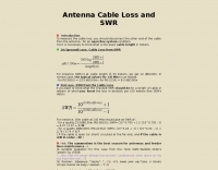
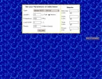 Calculate power loss depending on coax cable you use
 -
 The Resonant Feedline Dipole (RFD) HF antenna design utilizes a single piece of coaxial cable and a stranded wire section, forming a 1/4-wavelength radiator. This configuration, based on a 1997 ARRL Handbook design (page 20.17), functions by RF traveling on the inside of the coax shield and returning on the outside, creating the second half of the dipole. A choke wound into the feedline prevents RF current from flowing back down the feedline. Construction details include using RG-58a/u coax for a 75m version, with a 1/4-wavelength section of stranded wire soldered to the center conductor. The document provides choke dimensions for RG-213, RG-8, and RG-58 coax across 3.5 MHz to 28 MHz, specifying cable length and number of turns. Dipole dimensions are also tabulated for frequencies from 3.6 MHz to 28.4 MHz, listing overall length and individual leg lengths. Field tests included deployment near Bryson City at 5 feet off the ground and as a sloper during WCARS Field Day in Asheville, yielding successful local and regional contacts.
 -
 Selecting appropriate cabling for amateur radio installations, whether for antenna feedlines, control lines, or station wiring, is critical for optimal performance and safety. This resource provides access to a manufacturer specializing in a broad range of electronic and electrical cables, including options suitable for various ham radio applications. Their product line encompasses standard and custom cable solutions, designed to meet specific operational requirements for both indoor shack setups and outdoor antenna systems. The company emphasizes _proven quality_ and compliance, with products certified by the Canadian Standards Association (CSA), Underwriters Laboratories (UL), and Intertek (ETL). Their quality management system is registered to _ISO 9001:2015_, ensuring consistent product standards. They offer competitive pricing and utilize AI-logistic tools for reliable on-time delivery, serving customers globally with technical support. Access to detailed technical specifications and an online quote tool is available for registered site members, facilitating precise cable selection for projects requiring specific impedance, shielding, or environmental ratings.
 -
 Details Allied Wire and Cable's extensive product catalog, focusing on its role as both a distributor and manufacturer of specialized wiring solutions. The resource highlights the availability of electronic and electrical wire, various cable types, tubing, and pre-assembled cable solutions. It also specifies their capability in **custom cable design**, addressing unique requirements for specific applications. The site presents information on flexible cable options and a broad spectrum of wire and cable specifications, catering to diverse industrial and technical needs. It outlines the company's capacity to provide tailored solutions beyond standard off-the-shelf products, emphasizing their engineering and manufacturing expertise. Key offerings include **coaxial cable**, connectors, and general wiring components, positioning the company as a comprehensive source for connectivity infrastructure. The content implicitly supports applications ranging from industrial automation to specialized radio frequency installations.
 -
 Demonstrates the construction of a 144 MHz turnstile antenna, detailing its design for omnidirectional, horizontally polarized VHF operation. The resource outlines the physical dimensions and materials required, including specific lengths for the radiating elements and the use of _RG-58_ coaxial cable for phasing. It covers the assembly process, emphasizing the critical spacing and connection points to achieve the desired radiation pattern and impedance matching for the _2-meter band_. The article presents measured _SWR_ performance across the 144-146 MHz segment, showing a low SWR of 1.2:1 at 144.5 MHz, which is suitable for general VHF use. It compares the turnstile's performance to a 9-element Yagi, noting the turnstile's advantage in providing consistent signal strength from all directions without requiring a rotator. Practical application for local FM simplex and repeater operations is implied, offering a simple yet effective antenna solution for fixed or portable stations.
 -
 Hidden transmitter hunting, often called fox hunting or Amateur Radio Direction Finding (_ARDF_), presents a unique challenge for radio amateurs. This resource details the _PicCon_ controller, a specialized device designed to automate the transmission of signals for such events. It integrates with a standard radio transceiver, functioning similarly to a packet radio TNC, by controlling the Push-To-Talk (PTT) line and injecting audio tones or modulated CW Morse code into the microphone input. The _PicCon_ unit is field-programmable using DTMF tones received via the radio, storing all settings in EEPROM for power-off retention. Its compact design and low power consumption (a few milliamps from a 7-35VDC source) make it suitable for remote deployment. An onboard LED indicates operational status, and a push-button allows manual start/stop of transmissions without DTMF. Typically supplied as a kit, _PicCon_ includes a PCB, components, and a comprehensive manual (available in HTML, RTF, and PDF formats). The kit provides a six-conductor interface cable, but users must supply radio and power plugs due to varied configurations. Byon, _N6BG_, developed this controller, which is available from the Byonics website.
 -
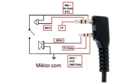 Speaker Microphone Pin Out, Dual PTT Switching,Programming Cables, SMA Antenna Connection, Extended Antenna Threads for Baofeng UV 3, UV 5 Series handheld transceivers
 -
 Live DX spots are presented through a _web cluster_ interface, utilizing both a world map and a Google Maps display for visualizing amateur radio propagation. The system provides real-time spotting data, enabling operators to track active stations globally. Users can observe current band conditions and station activity, which is crucial for optimizing contact strategies across various amateur bands. The platform's utility extends to contest operations and general DXing, offering a visual representation of where stations are being heard. While the primary function is DX spotting, the site also includes technical articles, such as instructions for interlocking two Flex Radios for single-transmitter compliance in contests, and a guide for constructing a simple **5KW** 1:1 balun for **160m/80m** dipoles using RG400 cable. This combination of live data and practical technical content supports both operational awareness and station improvement.
 -
 Demonstrates the adaptation and construction of a 7-element DK7ZB Yagi antenna for the 4-meter band (70 MHz), utilizing components from a defunct 2-meter CUE DEE Yagi. The resource details the modifications made to the original DK7ZB design to fit the shorter CUE DEE boom length, specifically adjusting element lengths for 6mm rod elements while reusing existing mounting holes for the reflector and last director. It provides precise element lengths for the reflector, dipole (12mm aluminum tube), and five directors, along with a note on cutting elements for transport. The article includes a 4NEC2 simulation file for performance analysis and an SWR plot, confirming the antenna's electrical characteristics. It also specifies the calculation for the quarter-wavelength matching cable using SAT752F coaxial cable, resulting in a 909mm length. Practical application is shown with the finished antenna in operation at JO20XC, listing several activated Maidenhead squares such as JO56PA and JP40KS, validating its effectiveness for portable 70 MHz operations.
 -
 Demonstrates the construction of a custom programming cable for Yaesu VX-7R and VX-5R handheld transceivers, enabling computer interfacing for memory management and frequency coverage adjustments. The resource details a six-transistor circuit design, powered by the computer's RS232 interface, utilizing readily available and inexpensive discrete components. It includes a complete bill of materials, specifying transistors like the _2N2222_ and _2N3906_, diodes, and resistors, along with a matrix board layout for compact assembly within a 75x50x25mm enclosure. The guide provides practical tips for working with matrix board, such as scoring and snapping, track cleaning, and component soldering order. It outlines the specific connection requirements for both the VX-7R (via Yaesu's CT-91 breakout lead with a 2.5mm stereo jack) and the VX-5R (via CT-44 or a four-section jack), detailing signal and ground pinouts. The author successfully tested three circuits, documenting the one with complete two-way communication, allowing users to program their rigs with software like _VX-7 Commander_ and achieve capabilities beyond commercial cables, including band adjustments.