Search results
Query: great
Links: 164 | Categories: 0
-
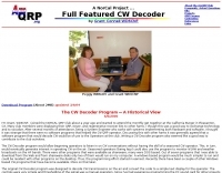 CW Decoder provides a robust solution for amateur radio operators aiming to decode Morse code directly on their computer. The software processes incoming audio, presenting the decoded CW as text on the screen, which can be particularly useful during crowded band conditions or for those refining their copying skills. Additionally, it offers the capability to generate a sidetone, allowing operators to monitor the decoded audio in real-time. The application features a **spectrum display** of the audio input, complete with a sliding cursor. This visual aid enables precise selection of a specific audio frequency for decoding, helping to isolate desired signals from QRM. My field experience with similar decoders confirms that a clear visual representation of the signal greatly improves decoding accuracy, especially when dealing with weak signals or multiple stations. Beyond decoding, the program integrates a **keying function**, allowing users to transmit CW directly from their keyboard. This feature supports full CW break-in operation, which is essential for efficient contesting and DXing, providing immediate switching between transmit and receive modes without manual intervention.
 -
 Sixty-four years of operating experience inform Glynn E. "Buck" Rogers Sr., K4ABT's, insights into the J-Pole antenna, which he describes as a direct descendant of the _Windom_ or _ZEPP_. His first article on the J-Pole appeared in HRC magazine in 1958, and he has since published numerous pieces in publications like CQ Magazine, consistently referring to the J-Pole as a Windom with a folded-back short section forming the parasitic element. He emphasizes that both the Windom and J-Pole are powerful multi-band antennas, performing exceptionally well at harmonics of their fundamental design frequency, and advocates for 50-ohm coaxial cable with a _BALUN_ at the feed-point to avoid RF energy losses. K4ABT details the J-Pole's features, noting its ease of erection, lack of radials, low angle radiation, greater bandwidth, and immunity to terrestrial noise. He highlights its suitability for local nets and distant repeaters, claiming more gain and durability than most ground planes, and its ability to meet stealth antenna requirements. The guide provides specific dimensions for 2-meter (145.000 to 146.000 MHz) and 6-meter (50.500 to 51.500 MHz) J-Pole antennas, including measurements for the long driven element, short tuning stub, and spacing. The construction section illustrates a modified feed technique using an SO-239 chassis-mount coax connector soldered into a copper tee, deviating from the usual hose clamp method. The author also discusses the use of _EMT_ (electrical metallic thin-wall conduit) as an alternative to copper in earlier days. He cautions against building a 75-meter J-Pole due to its impractical length, reinforcing the antenna's optimal application for VHF and UHF bands.
 -
 Great first time J-pole project. Covers most of the basics. This small and thin design also makes it good for several stealth applications.
 -
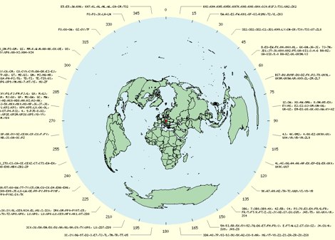 The page provides a tool to create a customized Ham Radio Az Map on the fly, with various dimensions available. It is a valuable resource for amateur radio operators to visualize and optimize pointing of directional antennas. The content includes maps for different regions, prefix maps, and world maps.
 -
 Real time tracking of an unlimited number of satellites, fast, accurate and easy to use. Automated FTP keps updates. Also support a great number of interface to control rotors azimuth and elevation plus frequency doppler shift. Since 2017 Nova is free to donwload and use. No support is given.
 -
 HamCalc is a free collection of calculators for radio amateurs include Antenna ERP calculations, Attenuators, Audio Filter design, Coil Winding, Decibels, Great Circles map and calculator, HF Filters, HF Traps, Metric conversions OP Amps QRA Locator to Latitude/Longitude, Radio Horizon calculator, Resonance Satellite orbit calculator Timer calculations (555 timer)Zener Diode calculations Download zip By G4VWL
 -
 The **DF9CY Three-Element Antenna for 28 MHz** details the modification of a commercial PAN International CB antenna to optimize its performance for the 10-meter amateur radio band. This resource provides specific design parameters, including a design frequency of 28.300 MHz, a usable bandwidth of 600 kHz, and a return loss better than 20 dB centered at 28.270 MHz. It also specifies a gain exceeding 7.5 dBi and a front/back ratio greater than 20 dB. The feeding mechanism utilizes a **gamma match**, with setup instructions provided for its positioning. Modifications involved shortening each element's end by 40 mm, a straightforward process due to existing screw holes. The author also recommends replacing the original screws with V2A stainless steel hardware to prevent oxidation and upgrading the SO239 connector to an N-connector for improved reliability. EZNEC simulation files are available, showing azimuth and elevation diagrams with good front-to-back ratio and around 10 dB vertical attenuation. The antenna has been in service since October 1998, demonstrating good performance with 90 watts and even 750 watts, facilitating contacts with all continents from a modest 9-meter height.
 -
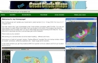 GCM is a freeware great circle map plotting software for windows, you can choose colours, scale, meridians, fields and or squares from the maidenhead locator system.
 -
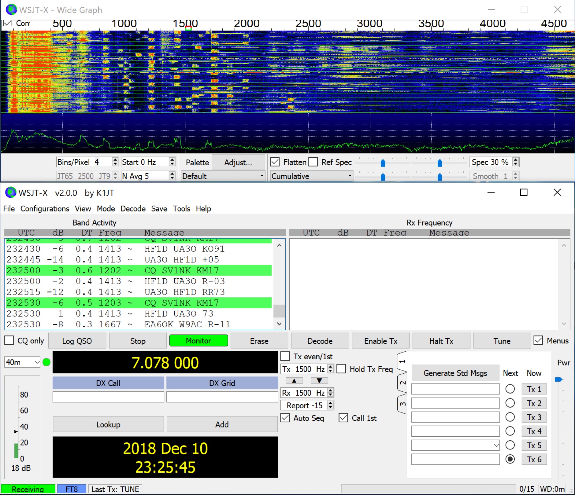 Facilitates reliable two-way communication under challenging propagation conditions, WSJT-X provides a suite of digital modes optimized for weak-signal operation across the amateur bands. These modes, including FT8, FT4, and Q65, are designed to decode signals significantly below the noise floor, enabling DX contacts, EME (Earth-Moon-Earth), and meteor scatter QSOs with modest station setups. The software supports various T/R sequence lengths and tone spacings, tailored for specific propagation phenomena and band characteristics, such as JT9 for MF/HF with **2 dB** greater sensitivity than JT65, and MSK144 for VHF meteor scatter. WSJT-X also integrates specialized tools like _MAP65_ for wideband EME reception with polarization matching to counter _Faraday rotation_, and QMAP for wideband Q65 reception with Earth-Moon-Earth Doppler correction. These companion programs extend the software's capabilities for advanced weak-signal work, particularly on VHF, UHF, and microwave frequencies. The project, maintained by Joe Taylor, K1JT, and the WSJT Development Team, is the official home and reference implementation for these weak-signal digital communication protocols. Recent releases, such as _WSJT-X 3.0.2_, introduce enhancements like the QMAP program, Q65 Pileup, and SuperFox mode, which offers approximately **+10 dB** system gain for Fox-and-Hound operations.
 -
 3 elements VHF Yagi homebrew antenna designed with YAGIMAX 3. Maximum forward GAIN is about 8,17 DBi. This antenna offering an effective radiation power 4 times greater of the transceiver output by SV1BSX
 -
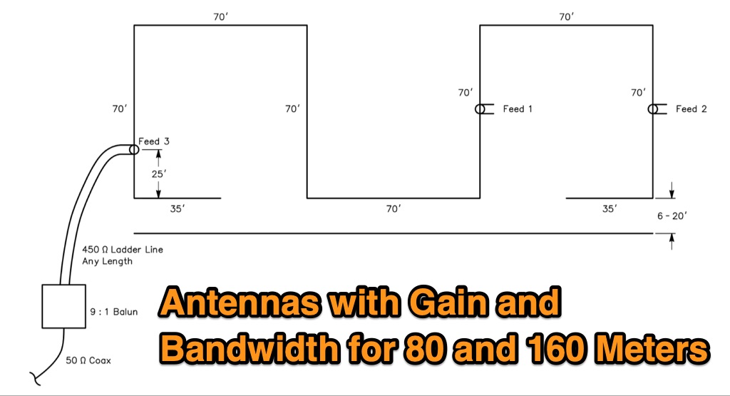 The Bruce array is a simple, often-forgotten wire antenna array that is advantageous for 80 and 160 meters, where typical gain antennas are very large. This bi-directional broadside vertical array is only 1\4 lambda high and does not require a ground system. It offers substantially greater SWR bandwidth than the half-square or bobtail curtain. A 4-element Bruce array used by N6LF showed a gain of about 4.6 dB compared to a 1\4 lambda vertical with 8 elevated radials, with a 2:1 SWR bandwidth greater than 400 kHz. The antenna is simple and its dimensions are flexible.
 -
 Home of the ultimate Ham Radio QSL Label Program! Quick QSL for DOS, featuring great color, dot matrix, laser, and inkjet printer support, a user-friendly interface,
 -
 Merging Internet technology with Amateur Radio holds great promise. This article discusses the authors experiences in putting several Internet Remote Base stations on the air. By Stan Schretter, W4MQ, Brad Wyatt, K6WR, and Keith Lamonica, W7DXX
 -
 Article by DK5WL describes a multi-band DX antenna for the 160m-40m amateur radio bands with low visibility but great performance for long distance communication.
 -
 provides much greater flexibility in the construction, analysis, and interpretation of radiating structures using a rewritten NEC module.
 -
 DarwinPsk is free to licensed ham radio operators and is a great application for PSK and RTTY communications under MacOSX
 -
 A woktenna. The collector and stand collapses in seconds, is aimable, portable, and gave terrific gain. This is a great little setup for a laptop on the go trying to get the distant wifi access.
 -
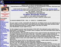 10 Meter WonderBar Antenna, present an SWR 1:1 over entire band, great DX, rotateable by hand, 8 ft long - build for about $20
 -
 F6EZX presents a detailed account of constructing a compact, multi-band _Levy antenna_ for portable holiday operations, specifically addressing issues with local QRM from a previous _Deltaloop_ setup. The article outlines the design criteria, including multi-band operation on 40m, 30m, 17m, 15m, 12m, and 10m, a symmetrical configuration to reduce interference, and a low take-off angle for DX. Construction involves 2x 10.3m radiating elements and a 15.3m open-wire feeder (ladder line) with 7cm spacing, made from 1.5mm2 copper wire and foam pipe insulation spacers. Theoretical calculations, referencing F9HJ's "_Les antennes Levy_" book, guide the determination of element lengths and feeder impedance characteristics, aiming for a good match across bands with a commercial antenna tuner. Initial field tests with the _VCI Vectronics VC300DLP_ tuner showed a 1:1 SWR from 80m to 10m, with some difficulty on 17m. The antenna, mounted as a 45-degree slopper with the high point at 12m, successfully facilitated DX contacts to South America, particularly Chile and Argentina, suggesting a lower take-off angle compared to the previous Deltaloop which favored Brazil. The Levy antenna significantly reduced TVI/RFI, attributed to its improved symmetry and greater distance from the QRA. While signal reports on 15m and 20m were 1-2 S-points lower than the Deltaloop, its performance on 40m and 30m was comparable, fulfilling the design goals for a portable, low-cost, multi-band solution.
 -
 The webs premier site for custom ham maps (azimuthal equidistant projection maps) and great circle bearing/distant charts for the radio amateur. Customized azimuthal equidistant projection maps and tables.
 -
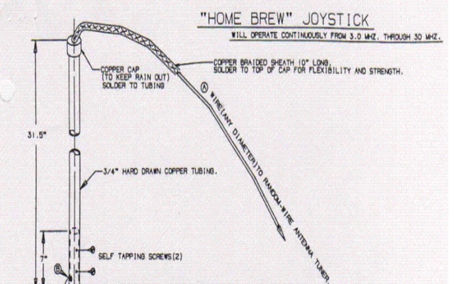 The Joystick antenna was used many years ago as an all band vertical HF antenna under restricted space situations that would cover from 80 meters thru 10 meters with a tuner and was a great commercial success Some hams even had success with it on 160 meters.
 -
 Frequency Filer is database program designed for people who use a great many different radio frequencies. It is primarily intended for amateur radio operators, short-wave listening enthusiasts and scanner users. The program makes it easy to keep all of your important frequency information in one place, displayed in a logical format to facilitate easy retrieval. Frequency information can be displayed as a list and can be viewed on a world globe. Other features include easy data backup and custom field names. Included is database import utility that can be used as a general file conversion utility. The globe display can also be used as general geographic aid for countries, cities, states, rivers, and lakes. You may even find your home town. Windows Shareware
 -
 This is a group for discussing Yaesu's great VX-7R handheld amateur radio.
 -
 Great first time J-pole project. Covers most of the basics. This small and thin design also makes it good for several stealth applications.
 -
 An antenna does not have to be resonant to work, as the primary reason for resonance is to eliminate the need for an impedance-matching device. A non-resonant wire dipole fed with open-wire line and an antenna tuner can function as an effective multiband antenna. Two wires are essential for powering an antenna, ideally with a balanced configuration like a dipole fed by parallel-wire line, though coaxial cable can be used with a 1:1 balun to mitigate RF feedback on the shield. Antenna gain is achieved by shaping and aiming RF energy, concentrating it in a particular direction, as seen in beam antennas or shaped radiation patterns of wire antennas. The function of an antenna tuner is to match the transceiver's 50 Ohm output to the antenna system's impedance, which can vary widely. Wire antennas do not always require center feeding; end-fed long wires or off-center-fed dipoles (Windom antennas) can be used, often requiring a counterpoise or radial system. Dipole antennas do not need to be perfectly horizontal; their legs can be bent, inclined, or even vertical, affecting feed point impedance. Vertical antennas shorter than a half wavelength necessitate a ground system, typically comprising radial wires, with more radials generally leading to greater efficiency. A 1:1 SWR indicates an impedance match but does not guarantee a good antenna, as an inefficient antenna with a poor ground system can still show a perfect SWR while wasting RF as heat. Always using the best feed line affordable is crucial for minimizing loss and maximizing RF signal delivery to and from the antenna.
 -
 Stryker Amateur radios offer great performance and unique features. We pride ourselves with offering affordable radios that are built with quality and performance in mind.
 -
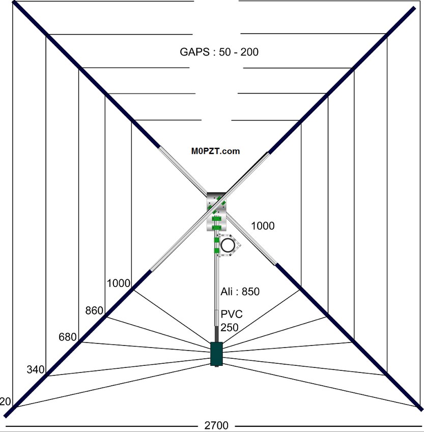 A 5-band (20m-10m) HF antenna - Just 7ft square and great for a small garden. Build it yourself for around 60 GBP.
 -
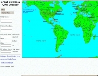 Interactive great circles and QRA Locator map
 -
 An experimental antenna, similar to the _TAK spiral antenna_, was evaluated for SWR response over the 7.0 to 7.3 MHz frequency range. The analysis presents specific results: beam length significantly affects SWR, with increased distance between spirals raising the resonant frequency; the combined length of antenna and hookup wire lowers the resonant frequency as it increases; and spiral diameter impacts bandwidth, with larger diameters yielding greater bandwidth. The design addresses the fixed beam length limitation of the commercial TAK antenna by introducing an adjustable version constructed primarily from PVC electrical conduit and water pipe, using 14-gauge aluminum wire. The resource includes a detailed mechanical design, construction steps, and a parts list. It also features a spiral antenna spreadsheet model for calculating design parameters like start point, pitch, safe edge, spoke length, and arm length, which aids in determining wire length and kerf cutting tables. Model verification involved constructing an antenna to specific parameters, with SWR tests conducted using an _MFJ Model 269_ antenna analyzer at 13 feet above ground with 60 feet of RG8 mini coax. Measurements showed that adjusting beam length from 27 to 37 inches shifted the resonant frequency by approximately 0.18 MHz. Further data compares 32-inch versus 48-inch diameter spirals, demonstrating increased bandwidth for the larger diameter. The model accurately predicted revolutions for given antenna lengths, pitch, and starting distances. The final design achieved a resonant frequency of 7.17 MHz, favoring the voice portion of the 40-meter band after adjustments.
 -
 GRIDX, a BASIC program that calculates grid squares and Great Circle headings and grid.exe, a grid locator calculator
 -
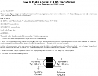 There are lots of good designs for matching transformers for receiving antennas. Make it yourself it's cheap and easy, and very high performance. This is the design used in the TRX-9 transformers.
 -
 Great shareware software collection for ham radio, includes prefix finders, locators,frequency generators and links to other ham radio software.
 -
 A full line of single-channel synthesized and crystal controlled vhf and uhf fm receivers. Great for repeaters, telemetry, and control applications.
 -
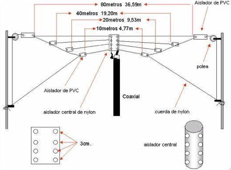 The Fan dipole antenna offer a easy to setup and efficient HF multiband antenna that does not require tuners or antenna switches, diagram by YC8PVU.
 -
 Great pages about KB1SG rhombic antennas collected by EI8IC.
 -
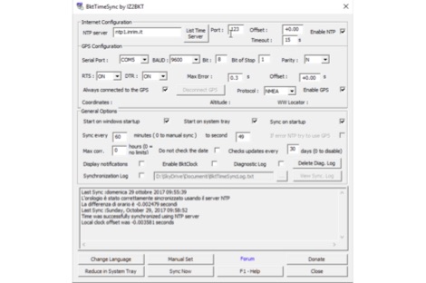 BktTimeSync synchronizes the PC time using an internet time server (NTP server) or a GPS receiver connected to USB, serial port or Bluetooth. Great for use with digital modes like FT8, JT65, JT9, JS8Call and others. For the operation of this program requires an active internet connection or a GPS receiver. This program works on all versions of Windows 32 or 64 bit
 -
 The Q-signal **QRP** signifies a request to reduce power, and in amateur radio, it defines operating with 5 watts or less for CW and 10 watts or less for SSB. This article addresses common inquiries from new hams regarding the practice, its benefits, and implementation methods. It explains how a 5-watt QRP signal, compared to a 100-watt signal, typically results in only a 13dB drop in signal strength, equating to about two S-units, still providing solid copy under most conditions. Hams choose QRP for various reasons, including seeking a greater challenge in DXing or contesting, reducing band interference, or enabling portable field operations with lightweight, battery-efficient equipment. A modern single-band CW transceiver, key, and antenna can fit into a pocket, offering receiver performance comparable to commercial rigs and extended operation on a small battery. This portability facilitates operations in remote locations where higher-power setups are impractical. Operating QRP can involve simply reducing power on an existing commercial HF rig or building a dedicated QRP transceiver from a kit, such as the **Wilderness Radio SST** with its 2-watt output and 15mA receive current draw. While SSB is viable, CW remains the most popular and efficient mode for QRP due to its superior signal-to-noise ratio. The article lists common QRP calling frequencies across 160m through 10m bands for both CW and SSB, and highlights organizations like QRP ARCI and NorCal that support the QRP community.
 -
 Constructing a functional spectrum analyzer for the 0-100 MHz range presents a significant challenge for radio amateurs, often requiring specialized components and careful calibration. This project details a homebrew spectrum analyzer design utilizing common integrated circuits like the _SA605D_ FM receiver IC and _MAR-6_ MMIC amplifiers, aiming for a cost-effective solution. The design incorporates a low-pass filter, RF amplification, a voltage-controlled oscillator (VCO) for downconversion, and multiple IF stages at 150 MHz and 10.7 MHz, with a resolution bandwidth (RBW) of 15 kHz. Critical components such as the _SBL-1_ mixer and varicap diodes are specified, alongside instructions for winding inductors and tuning filters. The analyzer's performance is discussed in terms of input level limitations, specifically the 1dB-compression point and third-order intercept point, to ensure accurate measurements and prevent component damage. The _SA605D_'s logarithmic Received Signal Strength Indicator (RSSI) output serves as the detector, driving the Y-input of an oscilloscope, while a _TL084_ op-amp generates the sweep signal for the X-input. Potential enhancements include adding a step attenuator, improving front-end filtering, and implementing switchable IF filters for variable RBW, allowing for greater versatility in analyzing RF signals.
 -
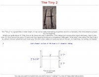 The "Tiny 2" is a great little 2 meter beam. It has some really interesting properties and it is a fantastic first time antenna project for the beginner.
 -
 A great source for hard to find HI END & power tubes & sockets, various capacitors, vacuum relays, various keys and paddles.
 -
 Bill Rinker, W6OAV, handcrafted this compact magnetic HF loop from copper and pvc plumbing supplies, a 12 volt motor, and some teflon sheets. He's had great reports with it.
 -
 This online calculator computes the great circle distance between two points on the earth's surface
 -
 Demonstrates the design principles and performance characteristics of **corner reflector antennas**, emphasizing their high gain and directional properties. It covers critical design factors such as the corner angle and the spacing between the radiating dipole and the reflector vertex. The resource explains how reducing the corner angle increases gain but lowers feed impedance, making matching more challenging. Practical angles of 90 degrees or 60 degrees are discussed, with 90 degrees offering easier impedance matching despite slightly lower gain. Details key design considerations, including reflector side length exceeding two wavelengths and reflector width greater than one wavelength for a half-wave radiator. It specifies reflector construction using wire netting, sheet metal, or parallel metal spines spaced less than 0.1 wavelength. The article provides a table with general dimensions for UHF and VHF bands, noting typical impedance values of 50 to 75 ohms and expected SWR of 1.7:1 on the lower band edge. Adjustable radiator-to-vertex spacing is highlighted as crucial for final tuning.
 -
 Analog circuit simulator for Windows (not a SPICE). A great tool for students, amateurs, as well as for experienced engineers. Free Demo.
 -
 This 4m Slim Jim Antenna is cheap and easy to build yet it greatly out performs the more usual dipole due to its low angle of radiation. An SWR of 1:1 is obtainable across the 4m ham radio FM band with a simple adjustment.
 -
 The Moxon Beam, introduced by L. Moxon (G6XN), is a compact 2-element Yagi featuring a radiator and reflector with reduced dimensions, approximately 75% the size of a full-size beam. This design utilizes bent element ends for capacitive loading, which is superior to inductive loading with coils, resulting in greater bandwidth and lower losses. DK7ZB details that while the gain is slightly lower (0.5-0.7 dB) than a full-size beam, the _Moxon_ offers an exceptional front-to-back (F/B) ratio of 30 dB or more on its design frequency, surpassing other 2-element beams. The article provides specific dimensions for building wire _Moxon_ antennas for bands from 30m down to 10m, and also mentions a 2-m-Moxon. Construction guidance includes using fishing rods for lightweight spreaders and an aluminum tubing spider for support. The resource highlights the utility of _Moxgen_ by AC6LA, a freeware program that simplifies Moxon beam design and generates EZNEC output files for further analysis and tapering modifications. DK7ZB emphasizes that the design frequency should be set at approximately one-third from the band's beginning to optimize SWR performance, as SWR tends to rise more significantly below the design frequency. The bandwidth for SWR < 1.5 is noted as sufficient for ranges like 28.0-28.7 MHz and 21.0-21.45 MHz when constructed with aluminum tubes, though wire beams exhibit a narrower bandwidth.
 -
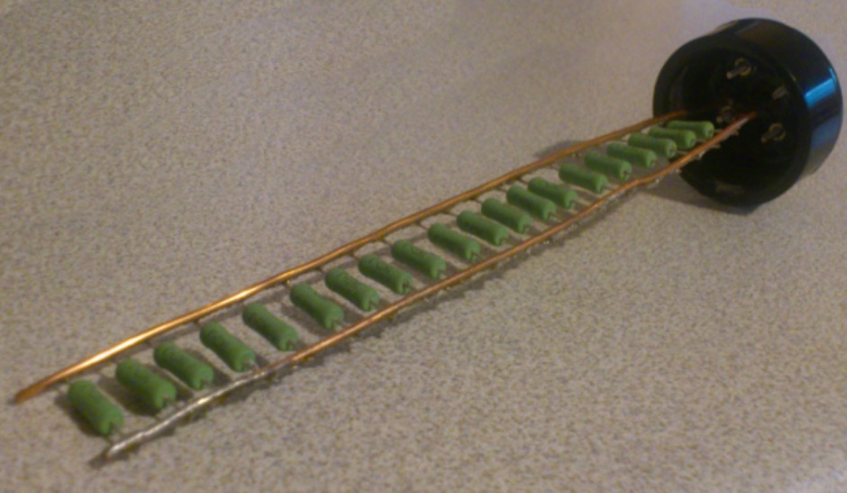 If your doing any home brewing gear for ham radio its a great idea to have a dummy load. This will to your radio be the perfect antenna...it will never radiate but your radio sees a perfect 50 Ohm impedance.
 -
 A javascript online calculator of bearing and distances by G4VWL
 -
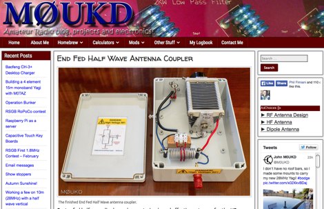 Centre fed half wave dipoles make great, simple and effective antennas for the HF bands. Sometimes however, the centre feed is not ideal. This great project will improve the overall antenna performance.
 -
 The YB7ZGP Pamaton Repeater operates on a frequency of 146.76 MHz, serving the Martapura District in Banjar, South Kalimantan, Indonesia. This VHF repeater provides local communication infrastructure for amateur radio operators in the region. The repeater's operation is managed by Syah Riyan, indicating a local amateur radio enthusiast or group maintains the station. Repeaters like YB7ZGP are critical for extending the range of VHF/UHF communications, allowing handheld and mobile transceivers to communicate over greater distances than line-of-sight. The 146.76 MHz frequency falls within the 2-meter band, a popular segment for local and regional amateur radio traffic, often utilized for emergency communications and general ragchewing. Information regarding the _Pamaton Repeater_ is presented on a blog platform, suggesting a community-driven effort to disseminate details about this local amateur radio asset.