Search results
Query: homebrew amp
Links: 47 | Categories: 0
-
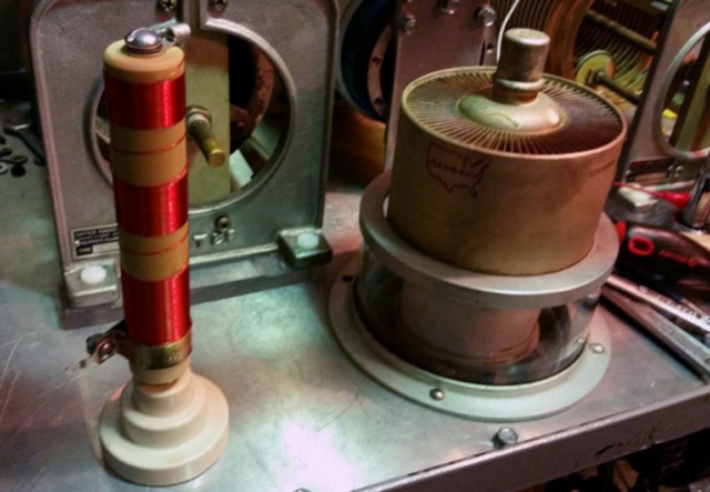
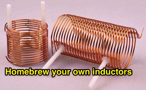 Cannot find the inductors you need for an antenna, a tuner or amplifier ? Build your own it is easy!
 -
 Amateur radio operators often seek reliable equipment for various modes and bands, from QRP operations to high-power DXing. Historically, Ten-Tec has been a notable manufacturer in the amateur radio market, known for its range of products including HF and VHF transceivers, RF amplifiers, and antenna analyzers. Their product line also encompassed specialized items such as QRP transceivers and kits, catering to enthusiasts of low-power communication, and antenna tuners for impedance matching. The company's offerings included test equipment vital for shack setup and maintenance, like SWR meters and RF analyzers, which assist in optimizing antenna systems and ensuring efficient power transfer. Additionally, Ten-Tec provided various accessories and components, supporting both commercial products and homebrew projects. The brand was recognized for its _made in the USA_ manufacturing, appealing to operators who prioritize domestic production. While the website currently displays limited product information, it mentions upcoming items like the _MODEL 594 PHOENIX_ and the _Tune-A-Tenna_, indicating potential future product releases.
 -
 The website https://www.qsl.net/dl5dbm showcases homebrew projects related to KW, 2-meter, 6-meter, antennas, amplifiers, preamps, power supplies, and more. It provides information and resources for radio amateurs interested in DIY projects and experimentation.
 -
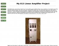 813 Linear Amplifier Project includes many schematics, drawind and assembling construction
 -
 The project details modifications to an ARK-40 QRP CW transceiver kit, specifically replacing its original thumbwheel frequency selectors with a **BASIC STAMP BS-II microcontroller** and an optical shaft encoder. The redesigned control circuitry outputs a BCD code to the ARK-40's synthesizer, enabling more convenient knob-type tuning. This modification significantly alters the user interface, moving from discrete frequency selection to continuous tuning. Operating frequency is presented on an LCD readout, offering two distinct display modes: a "bandspread dial" mode that simulates an analog dial scrolling across the display in 1 kHz increments, and a conventional digital readout with 100 Hz resolution. Pushing the main tuning knob toggles between these modes, providing both rapid band traversal and fine-tuning capabilities. The software for the BASIC Stamp is written in P-Basic, addressing the challenge of accurate analog dial simulation. Physical modifications include fabricating a custom PC Board for the STAMP, mounting it with an L-bracket to the optical encoder, and creating a new front panel. The front-mounted speaker was relocated to accommodate the new tuning knob and display, transforming the **ARK-40 transceiver** into a more user-friendly rig with its built-in CW keyer and 5 watts of power.
 -
 Presents a crystal-controlled CW transmitter design for the 40-meter band, delivering 5 to 7.5 watts output power. The circuit innovatively employs an _IRF510_ power MOSFET in the final amplifier stage, diverging from conventional bipolar transistors. This design offers high gain, nearly 90% efficiency, and robust resistance to high SWR, allowing 30-second key-down operation into an open circuit without damage. A critical aspect is the precise adjustment of the MOSFET gate bias via a 10K trimmer pot, _R10_, to maintain quiescent current between 5 and 10 mA, preventing thermal runaway inherent to bipolar devices. The prototype was constructed on a _Radio Shack universal board_ and achieved immediate operational success. The design requires a 15-volt Zener diode to protect the MOSFET gate from overvoltage. Component sourcing information is provided, including specific crystal frequencies (7.040 MHz or 7.122 MHz) available from _Dan’s Small Parts & Kits_ or Doug Hendricks. The fixed frequency can be slightly adjusted with a trimmer capacitor. A complete bill of materials, including resistor values, capacitor types, toroid specifications, and transistor part numbers, is detailed, alongside a clear schematic diagram.
 -
 The "EZ-Tuner" is a homebrew automatic legal-limit antenna tuner that covers all amateur HF bands from 160-10 meters. Using a T-network design and controlled by a BASIC Stamp BS2sx microcontroller, the EZ-Tuner will match at least a 16:1 VSWR for either unbalanced or balanced transmission lines.
 -
 Over 45 years of amateur radio experience inform the homebrew projects detailed on this personal website, with a particular focus on microwave frequencies. The site showcases a 24 GHz transverter and a more recent 47 GHz transverter, demonstrating practical construction techniques for extreme high-frequency operation. These projects often involve custom circuit design and careful component selection to achieve stable performance at millimeter-wave bands. Key projects include a _harmonic converter_ for frequency measurement and a tracking spectrum analyzer, essential tools for microwave experimenters. The site also documents a CW sidetone generator and a TX/RX sequencer, illustrating fundamental building blocks for radio equipment. Details on a digital frequency meter and an S-meter/dBm meter provide insights into test equipment construction. Specific achievements, such as a **24 GHz** tropo QSO with DK3SE in 2021, highlight the operational success of these homebrewed systems. The content reflects a long-standing dedication to self-sufficiency in amateur radio, providing practical examples for those interested in building their own gear.
 -
 Presents Telstar Electronics as a manufacturer specializing in amateur radio accessories, detailing its history since 1995 and highlighting key product offerings. The resource specifically mentions the _VoiceMax Transceiver Speech Processor_, designed to enhance audio fidelity and punch for SSB transmissions, and the _SkyWaveDX350_, indicating a focus on signal processing and reception improvement for DX operations. The company's product categories span ham radio accessories, microphones, and RF amplifiers, catering to various aspects of a station setup. The site implies a direct-to-consumer model for these specialized components, providing technical solutions for Icom, Yaesu, and Kenwood transceivers, and supporting homebrew enthusiasts with components and technical references.
 -
 Demonstrates the construction of a **homebrew spectrum analyzer** designed by Wes Hayward, W7ZOI, and Terry White, K7TAU, enabling radio amateurs to build a capable test instrument without significant expense. The resource details a _double-conversion superheterodyne_ circuit, employing intermediate frequencies of 110 MHz and 10 MHz, and covers essential blocks such as the time base, logarithmic amplifier, resolution filters, and local oscillators. It highlights the use of hybrid and monolithic ICs, including mixers, amplifiers, and VCOs, to simplify construction while maintaining performance. The design supports useful measurements in the 50 kHz to 70 MHz range, with methods outlined for extending capabilities into VHF and UHF. The authors emphasize that this analyzer, while simple to build, is intended for serious measurements, requiring careful control of signal levels to avoid spurious responses. It uses an oscilloscope for display, with specific instructions for calibration and adjustment of various stages, including the log amplifier and IF gain. The guide provides detailed schematics and component lists for each section, such as the 110 MHz triple-tuned band-pass filter, which achieved **90 dB** image rejection, a significant improvement over double-tuned circuits. Practical advice on alignment and troubleshooting is included, drawing on the authors' extensive experience in RF circuit design.
 -
 Details a practical QRP wattmeter construction, leveraging a simplified SWR meter design by JA6HIC. The project focuses on a forward-only power measurement circuit, providing a functional instrument for RF power levels from milliwatts up to 5 watts. It maintains a 50-ohm input and output impedance, suitable for typical QRP transceivers and antenna systems. The resource includes the schematic for the "VSW" (Very Simple Wattmeter) and outlines a six-step alignment procedure. This calibration process involves using a known RF source up to 5W, setting full-scale deflection, and marking power increments. It also addresses minimizing frequency effects on readings with a 100pF trimmer capacitor, noting that measurement error is highest at the lower end of the scale. Construction notes mention using a piece of RG-213 coaxial cable for the inductance and coupler, with the wattmeter assembled in early 2003. The author provides an example measurement showing 0.8W into a dummy load and 1W into a 3-element beam.
 -
 The EF0604S is a compact 4 elements yagi antenna plan for six meters band featuring 8.77 dBi gain and a front back gain of 17.89 dB. Article includes elements dimensions and spacing, along to pictures of some homebrewed examples.
 -
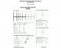 ON6MU optimized 6/9 element vhf yagui antenna with antenna schematic plan and pictures of homebrewed samples.
 -
 Homebrew with CF300 DGMF with about .24 dBD gain
 -
 VU2RAR basic VHF power amplifier suitable for 144-146 Mhz output power can vary from 3 to 25 Watts.
 -
 Constructing a functional spectrum analyzer for the 0-100 MHz range presents a significant challenge for radio amateurs, often requiring specialized components and careful calibration. This project details a homebrew spectrum analyzer design utilizing common integrated circuits like the _SA605D_ FM receiver IC and _MAR-6_ MMIC amplifiers, aiming for a cost-effective solution. The design incorporates a low-pass filter, RF amplification, a voltage-controlled oscillator (VCO) for downconversion, and multiple IF stages at 150 MHz and 10.7 MHz, with a resolution bandwidth (RBW) of 15 kHz. Critical components such as the _SBL-1_ mixer and varicap diodes are specified, alongside instructions for winding inductors and tuning filters. The analyzer's performance is discussed in terms of input level limitations, specifically the 1dB-compression point and third-order intercept point, to ensure accurate measurements and prevent component damage. The _SA605D_'s logarithmic Received Signal Strength Indicator (RSSI) output serves as the detector, driving the Y-input of an oscilloscope, while a _TL084_ op-amp generates the sweep signal for the X-input. Potential enhancements include adding a step attenuator, improving front-end filtering, and implementing switchable IF filters for variable RBW, allowing for greater versatility in analyzing RF signals.
 -
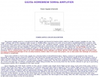
 Sales tubes for amplifiers like GS-23B,GS-31B,GS-35B,GU-34B,GU-43B,GU-74B,GU-84B. Include links to aplifier homebrew projects
 -
 An RF power supply for 144 MHz schematics and instructions
 -
-
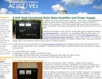 A solid state linear based on EB104 Motorola Engineering Bulletin by Helge Granberg. It uses 4 MRF150 FETs in push-pull parallel to acheive 600 Watts from about 6 Watts drive
 -
 VHF UHF Amateur radio antenna and antenna parts, accessories for homebrewers, antenna kits, tubes, antenna masts, antenna tripores, insulators, power amplifier mosfet, power splitters by I0JXX
 -
 Home made RF power amplifier for six meter band
 -
 Whether we are tuning up homebrew equipment, checking antenna VSWR, adjusting a linear amplifier, or just monitoring output power during a contest, almost all aspects of ham operation can use a power meter. Paul Wade W1GHZ
 -
 Demonstrates the construction and measurement of a single-turn HF receiving loop antenna, built from common materials like electrical conduit and lamp cord. The resource details the physical dimensions, including a 4-meter circumference, and calculates the theoretical inductance at approximately _6.4 uH_. It outlines a method for determining resonant frequencies across the 4-17 MHz range using a _C Jig_ and a _VR-500 receiver_, coupling the loop with a ferrite ring. The article also discusses the impact of receiver coupling on the loop's Q factor, noting a degradation in sharpness due to the transformer's reflected impedance. Analyzes the observed resonant frequency patterns, highlighting an unexpected rise in the loop's effective inductance at higher frequencies, particularly above 13 MHz. While some increase is attributed to distributed capacitance, the rate of rise suggests further investigation. The experimental setup provides practical insights into the challenges of maintaining high Q in simple receiving loops and offers a comparative reference for other homebrew antenna projects, such as those by _VK2TPM_.
 -
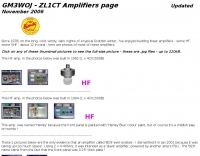
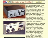 This homebrew six-meter linear amplifier started off life as a "junker" Alpha 76PA h.f. amplfier. Power output is 800W
 -
 The circuit is based on two AD8307 log amplifiers, which are connected to the forward and reflected ports on a directional coupler
 -
 Offer a wide range of homebrewing projects mainly for VHF UHF operations. From vhf antennas to preamplifiers, chargers and power supplies
 -
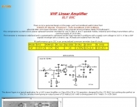 There is not a personal design on this page, just I've transfered useful notes from PHILIPS RF Bipolar Transistors - Data HandBook about BLY89C VHF Power transistor, which is very popular among Amateur Radio homebrewers
 -
 Presents a QRP AM/CW transmitter project specifically designed for the 10-meter band, utilizing a crystal oscillator and a collector-modulated AM oscillator. The design employs a 2N2219(A) transistor in a Colpitts configuration, generating 100 to 350 mW of RF output power depending on the 9-18 Volt supply voltage and modulation depth. Frequency stability is maintained by a 28 MHz crystal, with fine-tuning possible via a Ct1 trimmer capacitor for approximately 1 kHz adjustment. The resource details the RF oscillator stage, implemented with a 2N2219 NPN transistor, emphasizing frequency stability and low power dissipation. It also covers the amplitude modulation stage, managed by a 2N2905 PNP transistor, which impresses audio information onto the carrier. Selective components (C3, C4, C7, C5) enhance voice frequencies within a +/- 5 kHz bandwidth, and modulation depth is controlled by R2 and R3. The project includes a 3-element L-type narrow bandpass filter (Ct3, L3, C10) to suppress harmonics and ensure a clean output signal. The project provides a complete schematic diagram, a comprehensive parts list including specific capacitor, resistor, and inductor values, and construction notes for the coils (L1, L2, L3). It also offers practical advice on enclosure requirements, suggesting an all-metal case or a PVC box with graphite paint for RF shielding. Operational parameters such as current draw (27mA@9V to 45mA@16V) and input impedance (50 Ohms) are specified, alongside guidance on antenna matching and the importance of a valid amateur radio license for 10-meter band operation.
 -
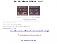
 Operating on the 2200m band (135.7-137.8 kHz) often presents challenges for amateur radio transceivers, which typically exhibit poor receiver performance at these very low frequencies. This project addresses the issue by providing a design for a dedicated 137 kHz antenna preamplifier, specifically tailored to improve signal reception for radios such as the _Yaesu FT-817_. The preamplifier circuit utilizes a low-noise FET input stage, crucial for minimizing self-generated noise and maximizing the signal-to-noise ratio from weak LF signals. The design includes a detailed schematic, component values, and construction notes, enabling homebrewers to build a functional unit. The goal is to achieve significant gain, making the faint signals on 2200m more discernible and improving overall band usability. Key design considerations include impedance matching to typical antenna systems and ensuring stable operation across the narrow LF segment. The circuit aims for a **low noise figure** and sufficient amplification to overcome the inherent limitations of general-purpose HF transceivers when operating below **200 kHz**.
 -
 The resource details the construction of a homebrew 50-watt FET amplifier, based on Don W6JL's _QST Homebrew contest_-winning design from 2009. It functions as an afterburner for QRP transceivers, providing a **12dB** power lift. The amplifier utilizes IRFZ24N FETs and covers the 80, 40, 30, and 20-meter bands, with the 20m LPF extending to 17m. Key technical aspects include an FT37-43 transformer for the input network, a relay-switched 3dB pad for lower bands controlled by an _Arduino Nano_, and an RF-actuated T/R switch. The LPF board integrates four relay-switched filters rated for 50 watts, using capacitors with a minimum 250VDC rating. Performance measurements indicate a power gain ranging from **4.4dB** on 20m to 8.1dB on 80m, with a required drive power of approximately 5 watts. The article also discusses thermal management, current limiting considerations, and component sourcing.
 -
 In this PDF article Zack Lau describe how to homebrew a four element yagi beam antenna for 50 MHz band, including how to build mounting blocks and tubing clamps to hold elements.
 -
 Homebrew Tubes/LDMOS amplifiers, Antenna, accessories, adventures in 9Q, DX, UN missions, Contests, and more.
 -
 This online project guide details the construction of a homebrew boom microphone system. It details the assembly of a microphone shell from a 3/4" PVC pipe section and an end cap, requiring a drilled hole for a snug fit of the electret or condenser mic element. The internal wiring schematic specifies a **2.2 K** resistor and a **47 uF** polar capacitor for signal conditioning, with a circuit diagram provided for integration with IC-706 series transceivers. The guide outlines the use of CAT-5 cable for internal connections, incorporating strain relief at the rear of the mic shell, and an inline 3.5 mm jack to facilitate an external _PTT_ line, designed for a foot-mounted switch. Further construction involves fabricating a microphone shock mount from a 2-inch PVC connector, detailing the creation of four "fingers" and the insertion of screw-eyes for attaching elastic bands, which are twisted 180 degrees for tensioning and vibration isolation. A foam wind screen is also incorporated into the microphone assembly, secured with adhesive. The boom arm itself is repurposed from an articulated architect lamp, with the original lamp assembly converted into a **60 watt** resistive load for testing power sources. Microphone cabling is secured to the boom arm using wire ties, ensuring sufficient slack at hinge points to maintain articulation. The boom base is mounted to a bookshelf, requiring specific positioning to achieve proper microphone placement in front of the operator. Performance evaluation of the microphone system is conducted through on-air audio signal reports from other amateur radio operators. DXZone Focus: Online Project Guide | Boom Microphone Construction | Electret Mic Element | PTT Line
 -
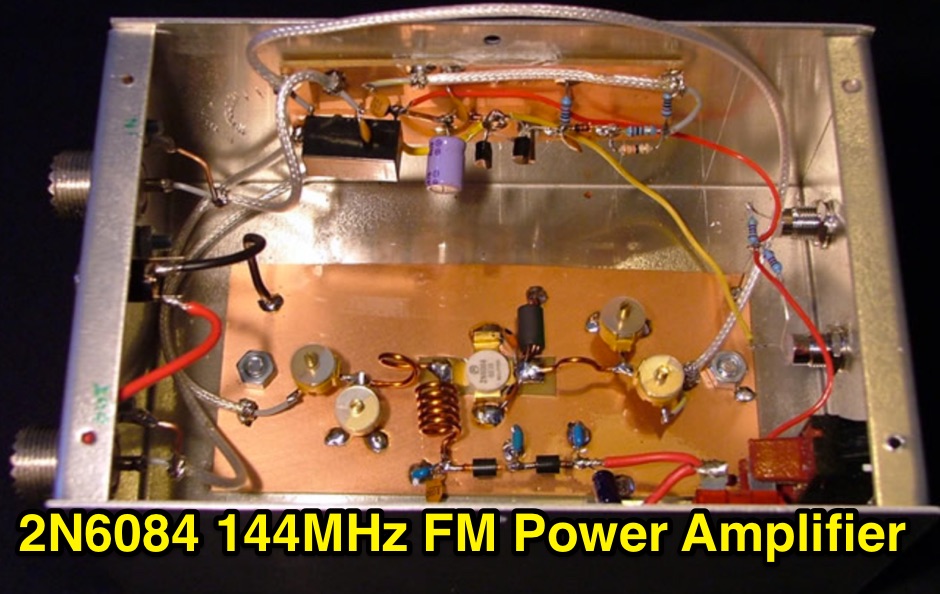 A 144MHz FM class C RF Power Amplifier based on a 2N6084 RF transistor, that can produce 50w output max
 -
 Constructing a high-performance RF spectrum analyzer up to 1000 MHz requires careful attention to component selection, shielding, and circuit isolation. This resource details a project that improves upon the _Spectrum Analyzer for the Radio Amateur_ design by Wes Hayward (W7ZOI) and Terry White (K7TAU), incorporating ideas from Scotty Sprowls' project, particularly his 1013.3 MHz IF bandpass cavity filter. The analyzer utilizes a Mini-Circuits SRA-11 mixer with a sweeping local oscillator from 1013 to 2013 MHz, feeding into a 4-pole copper pipe cavity filter. The design employs a second SRA-11 mixer with a fixed 1024 MHz LO to produce a 10.7 MHz final IF. This signal then passes through narrowband resolution filters and is processed by Analog Devices AD603 and AD8307 ICs for IF amplification and logarithmic detection, driving an oscilloscope in X/Y mode. The project emphasizes modular construction, using salvaged components and double-sided FR4 material for PCBs, with critical notes on minimizing spurious images through effective shielding and proper voltage regulation for each module. Key components include a Z-Communications V585ME48 VCO for the first LO and a Z-Comm V583ME01 VCO controlled by a Motorola MC145151 PLL for the second LO. An optional Hittite HMC307 step attenuator and K&L 5L121-1000/T5000-O/O low-pass filter manage RF input. Tuning procedures for the 10.7 MHz IF resolution filter are also detailed, showing before-and-after spectrum views.
 -
 Designing and constructing a two-element receiving loop antenna array for HF operation involves specific considerations for achieving high directivity and noise reduction. This resource details a homebrew system comprising two 30-inch diamond-shaped loops, spaced 20 feet apart, which are fed through mast-mounted preamplifiers and passive signal combiners. The operational principle relies on adjusting phase delays between elements via precise _Belden 8241_ coaxial cable lengths, optimized for specific bands from 160m to 20m. Performance data, derived from _EZ-NEC_ modeling, illustrates consistent 90° azimuth-plane beamwidth and low take-off angles across the target bands, with _Receiving Directivity Factor_ (RDF) values comparable to a 300-foot Beverage antenna. The article presents detailed elevation and azimuth plots for 20m, 30m, 40m, 80m, and 160m, demonstrating the array's ability to provide strong response at low DX angles while also supporting _NVIS_ signals. Key components like the _DX Engineering RPA-1_ preamplifier and _DXE RSC-2_ signal combiner are discussed, alongside the importance of impedance matching to preserve antenna patterns. The construction emphasizes self-contained elements that do not require ground radials, offering a compact solution suitable for suburban environments and stealth installations, with a focus on optimizing receive performance independently from transmit antennas.
 -
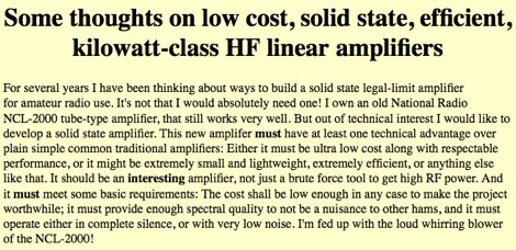 Thoughts build a solid state legal-limit amplifier for amateur radio use.
 -
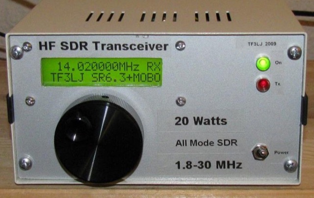 This project describes a DIY all band HF SDR transceiver. Built around a Softrock 6.3 kit, it boasts a 20W homebrew amplifier and ATmega168 microcontroller for USB control. An LCD displays frequency, power, and SWR. Automatic LPF selection and SWR protection enhance functionality. Compatible with Rocky and PowerSDR software, this project provides a cost-effective and powerful HF SDR transceiver for hobbyists.
 -
 Operating in a Single Operator Two Radios (SO2R) setup, especially with beverage antennas, often exposes the receiving radio's front-end to significant RF energy from the transmitting radio. This resource details a practical, homebrew receiver protection circuit designed to mitigate this risk. The core of the design involves a non-inductive 2W 22 Ohm carbon composition resistor in series with the RX antenna line, followed by two stacks of four fast-switching diodes (e.g., _1N914_) configured in opposite polarizations. This arrangement effectively clamps the incoming voltage to approximately 2.8 V peak-to-peak, safeguarding sensitive receiver input components. The series resistor plays a crucial role by absorbing excess power, preventing the diodes from exceeding their current ratings and potentially failing open, which would leave the receiver unprotected. The author, _N4KG_, measured up to 50 watts of coupled power between 80M slopers on the same tower, highlighting the necessity of such protection. The design is presented as a cost-effective solution to prevent damage to receiver input transformers, with the author noting successful protection of a receiver even after a resistor showed signs of overheating. This simple circuit can be integrated via a transverter plug, offering a robust defense against high RF input.
 -
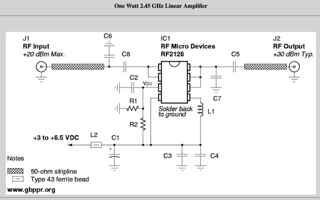 This will show you how to add a RF power amplifier to your Proxim Symphony for under $50. The cost is reduced by using the existing components on the Symphony, such as the PIN diode switch, and just inserting a higher power final amplifier. Increase the RF output power of your wireless network card to 1 Watt.
 -
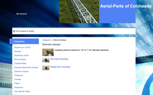 Online antenna parts store, providing many accessories for amateur radio antenna homebrewing. Boom joiners, aluminium parts, elements clamps, filters, ferrites, fasteners, plasti caps, dipole elements. Based in UL
 -
 A picture gallery of a home-brew RF Power amplifier made with 3CX3000
 -
 Amateur radio blog about Homebrew equipment,ham radio antennas, satellites, QO-100 operations, rf amplifiers, 2m ldmos amplifier, 70cm ldmos amplifier, 23cm ldmos amplifier
 -
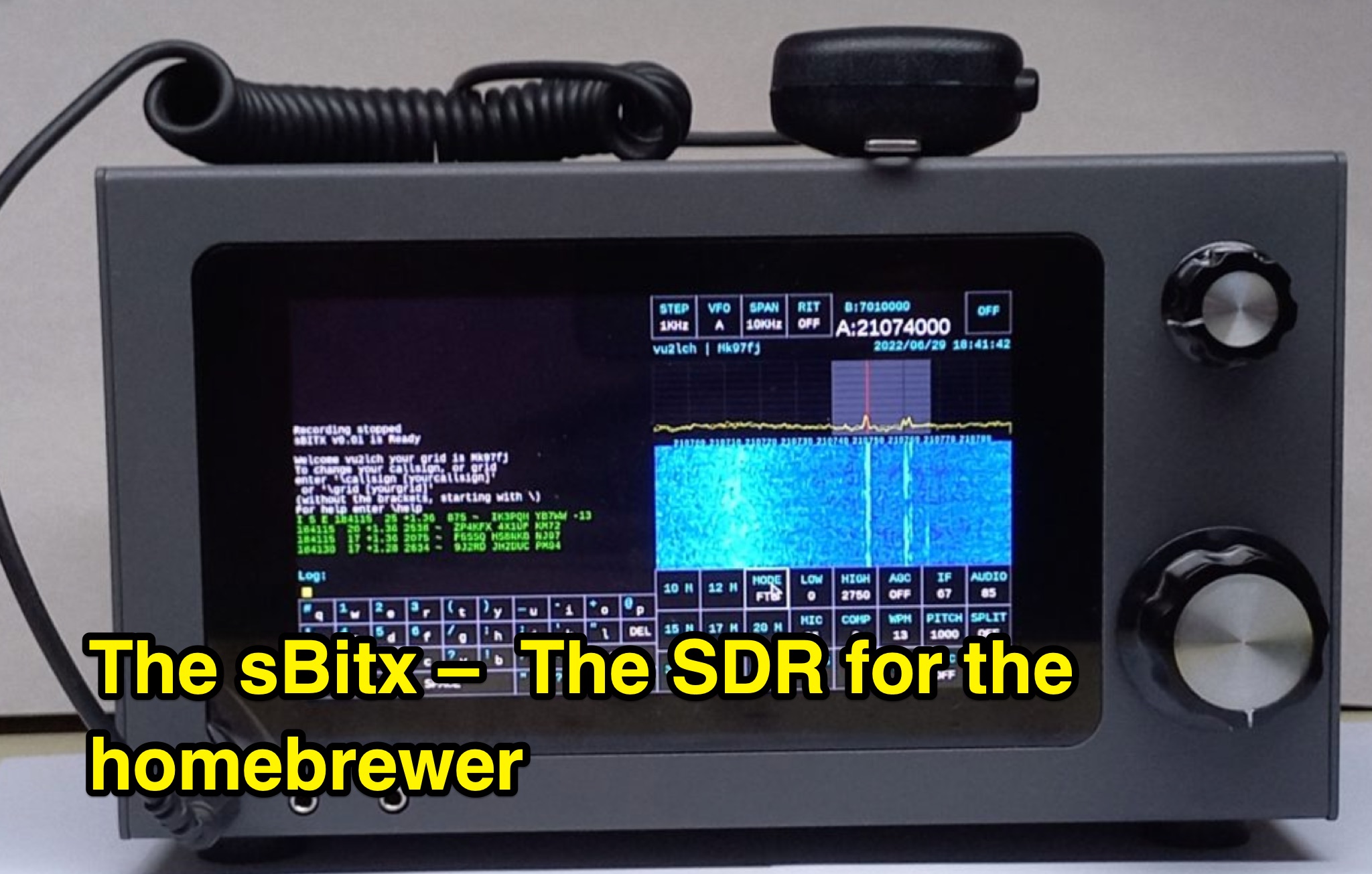 This page, authored by VU2ESE, delves into the sBitx, a Software-Defined Radio (SDR) designed for homebrewers. The content covers the hybrid SDR circuit, software, user interface, hacking/modifying the sBitx, performance, and more. It explores the various components of the sBitx, including the exciter, filters, amplifiers, digital circuit, and modems. The page aims to provide information and guidance for hams interested in building their own SDR. Readers will learn about the capabilities, features, and adaptability of the sBitx, making it a valuable resource for DIY radio enthusiasts.
 -
 This article details the design and construction of a compact 20-meter QRP SSB transceiver by Pete Juliano, N6QW, measuring just 2 x 4 x 2 inches—small enough for a shirt pocket. Inspired by a 1963 QST design and refined from a prior version, it employs bilateral circuits, a 4.9152 MHz homebrew crystal filter, switched-crystal VXO for 60 kHz coverage (14.160-14.220 MHz), and standard components like ADE-1L mixers and IRF510 PA for 1W output. Key innovations include a double-sided PCB skeletal frame for shielding and isolation, Vectorboard sub-assemblies, and ultra-miniature relays. The bilateral receiver/transmitter shares stages, omitting AGC for simplicity, while a W3NQN LPF and optional 10W external amp enable DX contacts. Tune-up focuses on crystal matching and bias for linearity. Videos on YouTube demonstrate performance, confirming excellent stability and audio. Total cost nears $100, prioritizing portability over features like CW.
 -
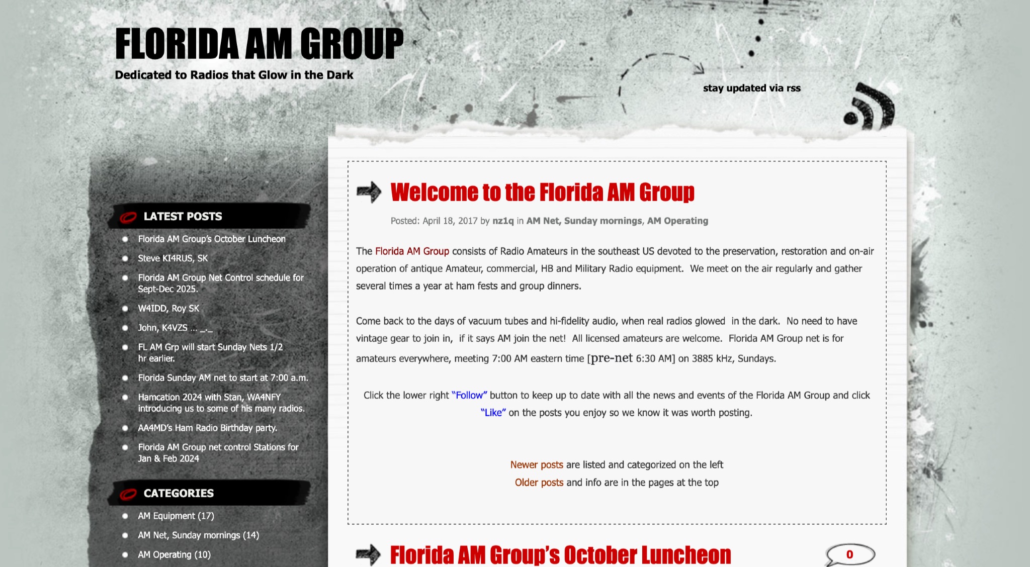 The Florida AM Group operates a weekly Amplitude Modulation (AM) net on 3885 kHz every Sunday morning, with a pre-net starting at 6:30 AM Eastern Time and the formal net at 7:00 AM. This group focuses on the preservation, restoration, and on-air operation of antique Amateur, commercial, homebrew (HB), and Military Radio equipment, emphasizing **Amplitude Modulation** (AM) mode. Participants are encouraged to use AM mode, regardless of whether they possess vintage gear, fostering a community around classic radio operation and the distinctive high-fidelity audio associated with **vacuum tube** equipment. The net utilizes NetLogger software for check-ins and round table management, providing a structured environment for participants. The group regularly publishes net control schedules, listing operators like NZ1Q, K1HH, and W3XM, and organizes various in-person events such as Hamcation gatherings, luncheons, and boat anchor swap meets. These activities facilitate eyeball QSOs and equipment exchanges, reinforcing the community aspect beyond on-air operations. The Florida AM Group also provides contact information for net control volunteers and shares news, including SK (Silent Key) announcements for members like Steve KI4RUS and Roy W4IDD, highlighting the group's long-standing camaraderie and shared passion for AM radio.