Search results
Query: line a
Links: 433 | Categories: 46
This query is too generic. Please try adding an additional term to focus your research.
Categories
- Antennas > Collinear
- Antennas > Feed Lines
- Antennas > Resonant Feedline Dipole
- Internet and Radio > Online Receivers
- DX Resources > DX Peditions > 2014 DXpeditions
- Radio Equipment > HF Amplifiers > Acom 1010
- Radio Equipment > HF Amplifiers > Ameritron AL-811
- Manufacturers > Amplifiers
- Shopping and Services > Regional > Australia
- Antennas > Baluns
- Manufacturers > Baluns
- Technical Reference > Radio Frequency Interference > BPL
- Software > Browser extensions
- Technical Reference > Calculators
- DX Resources > Callsigns
- Shopping and Services > CB Radio Stores
- Internet and Radio > Chat
- DX Resources > Contest > Contest Rules
- Software > Databases
- Operating Aids > Distance & Bearing
- Software > Filter Design
- Shopping and Services > Ham Radio Stores
- Radio Equipment > HF Amplifiers > Heathkit SB-200
- Radio Equipment > HF Amplifiers > Heathkit SB-220
- Internet and Radio
- Radio Equipment > HF Amplifiers > Kenwood TL-922
- Software > Log Analysis
- DX Resources > Logs
- DX Resources > Logs Search Services
- Antennas > Maria Maluca
-
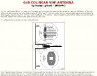 Building details of a VHF colinear antenna with 6 db gain
 -
-
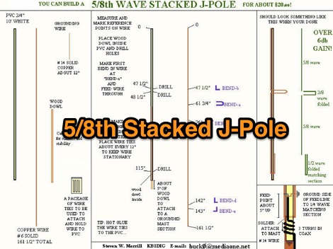
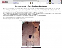
 Great first time J-pole project. Covers most of the basics. This small and thin design also makes it good for several stealth applications.
 -
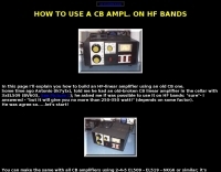 how to modify a Cb linear amplifier to use in HAm HF band
 -

-
 This compact little amplifier is the brain-child of Pat Murdoch, ZL1AXB, in Auckland, New Zealand. It is only 11" wide, 4" high, and 9" deep. Operates for 40, 20, 17, 15, 12, and 10m
 -
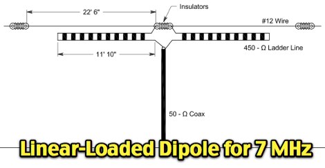 A short but efficient dipole for 40 meters band
 -
 160 meter linear loaded voltage fed T antenna
 -
 Hear VLF audio from NASA online VLF radio receiver in Huntsville, Alabama.
 -
 RF Concepts manufacturer of Alpha Linear Amplifiers, amateur radio RF power amplifiers, commercial power amplifiers, power meters and dummy loads.
 -
 Use 4CX10000D / 8171, RF output power of 11 KW in key-down carrier on all bands. Power was measured with a Bird 4712 wattmeter and a 25 KW slug
 -
-
 How do you fit a full length 160 meter antenna into a 40 foot deep yard?
 -
 Determining the actual need for an antenna tuner often hinges on the specific antenna and feed line configuration in use. While many hams believe a tuner is always essential, its primary role is to present a 50-ohm impedance to the transceiver, not to "tune" the antenna itself. For instance, a resonant dipole fed with _coaxial cable_ at its design frequency typically requires no tuner, as the feed line impedance closely matches the radio's output. However, operating a non-resonant antenna, or using a resonant antenna on multiple bands, frequently necessitates a tuner to manage high Standing Wave Ratio (SWR) on the feed line. The article clarifies that a tuner placed at the transceiver only matches the radio to the feed line, not the antenna to the feed line. For maximum efficiency with a non-resonant antenna, an _automatic antenna tuner_ (ATU) or a remote tuner placed at the antenna feed point is often more effective, minimizing losses in the feed line. The discussion also touches on the practical implications of SWR, noting that modern transceivers often fold back power at high SWR, making a tuner a practical necessity to achieve full output power, even if the antenna itself is not perfectly matched.
 -
 Over 25,000 amplifiers and sub-assemblies were produced by Angle Linear for the communications industry over a 40-year period. The company specialized in **high-linearity RF products**, focusing on preamplifiers, bandpass filters, and receiver multicouplers. Specific product lines included PHEMT and GaAs FET preamplifiers, offering both quadrature and single-ended configurations for various signal levels. The offerings encompassed coaxial and combline bandpass filters, along with integrated filter-preamplifier assemblies. The company also provided custom RF assemblies, addressing applications such as MRI preamplifiers, passive radar, and EME (moon bounce). Their product range covered VHF and UHF frequencies, including specific designs for 2m, 70cm, and 23cm bands, often featuring high IP3 performance. Technical documentation, such as filtering application notes and duplexer theory, was also associated with their product offerings.
 -
 This Vertical antenna design by David Reid for lower bands focuses on achieving effective DX communication by optimizing the antenna low-angle radiation for long-distance contacts. The design incorporates techniques like linear loading and capacity hats to reduce the antenna's height while maintaining performance, especially on 40m and 80m bands. Building a solid ground plane and using quality materials ensure efficiency and durability. Although vertical antennas can be complex to build, this project simplifies the process, making it accessible for ham operators seeking strong, reliable signals.
 -
 This page details the construction of an easy-to-make collinear 360 degrees omni-directional, vertically polarised, antenna for 802.11b/g wireless networking.
 -
 Online computer-based training for the amateur radio written exams
 -
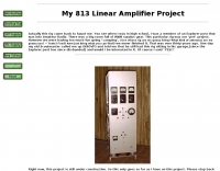 813 Linear Amplifier Project includes many schematics, drawind and assembling construction
 -
 Listen to Boston Fire Department live scanner feed
 -
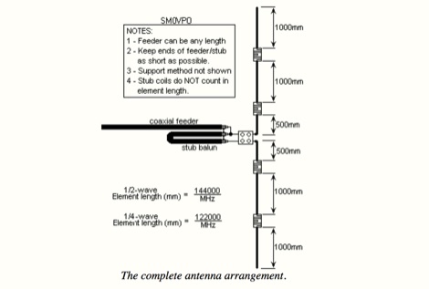
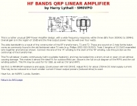 HF Bands QRP linear amplifier by SM0VPO
 -
-
 *One single page* gives you an immediate overview of current shortwave propagation conditions at your location.
 -
 Presents the KE4UYP linear-loaded vertical antenna design, which introduces very little loss on 80 or 160 meters, achieving an overall radiation efficiency of 80% to 85%. This design addresses common pitfalls of traditional base-fed verticals by placing the majority of the current at the top of the antenna, eliminating the heavy reliance on extensive ground radial systems. The author's initial 10-meter model, only three feet tall, yielded 5/9 signal reports to Anchorage, AK, and Europe, confirming its effectiveness. The antenna incorporates both vertically and horizontally polarized radiators, with a 1/4 wavelength horizontal counterpoise located at the feed-point, near the top, to create an almost totally omnidirectional pattern with high wave angle horizontally polarized radiation. This dual polarization ensures even illumination across all take-off angles, making it effective for both local contacts and **DXing**. The vertical element is linear loaded, adding capacitance reactance and making it longer than the horizontal element to achieve resonance and raise the feed-point impedance to 50 ohms. Fine-tuning the antenna requires careful adjustment, as tower reactance can vary. The article suggests starting with 80 feet for 80m and 170 feet for 160m for the vertical wire, then trimming for resonance. Bandwidth specifications include 300 kHz under 2:1 **SWR** on 80m and 100 kHz on 160m when suspended between trees, or 150 kHz on 80m when side-mounted on a tower.
 -
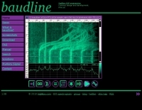 A Linux based FFT spectrum analyzer designed for time-frequency browsing and scientific data visualization. Oscilloscope waveform, statistical histogram, accumulated spectral trace,Weak Signal reception, continuos data logging, FFT Analyzer and specialized measurement windows.
 -
 A free computer aided design program to help users without special expertise in filter design to create filters using Linear Technology's monolithic filter ICs. With FilterCAD, you can design lowpass, highpass, bandpass and notch filters
 -
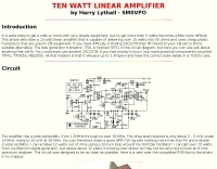 This article describes a 10 watt linear amplifier that is capable of delivering over 15 watts into 50 ohms and uses cheap plastic transistors that are used in CB equipment. by Harry Lythall - SM0VPO
 -
-
 This rugged antenna, an omnidirectional collinear, is capable of surviving harsh environments. It's a good choice for repeater installations and can be top, or side mounted to the tower by WA6SVT
 -
 The _Astron RS35m Power Supply Schematic_ provides a detailed circuit diagram for this popular linear power supply, focusing on the rectifier and pass transistor stages. It presents the AC input and DC output sections, illustrating the component layout and interconnections critical for understanding its operation. The schematic is enhanced with specific annotations derived from the December 2005 QST "Hands-On Radio, Experiment #35 Power Supply Analysis." These notes offer insights into the circuit's functionality and potential analysis points, making the diagram more instructive than a bare schematic. The resource serves as a practical reference for hams interested in the internal workings or maintenance of the _Astron RS35m_ unit. This document specifically highlights the key components responsible for voltage regulation and current delivery.
 -
 Contain schematic diagram of many different radio, and some operations instructions.
 -
-
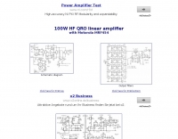 Based on Motorola MRF454, schematics and component list
 -
 HF VHF UHF amplifiers, designed by hams for hams, and morse keys manufacturer
 -
 Presents a catalog of **QRP** transceivers, antenna tuners, and related accessories for amateur radio operators. The product line includes the ZM-2 antenna tuner, designed for efficient impedance matching across HF bands, and the NW-series QRP transceivers, offering low-power CW operation. Additionally, the site details various ladder line insulators and specialized connectors, emphasizing robust construction for field deployment and home station use. Each product listing provides specifications, operational parameters, and pricing information. Compares the features of different **QRP transceiver** models, such as the NW-40 and NW-20, highlighting their respective band coverage and power output capabilities. The ZM-2 tuner's performance is detailed with typical SWR reduction figures for various antenna types, demonstrating its utility for portable and fixed stations. Customer testimonials and product images illustrate the practical application and build quality of EMTECH's offerings, providing insights into their durability and ease of integration into existing amateur radio setups.
 -
 A 144 MHz kilowatt amplifier project details the construction and performance of a high-power VHF linear using the GU74b tetrode. This Russian tube, equivalent to the Svetlana 4CX800, is noted for its conservative datasheet ratings, performing closer to 800-1000W anode dissipation in practical applications. The design prioritizes compactness and achieves 1.2 kW output with only 20W of drive power, demonstrating a 70% efficiency at 2.5 kV plate voltage. The amplifier has been successfully deployed in demanding _EME_ (Earth-Moon-Earth) operations since June 1994. Challenges encountered during development included achieving stability with a grid-1 input configuration. The author, _CT1DMK_, opted not to publish the full design due to its complexity, suggesting it might be difficult for less experienced builders to replicate successfully. However, he invites direct contact for those with specific interest in the design. Future plans include a "144MHz GS35b compact amplifier" project, promising another kilowatt-plus design. This resource offers insights into high-power VHF amplifier construction and the practical application of specific power tubes.
 -
 4CX250B X2 K2RIW style 2m amplifier
 -
 Ham Radio Audio Stream: listen live to German amateur radio repeaters.
 -
 The 30/40 meter **vertical antenna** project by IK4DCS details the construction of a shortened, self-supporting design, reaching a total length of 5 meters. The antenna incorporates a linear loading section and a coaxial cable trap for 30 meters, based on the "Antenne Volume 2°" text by Nerio Neri (page 223). The design uses six radials, three for each band, positioned at approximately 90° inclination and at least one meter above the roof or ground, connected via a 1:1 balun at the feed point. Mechanical construction utilizes aluminum tubing, with a 2.30-meter primary radiator section (30 mm diameter) joined to a second part using a Teflon insert and a PVC sleeve for rigidity. The linear load, approximately 3.70 meters long, accounts for a 30% physical shortening of the quarter-wave element. A capacitive load, made from three 50 cm radials, is integrated into the 40-meter top section for fine-tuning. Final adjustments involved radial inclination for 40 meters, as initial testing showed increased SWR and interference on 30 meters due to nearby resonant structures. The author emphasizes the importance of clear space for optimal performance and provides drawings and photos to clarify the build process.
 -
 Pictures and homebrew instructions for this collinear 2.4 Ghz antenna
 -
 F6EZX presents a detailed account of constructing a compact, multi-band _Levy antenna_ for portable holiday operations, specifically addressing issues with local QRM from a previous _Deltaloop_ setup. The article outlines the design criteria, including multi-band operation on 40m, 30m, 17m, 15m, 12m, and 10m, a symmetrical configuration to reduce interference, and a low take-off angle for DX. Construction involves 2x 10.3m radiating elements and a 15.3m open-wire feeder (ladder line) with 7cm spacing, made from 1.5mm2 copper wire and foam pipe insulation spacers. Theoretical calculations, referencing F9HJ's "_Les antennes Levy_" book, guide the determination of element lengths and feeder impedance characteristics, aiming for a good match across bands with a commercial antenna tuner. Initial field tests with the _VCI Vectronics VC300DLP_ tuner showed a 1:1 SWR from 80m to 10m, with some difficulty on 17m. The antenna, mounted as a 45-degree slopper with the high point at 12m, successfully facilitated DX contacts to South America, particularly Chile and Argentina, suggesting a lower take-off angle compared to the previous Deltaloop which favored Brazil. The Levy antenna significantly reduced TVI/RFI, attributed to its improved symmetry and greater distance from the QRA. While signal reports on 15m and 20m were 1-2 S-points lower than the Deltaloop, its performance on 40m and 30m was comparable, fulfilling the design goals for a portable, low-cost, multi-band solution.
 -
 Excel spreasheet that calculate virtually every transmission line parameter that one may need. Include Length conversions, Reactance and Length of Stubs
 -
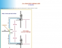
 This project is about a cheap way of building a colinear antenna for VHF 145MHz, and having about 10dB more gain than that little 1/4-wave magmount
 -
 Control an ICOM PCR-100 and listen to the audio stream. This web controlled receiver si based in the Netherlands by PA3ANG and offer 10kHz - 1300MHz in AM, FM, FMW
 -

-
 Reports a 404 error, indicating the requested online receiver resource is unavailable. The page explains that QSL.net hosts over 30,000 websites, each maintained by different individuals, and suggests contacting the website owner directly or performing an internet search to locate the content. It clarifies that QSL.net cannot assist in finding specific missing pages or files. The page also notes that QSL.net provides email and web services free of charge to amateur radio operators and organizations. It encourages donations to support these services, providing a link to more information on how to contribute. The content emphasizes the need for user support to maintain the platform's operations.
 -
 Java script antenna calculators for ground planes, half wave verticals, quad antenna, 5/8th wave vertical antenna, dipole and inverted vee antennas
 -
-
 At LCWO you can learn Morse telegraphy (CW) online in your browser. You don't need to install a program on your computer, and you always have your personal settings available, from any computer on the globe with an internet connection. You can also easily track your progress by means of different statistical functions.
 -
 The total length of the inverted L is 240 feet, which is 7/16th of a wave length long. It has a 92 foot horizontal linear load section 1 foot above ground that terminates into a home-brewed parallel network tuner by KN4LF